Week -2
Week-2
Problem.1: Make a Simulink model of Doorbell using solenoid block with the following details:
In the above arrangement, when the switch is closed the electromagnet receives electrical power from the battery and pulls the metal arm to hit the bell producing sound.
Create a situation where the switch is closed for 2 seconds and then released. Observe the physical movement of the plunger. (Assuming other parameters)
Objective:
To build Simulink model of Doorbell using Solenoid block for
Simulink Block Diagram:
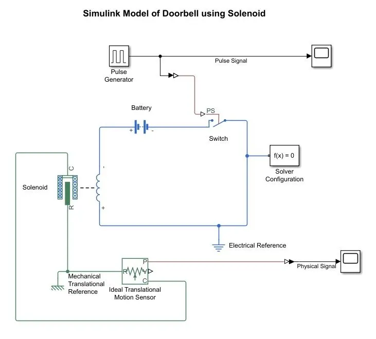
Fig.1.1 Simulink Block Model of Doorbell using Solenoid
Description:
- Open MATLAB/Simulink and select blank model.
- Build the Simulink block diagram using following blocks Pulse Generator, Battery, Switch, Solenoid, Electrical Reference, Mechanical Translational Reference, Translational Motion Sensor, Solver Configuration and scope in accordance to the model of equivalent Doorbell.
- Set the pulse generator with some assumed values like magnitude=1, time period =4sec, % of Pulse width= 50 as mentioned after 2 sec switch has to be released, stop time to 20 Sec and save the file.
- Run the simulation and observe the pulse and physical signal using scope.
Simulated Results:
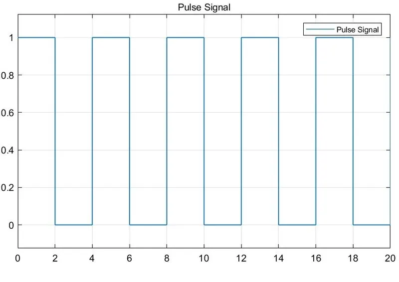
Fig.1.2 Pulse Signal
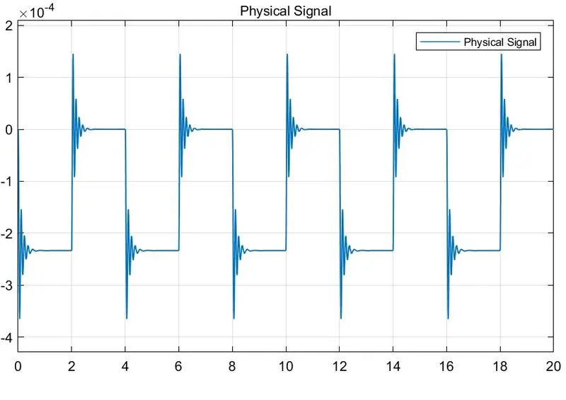
Fig.1.3 Physical Signal
Conclusion:
Hence the Simulink Model of Doorbell using Solenoid block is modelled for a with delay of pulse to the switch and corresponding physical signal is observed.
Problem.2: Use a thermistor to sense the temperature of a heater & turn on or turn off the fan as per the below conditions:
Temperature source: 20 °C from 0 to 10 seconds, 27 °C from 10 to 30 seconds, 23 °C from 30 to 50 seconds
Fan conditions: ON if the temperature above 25 °C, OFF otherwise
Objective:
To develop a Simulink Model to use Thermistor to sense the temperature of a heater & turn on or turn off the fan.
Simulink Block Diagram:
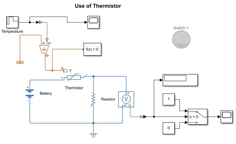
Fig.2.1 Block Diagram to Use Thermistor to control output
Description:
- Open MATLAB/Simulink and select blank model.
- Build the Simulink block diagram using following blocks: Battery, Thermistor, Resistor, Voltage Sensor, Switch, Repeating Sequence Stair, Simulink-PS converter, Controlled Thermal Source, Thermal Reference, Solver Configuration, PS-Simulink Converter, Constant, Scope and Display.
- Covert the given temperatures in Degrees to Kelvin and make in the repeating sequence with sampling time as 10sec. Given for Temperature source: 20°C from 0 to 10 seconds, 27°C from 10 to 30 seconds, 23 °C from 30 to 50 seconds ie., 293K,300K and 296K.
- Run the simulink model considering all other with assumed values for a stop time of 50sec.
- For control of turn on at temperature above 25°C and turn off at temperature below 25°C considering a Threshold value in the switch controlled from a voltage sensor.
Simulated Results:
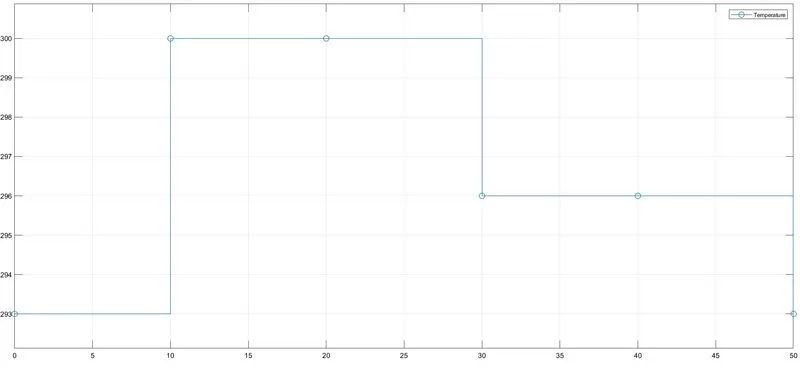
Fig.2.2 Temperature Set Values
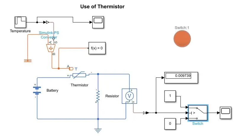
Fig.2.3 Turn-OFF
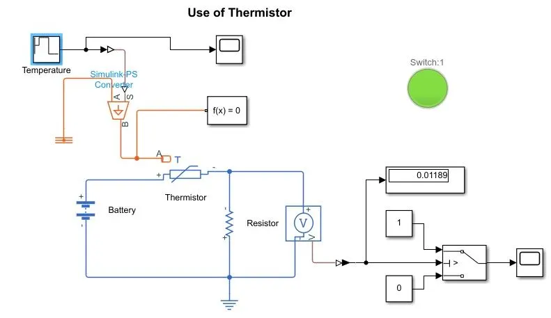
Fig.2.4 Turn ON
Conclusion:
Hence the control turn ON/OFF of a fan can be done using a Thermistor at different values of temperature conditions.
Matlab Simulink Models for Week-2: https://drive.google.com/drive/folders/14QWlOLhUycXrsrNXyZkNyfYSGHAQyHss?usp=sharing