Week -2
Make a Simulink model of Doorbell using solenoid block
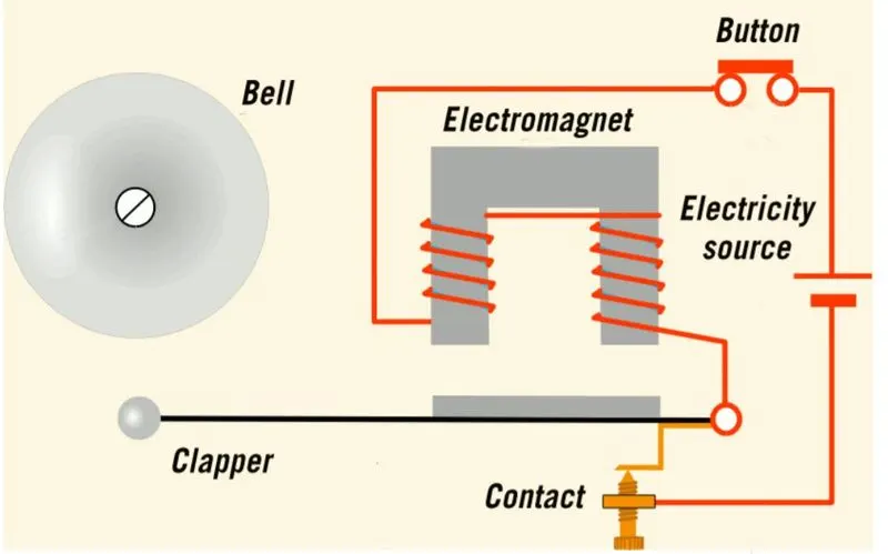
Doorbell: When We Press The Doorbell,This Will Complete a Circuit That Allows Electricity To Flow Through The Doorbell’s Internal Electromagnet. The Magnetic Field Generated By The Electromagnet Is Then Used To Power a Mechanism That Creates The Doorbell Sound. Doorbell Are Low-Voltage Devices.
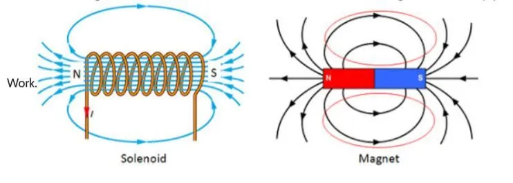
Solenoid:-A Solenoid Is a Device Comprised Of a Coil Of Wire, The Housing And a Moveable Plunger (Armature). When An Electrical Current Is Introduced, a Magnetic Field Forms Around The Coil Which Draws The Plunger In. More Simply, a Solenoid Converts Electrical Energy Into Mechanical
Procedure:-
When The Switch Is Closed The Signal From The Signal Builder Is Transfer To The Circuit By The Simulink-Ps Convertor.
The Battery Which Supply Electric Current To The Circuit And The Solenoid Start Behaving Like An Electromagnet.
And The Behaviour Of Electromagnet Is Sense By The Ideal Translational Rotational Sensor & Its Further Transfer The Signal To The Scope Which Recorded The Behaviour Of Circuit In The Form Of Plot
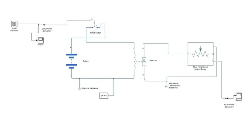
Blocks Which Is Used In Doorbell Circuit
Signal Builder:-Create And Generate Interchangeable Groups Of Signals Whose Waveforms Are Piecewise Linear.
Simulink-Ps Converter:-ConvertSimulink Input Signal Into Physical Signal.
Switch:-Switch Controlled By External Physical Signal.
Solver Configration:-Physical Networks Environment And Solver Configuration.
Electrical Reference:-Connection To Electrical Ground.
Solenoid:-Electrical Characteristics And Generated Force Of Solenoid.
Mechanical Translational Reference:-Reference Connection For Mechanical TranslationalPorts
Ideal Translational Motion Sensor:-Motion Sensor In Mechanical Translational Systems.
Ps-Simulink Converter:-Convert Physical Signal IntoSimulink Output Signal.
Scope:-Display Signals Generated During Simulation.
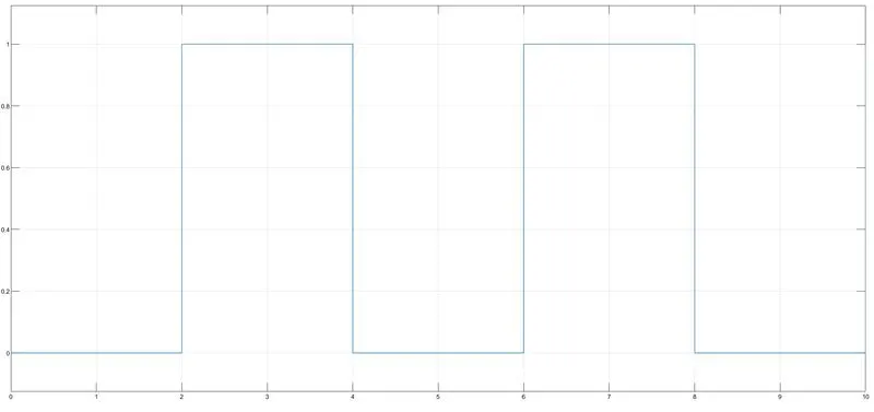
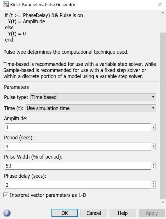
Pulse Generator:
X-axis Time,Y-axis Magnitude
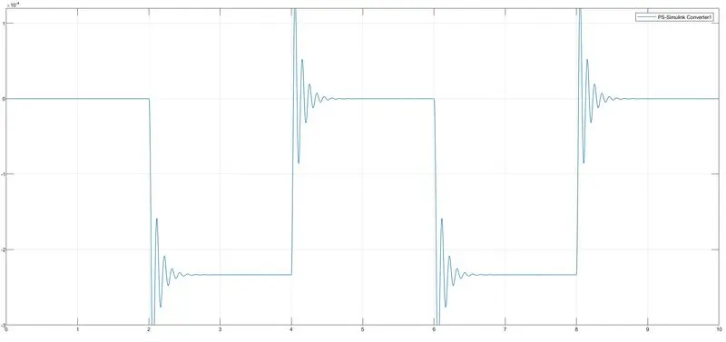
Result:
The Switch Is Closed For 2 Second And Then Released. We Will Record The Value With The Help Of Scope Block.But There Is Fluctuation Is The Signal
X-axis Time,Y-axis Magnitude
Use a thermistor to sense the temperature of a heater & turn on or turn off the fan as per the below conditions:
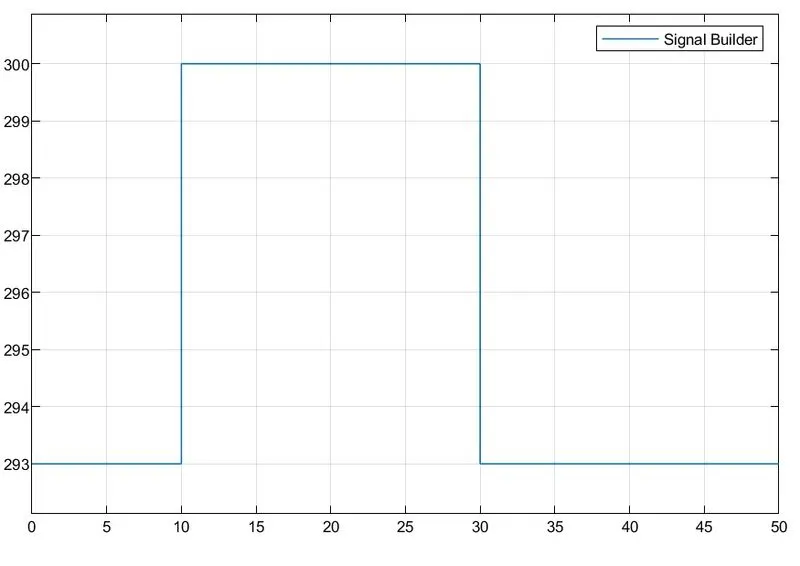
Temperature source: 20 °C from 0 to 10 seconds,
27 °C from 10 to 30 seconds,
23 °C from 30 to 50 seconds
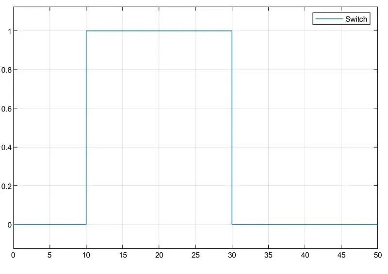
Fan conditions: ON if the temperature above 25 °C, OFF otherwise
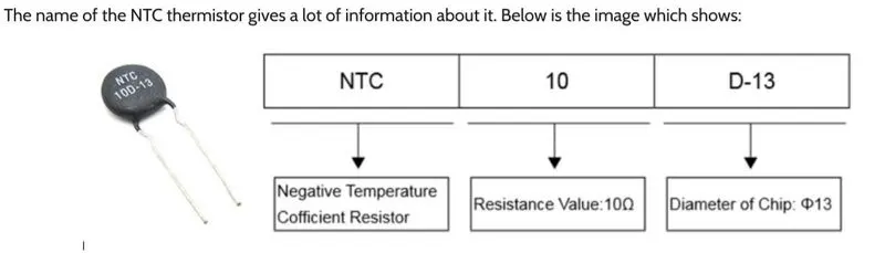
Thermistor:-
A thermistor is a semiconductor that has a resistance capacity more than a conducting material and less than insulating
material. Its electrical resistance varies with the change in the temperature or thermally sensitive resistor. There are mainly two types of thermistors, namely the Negative Temperature Coefficient (NTC) and the Positive Temperature Coefficient (PTC).
Thermistor’s relation with temperature also depends on the material in which it is made. A negative temperature coefficient
(NTC) the thermistor will decrease its resistance value when temperature increases whereas a Positive temperature coefficient will
increase its resistance when temperature increases. The electronic symbol of the thermistor is given below
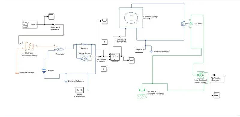
blocks required for the problem. For this challenge, the requirements are listed below
Signal Builder - to generate the signal according to the input condition given
PS-Simulink converter: Converts Simulink signals to the respective physical signal.
Controlled temperature source: (CTS) Provide a temperature physical output based on the condition given to port S.
Thermal reference: Thermal reference block provides the required initial conditions to the connected thermal block for the
solver.
Thermistor: Thermistor block which shows us the NTC thermistor relation between temperature and resistance.
Battery: Battery is a storage device that provides the required voltage based on the parameter given. We can use DC
voltage source blocks too.
Resistor: Resistor which provides the opposing nature of current in a circuit.
Voltage sensor: This is used to measure the voltage or potential difference across any electrical component and it should
connect in parallel only.
Electrical Reference: These domain-specific electrical reference blocks will provide the required initial conditions to the connected thermal block for the solver.
Solver Configuration: The Solver Configuration block specifies the solver parameters that your model needs before you
can begin simulation and this is mandatory for all simscape designs.
PS-Simulink Converter: Converts physical signals to the respective Simulink signal.
Constant: Provides a constant output value
Switch: This block is used from the library Simulink / Signal Routing where it has three inputs namely Port1, Port2, and
Port3. Port2 is a control input where the signal given to port2 is satisfied with the condition and threshold of the switch block then it passes Port1 as output and if it is not satisfied then it will pass Port3 as output.
Scope: This is an output block that shows the signal with respective times in an X-axis.
Condition: Input -
0 to 10-sec temp is 20 °C Output - Fan should be ON only > 25 °C
10 to 30-sec temp is 27 °C else OFF
30 to 50-sec temp is 23 °C
X-axis Time,Y-axis Temperature
Output at the switch:
X-axis Time,Y-axis Magnitude
Output at the end of the DC Motor
X-axis Time,Y-axis Magnitude
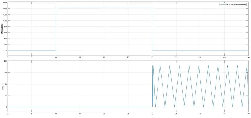
From 0-10sec the motor is off and then from 10-30sec it's later from 30-50 secs it's Off the entire operation of the dc motor is controlled by the thermistor wherein the input signals are given by the signal builder.