Week -2
#Part1
Aim:
Simulink model of doorbell using solenoid block.
Condition:
Switch is closed for 2seconds and then released.
Solenoid:
- Solenoids are a type of electric motor. They are commonly used in cars as heavy-duty relays. The technical definition of a solenoid is a device or motor that can produce back and forth, or liner, motion when a force is applied. Solenoids will respond to hydraulic, pneumatic or electrical force.
- A solenoid is created by winding copper wire over a cylindrical casing, when electricity is passed through the coil the solenoid acts like a magnet, in this project, we have used a solenoid valve to demonstrate the working of the doorbell.
Simulink Model:
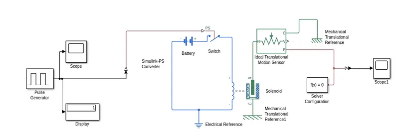
Block used in model:
- Pulse Generator
- Display
- Scope
- Simulink PS converter
- Switch
- Battery
- Solenoid
- Ideal translational motion sensor
- Mechanical translation reference
- Electrical reference
- Slover configuration
- PS Simulink converter
Pulse generator:
The pulse generator block generates square wave pulse at regular intervals and waveform parameters amplitude pulse width, period and phase delay determine the shape of the output waveform.
Scope:
display signals generated during simulation.
Simulink PS Convertor:
Its convert the unitless Simulink input signal to a physical signal.
Switch:
Switch controlled by an external physical signal.
Battery:
The battery block represents a simple battery model.
Solenoid:
Model electrical characteristics and generated force of solenoid.
Ideal translational motion sensor:
The ideal translational motion sensor block represents a device that converts an across variable measured between two mechanical translational nodes into a control signal proportional to velocity or position. You can specify the initial position(offset) as a block parameter. The sensor is ideal since it does not account for inertia, friction, delays energy consumption and so on.
Mechanical translational reference:
The mechanical translational reference block represents a reference point, or frame for all mechanical translational ports, all translational ports that are rigidly clamped to the frame(ground) must be connected to a mechanical translational reference block.
Electrical Reference:
The electrical reference block represents an electrical ground. Electrical conserving parts of all the blocks that are directly connected to the ground must be connected to an electrical reference block. A model with electrical elements must contain at least one electrical reference block
Solver configuration:
The solver configuration block specifies the solver parameter that your model needs before you can begin the simulation.
PS Simulink converter:
Convert physical signal into Simulink output signal.
Model Explanation:
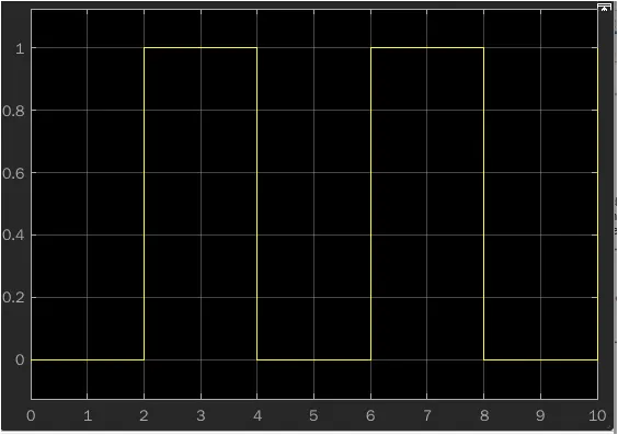
A pulse generate is given as input with following specifications. The condition was that the bell is engaged for 2 s and then released. Same was implemented by giving period as 4 s and pulse width as 50% of 4s i.e 2s. phase delay was given as 2s, so the simulation starts from the unengaged condition of switch.
The signal from the pulse generator was converted using Simulink PS convertor and is given as the input to the switch. A solenoid is introduced, and battery is connected to it. The voltage of the battery connected was made as the same that of the rated voltage of the solenoid. The switch is also connected to the same circuit. The position of solenoid plunger is measured using an ideal translational motion sensor connected to the circuit. Initial position was set 5mm in translational motion sensor. Both mechanical and electrical references were connected to the respective circuits. The output from the ideal translational motion sensor is converted using a PS converter and is given to the scope to display the results. A scope was also connected to the input to visualize its behaviour. The spring constant and damping parameters of the solenoid block was altered to obtain designed graph.
Output:
Observation:
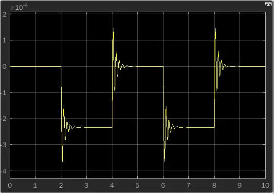
As we can see from the above plaot, the motion is getting generated for 2s and stayeing idle for 2s andthis loop is getting repeated throughout the simulation time.
We can interprete that this motion can be transferred to the arm which is connected to a doorbell, thereby producing sound whenever there is motion in the solenoid block.
Conclusion:
The creatioon of doorvell is done using simulink and observed the output results generated from the motion sensors, the result is satisfactory.
#Part2
Aim:
Use a thermistor to sense the temperature of a heater & turn on or turn off the fan.
Conditions:
Temperature source: 20 °C from 0 to 10 seconds, 27 °C from 10 to 30 seconds, 23 °C from 30 to 50 seconds
Fan conditions: ON if the temperature above 25 °C, OFF otherwise
Blocks used in model:
- Repeating sequence stair
- Simulink PS Convertor
- Controlled temperature source
- Thermal reference
- Solver configuration
- Thermistor
- Resistor
- Voltage sensor
- Battery
- Switch
- Scope
- Display
- Constant
- PS-Simulink convertor
- Electrical Reference
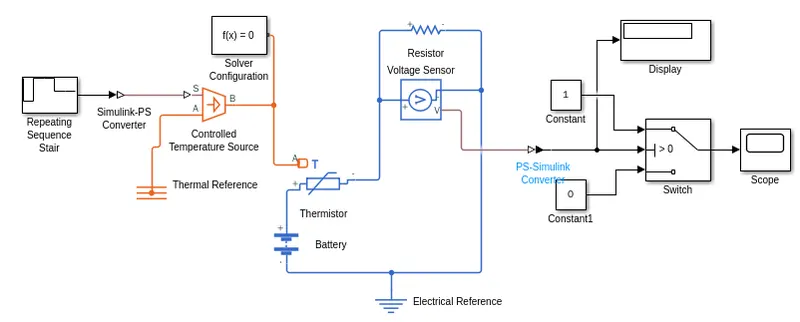
Controlled temperature source:
The controlled temperature source block represents an ideal source of thermal energy that is powerful enough to maintain specified temperature difference across the source regardless of the heat flow consumed by the system.
Connection: A and B are thermal conserving ports corresponding to the source inlet and outlet. Respectively port is a physical signal port through which the control signal that drives the source is applied.
Thermistor:
The thermistor is a type of resistor whose resistance is dependent on temperature more so than in standard resistor.
The thermistor Block represents an NTC thermistor using the B-parameter equation.
NTC-Negative temperature Co-efficient
Resistor:
The Resistor block models a liner resistor, described with the following equation:
Where V=IR
V=Voltage, I= Current, R=Resistance
Voltage sensor:
The voltage sensor block represents an ideal voltage sensor that is a device that converts voltage measure between two points of an electrical circuit
Electrical reference:
The electrical reference block represents an electrical ground. Electrical conserving ports of all the blocks that are directly connected to ground must be connected to an electrical refence block. A model with electrical elements must contain at least.
Model Creation:
- We give temperture inputs at eveery 10s for 50s. We give temperture in kelvin. Tempertures are 293, 300, 300, 296, 296 for every 10s.
- Add signal repeating sequence stair block for input tempertures. Give tempertures as above and sample time as 10s. here sample time means each value of temperture at a certain time period.
- Give scope for repeating sequence stair block for knowing the input plot of it.
- Add controlled temperture source block for maintaining temperture. Join the stair block to controlled source with the help of simulink PS converter. Add at the point S
- Add temperture reference block and conect with the point A
- Add themistor block and Join the point A with point B of the source block.
- Add Battery block for source to pass the current in the circuit.
- Add voltage sensor block and resistor block and connect with the themistor. Add an electric reference block.
- Connect all connections as shown in the circuit
- Since we need to operate in ON and OFF conditions. We add a switch block with inputs. Inputs are given as 0 and 1 with two constant blocks.
- Connect the point V of votlage sensor to the switch. The switch operates in the valuves between 0 and 1. Its joined with the help of a converter block.
- We use display block to know the threshold value and connect with switch
- Scope block to know the output from the switch.
Output:
From the final output in the scope on the axis is shown that at the temperature above the 25degree Celsius the fan switch is in ON position and the remaining is in OFF position.
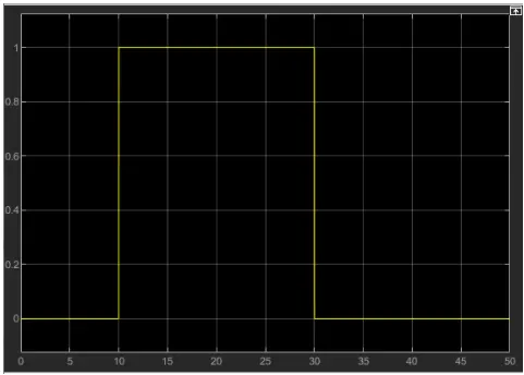
Here X-axis represents time range and the Y-axis represents the temperature range.
Conclusion:
Therefore in the first 2s bell has rung and then stopped using solenoid and also in the second model when temperature is reached above 25 degree Celsius fan is in ON position.