Week -2
1.Answer:
Aim: To observe the physical movement of the plunger
Components used: The following blocks are used in this simulation.
- Battery
- Switch
- Solenoid
- Ideal Translational motion sensor
- Electrical and Mechanical Reference
- PS-Simulink converter and
- Scope
Simulation Circuit: The below figure is the simulation circuit of a door-bell arraignment to observe the physical movement of the plunger.
Description of the circuit:
The simulation circuit of a door-bell arraignment to observe the physical movement of the plunger is shown in fig.1.
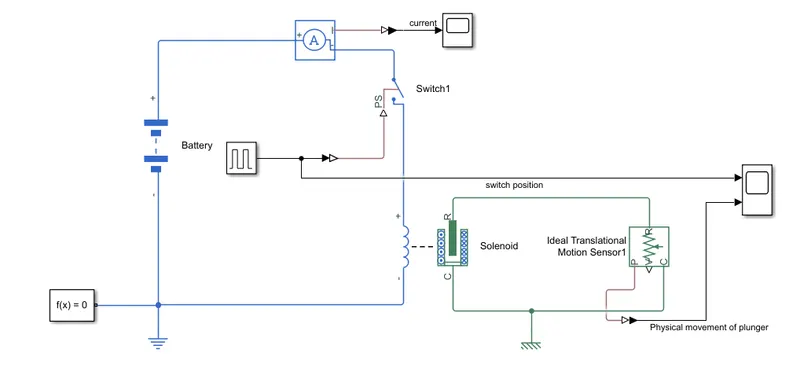
Fig.1. Simulation circuit of a door-bell arraignment
The battery, switch and the solenoid are connected in series. In order to turn-on and off the switch a pulse generator is connected to switch. The amplitude of the pulse is ‘1’, period of the pulse is ‘4’ (sec), pulse width is ‘50%’ and phase delay is ‘0’. With this signal, the switch is on for a period of ‘2’ sec and off for ‘2’ secs as shown in fig.2.
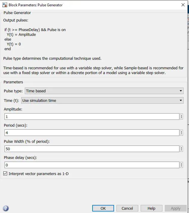
Fig.2. Pulse Generator block parameters
When the switch is in on state, the electromechanical force pulls the plunger an when the switch is in off state it will releases the plunger. The switch position and the physical movement of the plunger is shown in fig.3.
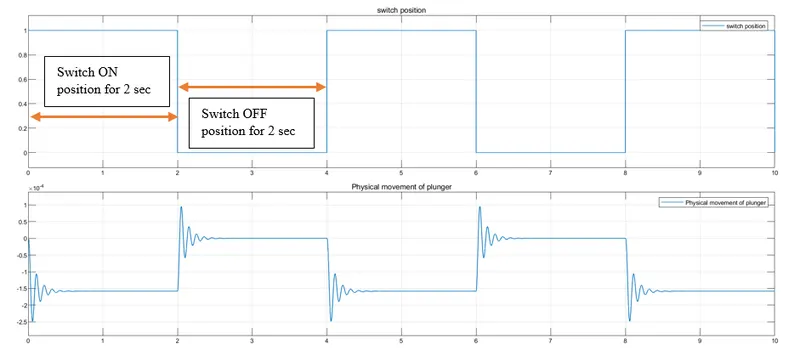
Fig.3. Simulation results of the switch position and the physical movement of the plunger
2.Answer:
Aim: To Control a fan using a thermistor
Components used: The following blocks are used in this simulation.
- Battery
- Thermistor
- Signal builder
- Controlled Temperature Source
- Switch
- Thermal and Electrical Reference
- PS-Simulink converter and
- Scope
Simulation Circuit: The below figure is the simulation circuit to control a fan using a thermistor.
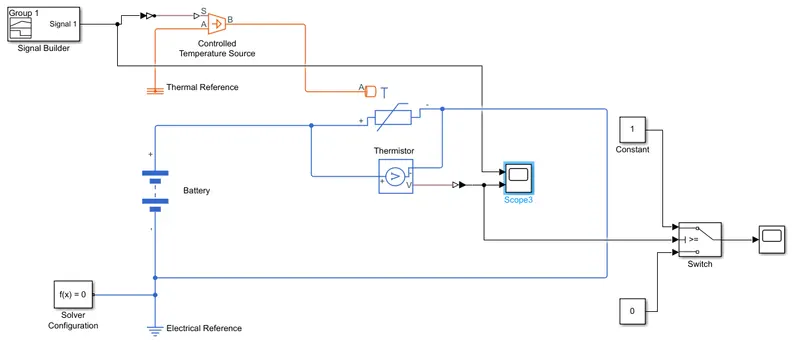
Fig.4. simulation circuit to control a fan using a thermistor
Description of the circuit:
The given temperatures are
20 °C from 0 to 10 seconds
27 °C from 10 to 30 seconds
23 °C from 30 to 50 seconds
The above temperatures are converted into kelvin and the new temperatures are
293.15 From 0 to 10 seconds
300.15 From 10 to 30 seconds
296.15 From 30 to 50 seconds.
The new temperatures are generated by using a signal builder. Double click on signal builder. Then go to signals > new > custom as shown below.
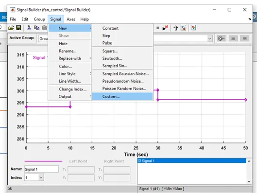
Fig.5. Generation of a custom signal by using a Signal builder
After clicking of custom a new window will open as shown below.
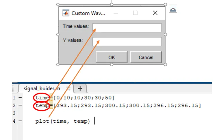
Fig.6. Generation of a custom signal by using a Signal builder with matlab script
For entering the values in time values and Y values, I use a Matlab m.code as shown above.
After running the code, enter the same variables name in time values and Y values. Then click on ok. With that you will get a custom signal as shown below in fig.7.
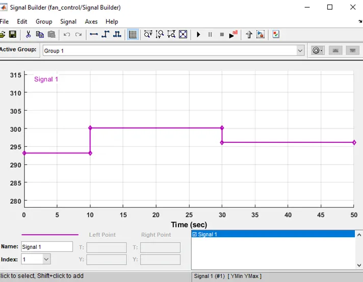
Fig.7. Obtained custom signal as per requirement
Once the signal is generated, the same is connected to the controlled temperature source via a ps-simulink converter. The B port of controlled temperature source is connected to thermistor. The positive terminal of the thermistor is connected to positive terminal of the battery.
The simulation waveforms of the signal builder and the temperature across the thermistor as shown in fig.8.
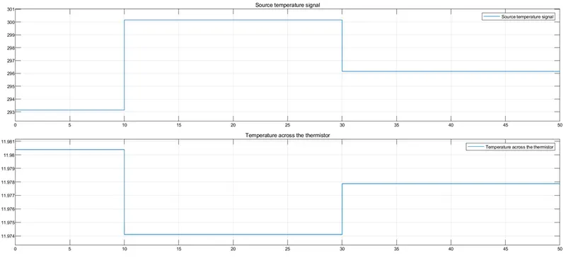
Fig.8. simulation waveforms of the signal builder and the temperature across the thermistor
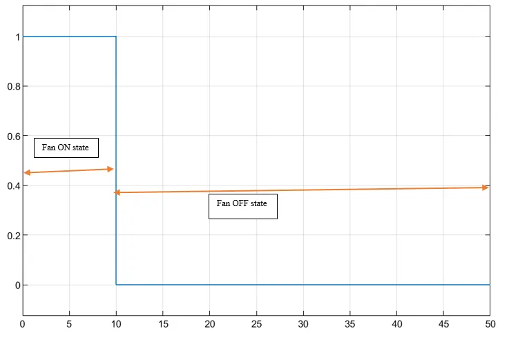
The temperature across the thermistor is given to switch which is having a threshold value of 11.98(user defined). When the temperature across the thermistor value is greater than or equal to threshold, then the output value is equal to 1, else 0. So when the output value is 1 the fan is in on state and if the output value is 0 the fan is in off state as shown in fig.9.