Week -2
Solution 1: Simulink model of Doorbell using solenoid block
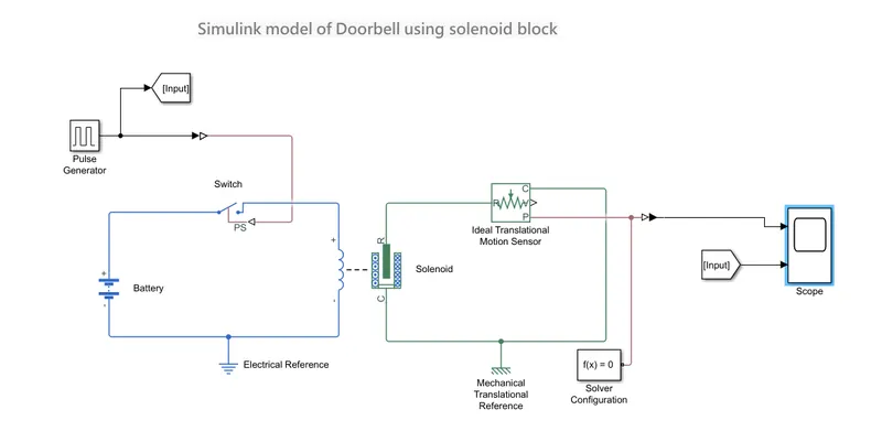
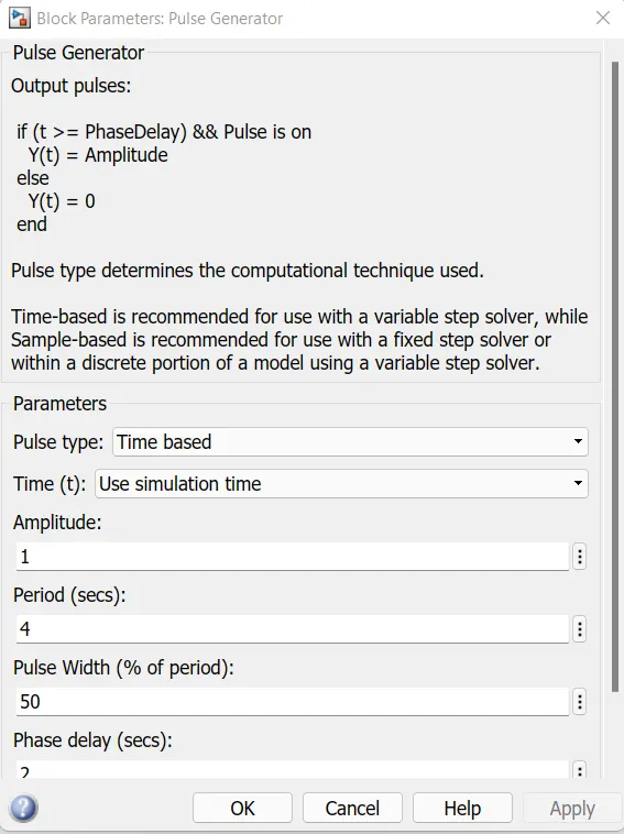
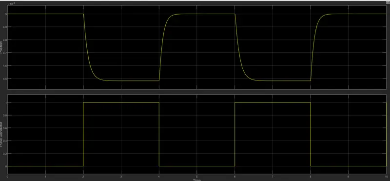
Step 1: A pulse generator input signal given to the circuit with condition 2 sec delay as mentioned problem. Period was 4 sec, pulse width 50% and amplitude was 1.
Step 2: Pulse generator output was connected to electrical switch via Simulink PS converter and the input is observed by connecting scope.
Step 3: Then the solver configuration block is connected to the switch.
Step 4: Battery block was defined for Voltage source.
Step 5: The battery was connected to an electrical switch and the switch is connected to the solenoid to complete the circuit.
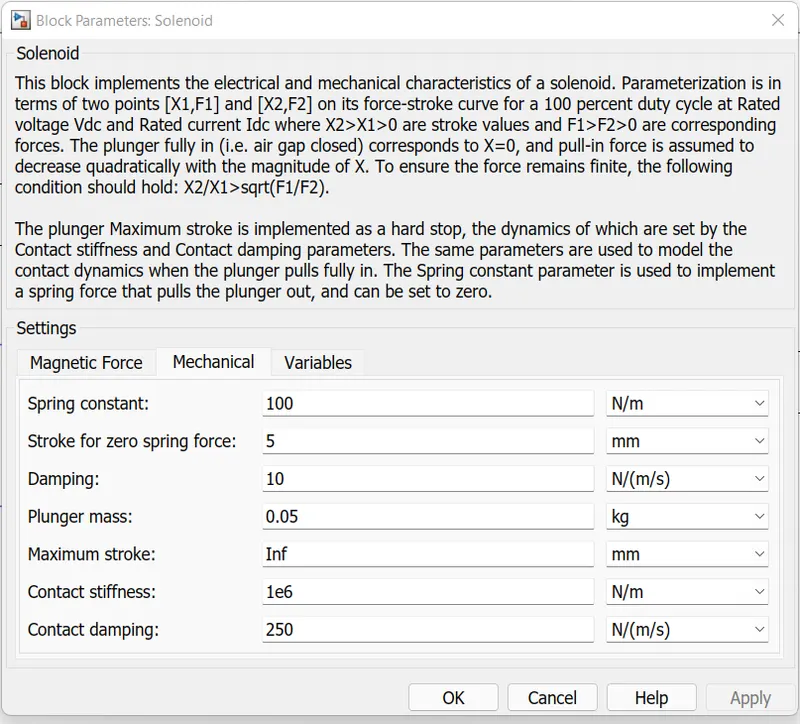
Step 6: Then we give the block for solenoid and connect it to an Ideal translational motion sensor to measure the translatio motion of the solenoid,
Step 7: The translation motion of the bell is observed by connecting it to a scope with the help for PS Simulink converter.
Step 8: Electrical reference and Mechanical translation reference connected as earthing.
Output Graph :
Solution 2: Use a thermistor to sense the temperature of a heater & turn on or turn off the fan.
Conditions:
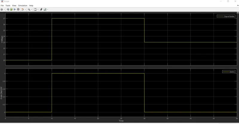
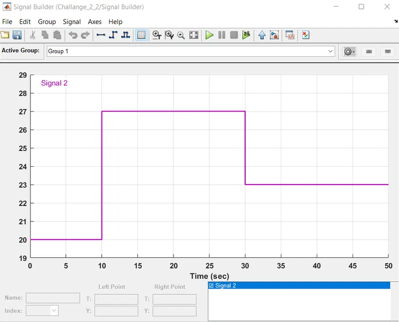
- 0-10 sec temperature 20°C
- 10-30 secs temperature 27°C
- 30-50 secs temperature 23°C
- Fan conditions: ON if the temperature above 25 °C, OFF otherwise
Step 1: We can see these details in graph basis in signal builder block where the input is connected with these signals.
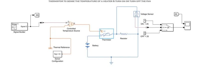
Step 2: We have to use simulink to PS Converter to read the system. here we have to change the parameter handling to first order system.
Step 3: Controlled Temperature Source Has A/B/S Ports. The signal was sent to S port. A port connected with Thermal reference and solved configuration. B port was connected to thermistor
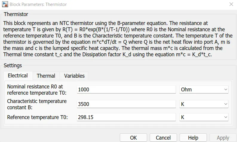
Step 4: Thermistor block represents an NTC thermistor using the B-parameter equation. The resistance at temperature T is given by R(T) = R0*exp(B*(1/T-1/T0)) where R0 is the Nominal resistance at the reference temperature T0, and B is the Characteristic temperature constant.
Step 5: Battery positive terminal connected with thermistor positive terminal and negative to thermistor negative thru resistor R1.
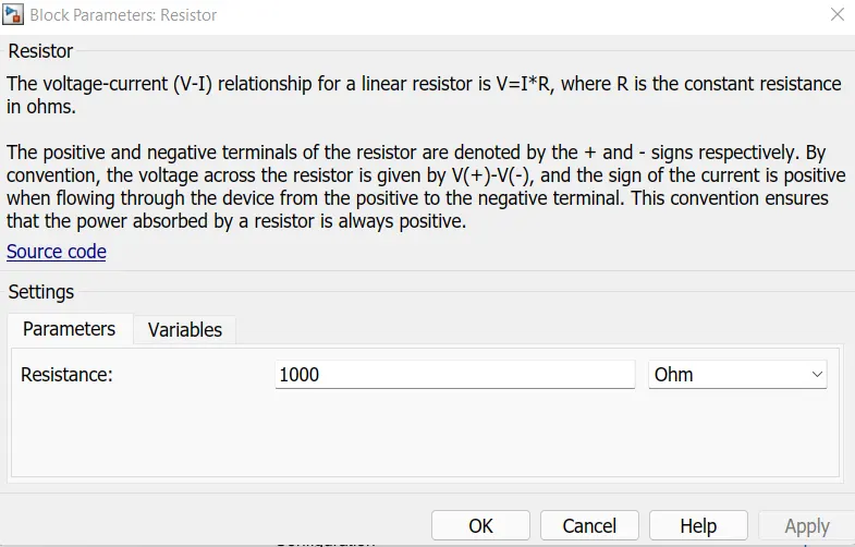
Step 6 : Connect voltage sensor parallel to measure the different voltage level based on change in resistance value. here we have to use voltage divider rule to get voltage values.
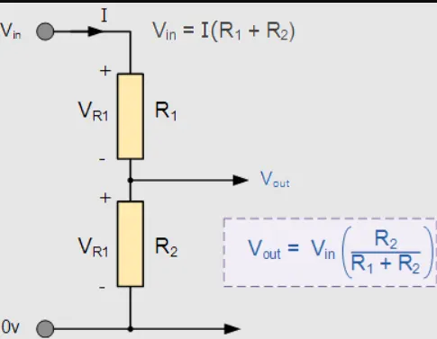
Step 7 : When the temperature increases voltage also incresed and resistance will be decresed. use different resistance values to change the voltage ranges.
Step 8 : Voltage output sensor was connected to Switch via PS to simulink converter to statisfy the FAN Condition as above.
Step 9 : Here we have to create 2 constant values 1 and 0 to connect inputs to switch as per conditions given. change the Threshold value to 25 to statisfy the FAN Condition.
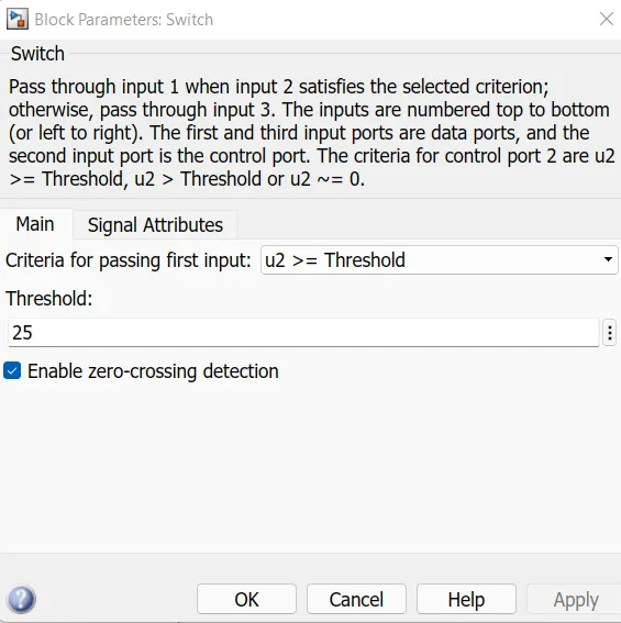
Step 10 : Once the output condition was statisfies then signal pass to either port 1 or port 2 to Scope to measure the final output.
Output Graph: