Week -2
Answer 1: Below is a Simulink for Door Bell using Solenoid Block.
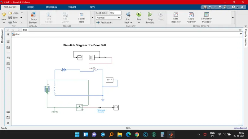
Explanation for the above Sumulink Model of the Door Bell :-
The Pulse Generator is used to create sqaure wave pulses at regular intervals. The block wave form parameters Amplitude, Pulse width, Period & Phase Delay determine the shape of the output form.
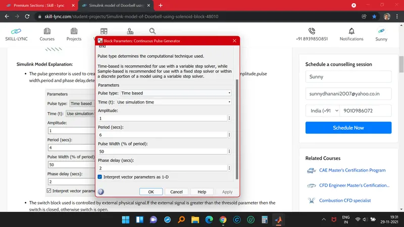
- The Switch Block used is controlled by external physical signal.
- If the external physical signal is grater than the threshold parameter, then the switch is closed otherwise its open.
- The positve terminal of the switch is connected to Switch and the negative to Electrical Reference block.
- The Solenoid Block is connected with switch & battery block, then a circuit is completed.
- The port c is connected with mechanical reference.
- The Ideal Translational Sensor is connected with Solenoid Block to observe the movement of the plunger.
- Scope is connected with the ideal translational sensor to the output.
- PS- Simulink Convertor is used to convert physical signal to simulink signal.
- Solver Configuration: Each Physical network represented by a connected simscape blocks requires solver setting information for simulation.
Google Drive Download:
https://drive.google.com/file/d/10beFr80BIJSNc5RAhgQA4EwXrKxhn0AL/view?usp=sharing
_______________________________________________________________________________
Answer 2. Using a thermistor to sense the temperature of a heater & turn on or turn off the fan as per the below conditions:
Temperature source: 20 °C from 0 to 10 seconds, 27 °C from 10 to 30 seconds, 23 °C from 30 to 50 seconds
Fan conditions: ON if the temperature above 25 °C, OFF otherwise
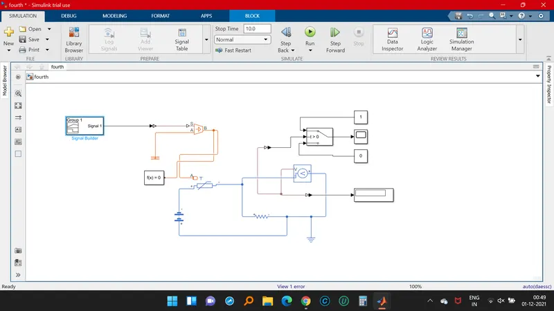
- Signal Builder Block is used to give inputs.
- Controlled Temperature Source respresents an ideal source of thermal energy, that can maintain a controlled temperature difference regardless of heat flow rate.
- Thermistor is a type of resistor whose resistance is based upon temperature.
- A linear resistor is used to control the amount of current from the battery.
- The voltage sensor is used to control the voltage measured between two points into a physical signal.
- Voltage source represents either Ac or DC.
- Electrical reference block is given.
- Solver configuration is provided for each physical network respresented by a connected simscape blocks for solver configuration.
Google Drive:
https://drive.google.com/file/d/17fXs8lJTExk8_GJnlVBxuTmCq3m9xWdu/view?usp=sharing