Week -2
1.
Aim: To create a simulink model and observe the physical movement of the plunger which is driven by a metal arm by a battery.
Blocks used:
1. Pulse generator
2. Simulink to PS converter
3. Battery
4. Switch
5. Solenoid
6. Translational motion sensor
7. Solver configuration
8. Electrical reference
9. Mechanical translational reference
10. PS to Simulink converter
11. Scope
Simulink model:
Pulse generator setting
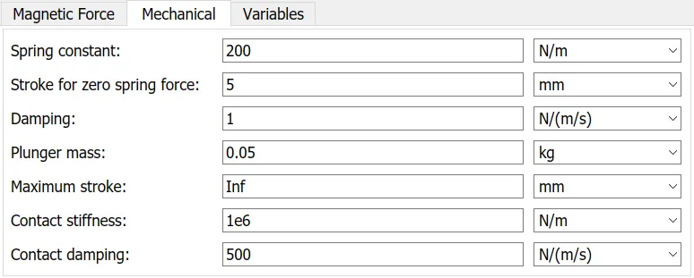
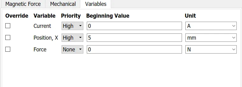
Solenoid settings
Procedure:
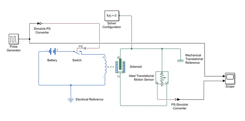
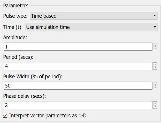
1. The pulse generator generates pulses in square wave for every 2 seconds. As the switch that need to be connected is a physical system, Simulink to PS converter is connected between pulse generator and switch. The pulse generator is further connected to the scope in order to view the generated pulse and its corresponding response
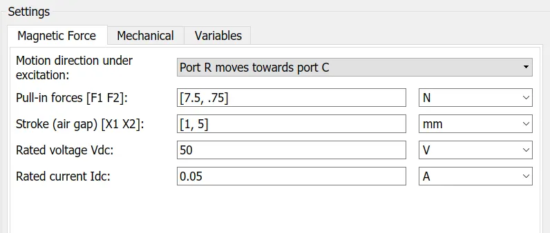
2. The switch is connected to a battery which controls the solenoid to actuate. So whenever there's a rising pulse, the switch closes and solenoid gets actuated by the battery forming a closed circuit.
3. The plunger movement is identified and captured by connection a translational motion sensor to the solenoid and viewed in the scope.
4. As the simscape blocks are connected here, solver configuration is connected in order to acquire solver setting configuration for physical systems.
Result:
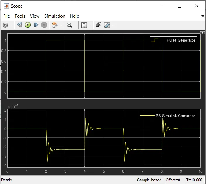
From the above graph, it is infered that for every rising pulse of the pulse generator the switch connected to it has been closed and formed a closed circuit to drive the solenoid and that is evident from the response of plunger in the second graph.
2.
Aim: To create a simulink model in which a thermistor is used to sense the temperature of a heater & turn on or turn off the fan accordingly
Blocks used:
1. Signal builder
2. Controlled temperature source
3. Thermistor
4. Resistor
5. Voltage sensor
6. Battery
7. Switch
8. Solver configuration
9. Scope
10. PS to simulink converter
11. Simulink to PS converter
Simulink model:
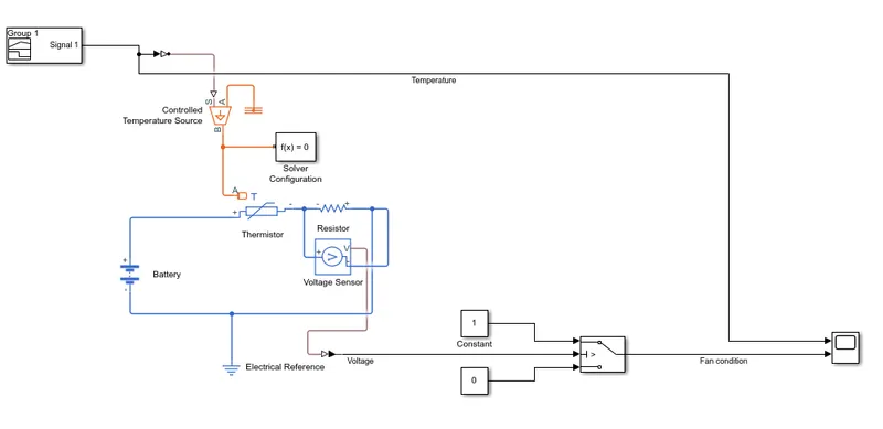
Resistance value: 100 Ohms
Procedure:
1. Set the limits of signal builder as shown below
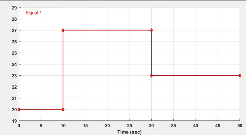
2. Feed the signal as an input to the controlled temperature source via Simulink to PS converter
3. Next, the thermistor is connected to the battery and a resistor.
4. A voltage sensor is connected across the resistor in order to control the output of fan with respect to the temperture fed.
5. The voltage obtained w.r.t the temperature obtained from the signal builder is connected to the switch via PS to simulink converter.
6. To perform the condition of fan switching, switch block is taken where voltage across the resistor is taken as reference. If the reference is greater than the threshold value, fan will be switched ON. If not, fan will remain in off condition.
7. The threshold is found by connecting the voltage and input temperature to the scope
8. After the threshold is found, it is entered in the condition and set to run the simulation
9. Sample time is taken as 10s and the simulation time as 50s
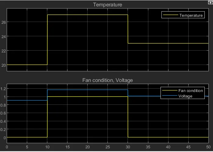
10. When the temperature crosses 25 degC, the fan is switched ON whereas below 25 degC fan remains in OFF condition.
Result:
Hence the fan remains in ON condition from 10 to 30 seconds, whereas from 0-10s and 30-50s fan remains in OFF condition