Week -2
Question:01
Aim:
1.To simulate Door bell using Solenoid with following conditions
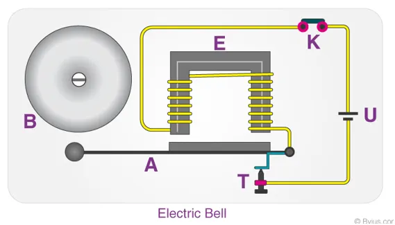
In the arrangement, when the switch is closed the electromagnet receives electrical power from the battery and pulls the metal arm to hit the bell producing sound.
where the switch is closed for 2 seconds and then released.
2.To Observe the physical movement of the plunger.
Body of the content :
Operation of door bell :
- The switch is made on and current flows through the circuit.
- The electromagnet is powered and generates a magnetic field that attracts the iron strip towards it.
- The striker strikes the gong (bell).
- When the striking arm strikes the gong, the contact is broken and current stops flowing through the circuit.
- This causes the electromagnet to lose its magnetic field.
- The connected spring arm returns the striker to its original rest position.
- The contact is restored and current flows through the circuit (provided the main switch is still pressed).
- The process is repeated from the beginning.
-
Simulink model:
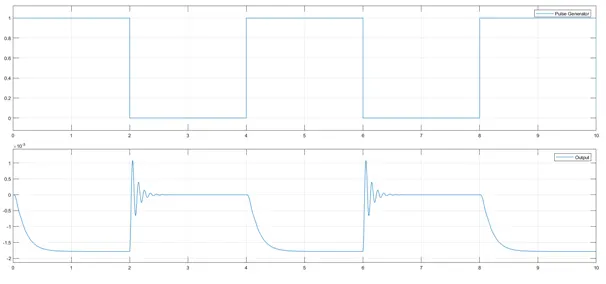
In the above Simulink model the input to the switch is fed by a pulse generator with period of 4 sec and 50% Pulse width .
When the switch is closed the electrical energy from the battery is passed through the solenoid which helps in creating mechanical energy to pull the metal arm
Output: 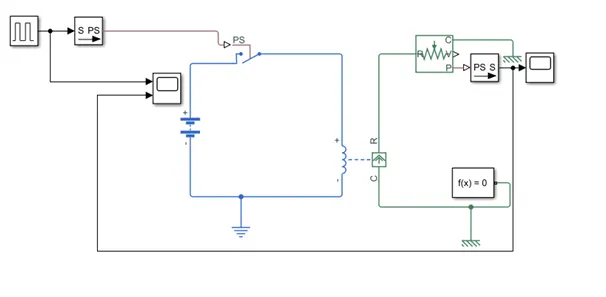
-
Conclusion:
When the bell rings the output is high . It means the circuit is broken and there is no flow of current
When the spring regains it the electrical energy start flowing through the circuit.
Question:2 -
Aim:
To simulate a model by using the following conditions
1. A thermistor to sense the temperature of a heater & turn on or turn off the fan as per below conditions:
Temperature source: 20 °C from 0 to 10 seconds, 27 °C from 10 to 30 seconds, 23 °C from 30 to 50 seconds
Fan conditions: ON if the temperature above 25 °C, OFF otherwise
Body of the content :
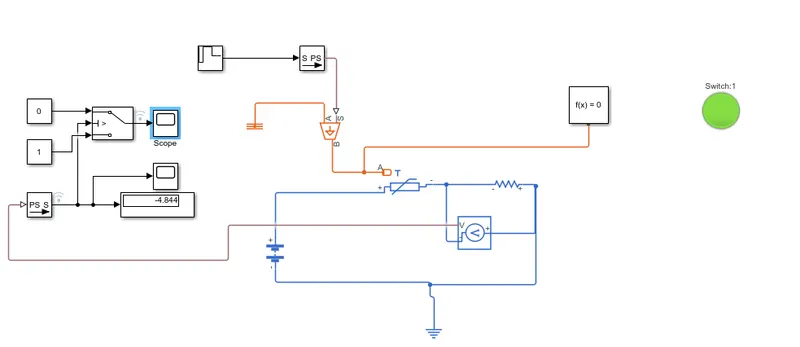
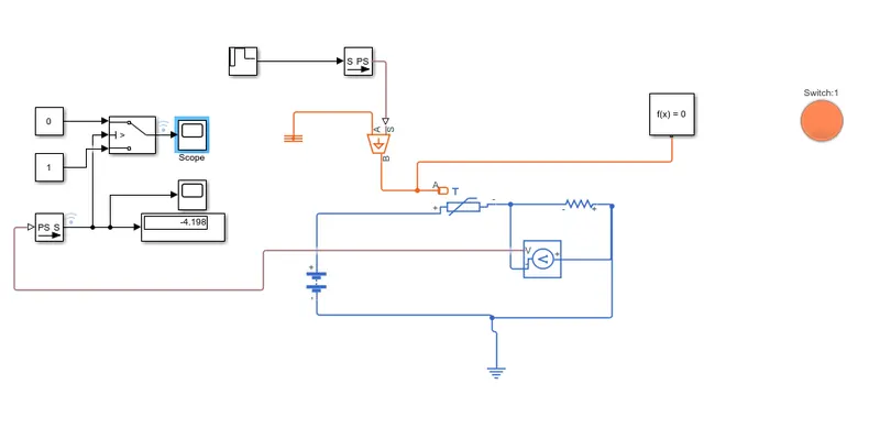
In the below simulink model , A battery is used for voltage source . - The thermistor is connected to the battery and resistor .
- A Voltage sensor is used to measure the temperature of the resistor which is the model of a heater
- The temperature to the thermistor is provided through Repeating sequence stair with a Controlled temperature source
- As mentioned in the aim, the lamp should be on if the temperature is above 25 deg celsius So it is equivalent to 298 k .
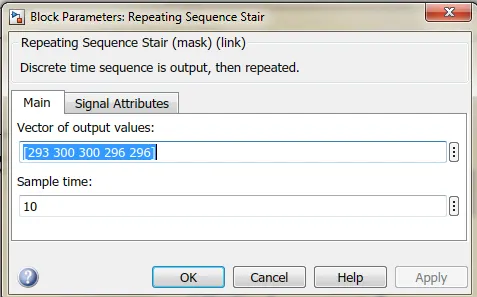
- The input to repeating sequence stair is given as 0 to 10 sec-20+273=293k, 10 to 30 sec -27+273=300k,30 to 50 sec -23+273=296k with sampling time of 10 s .Total time period of Simulation is 50s
- A switch is used as input to the lamp which reads 0 or 1 based on the threshold Voltage input.
- The threshold voltage is given by simulating the model with 298k(25deg) at a specified Voltage and resistance .
- The Lamp is on for temp above 25deg as green colour and off is indicated with red colour .
- Simulink model:
- Repeating sequence stair input:
- When the temperature is above 25 deg(given temp -300k):ON condition
- When the temperature is below 25 deg(given temp -296k):OFF condition
- Switch output for time period =50 s:
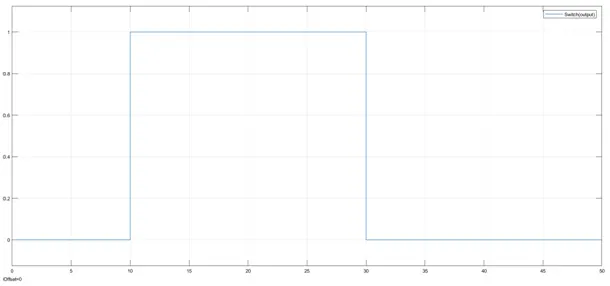
- Conclusion: The lamp and Switch are in "on" condition when the temp is 300k(temp>298k) and off for temp<298k