Week -2
WEEK 2 - CHALLENGE 1:
AIM:
To create the Simulink model of doorbell block for the situation where the switch is closed for 2 seconds and then released to observe the physical movements of the plunger.
SOLENOID:
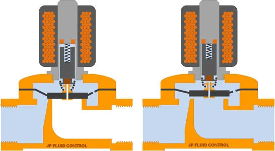
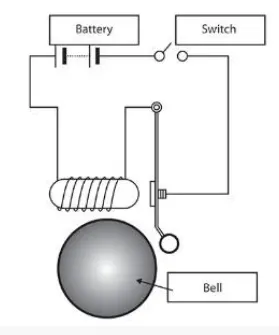
A solenoid is an electromagnetic device consisting of coils and wires, the housing, and the plunger (armature) which is moveable. Whenever the electrical input is given, it forms the magnetic fields which draw the plunger in. So basically it is the conversion of electrical energy into mechanical energy.
BLOCK DIAGRAM OF SIMULINK:
PROCEDURE:
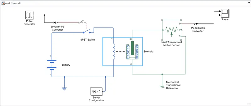
- The pulse generator generates the continuous pulses of a regular given time interval which is given to switch through the Simulink - PS converter.
- One part of the SPST (single pole single through) switch is connected to the battery and the other is connected to the solenoid.
- The other part of the battery is connected to the solenoid with the ground (electrical reference) with solver configuration.
- The solenoid is connected with the ideal transformation motion sensor with mechanical translational reference and the same connection to the scope via PS-Simulink converter to view the output.
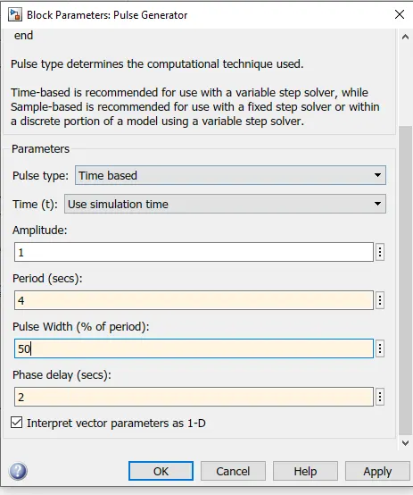
The phase delay given is 2 secs as shown.
OUTPUT:
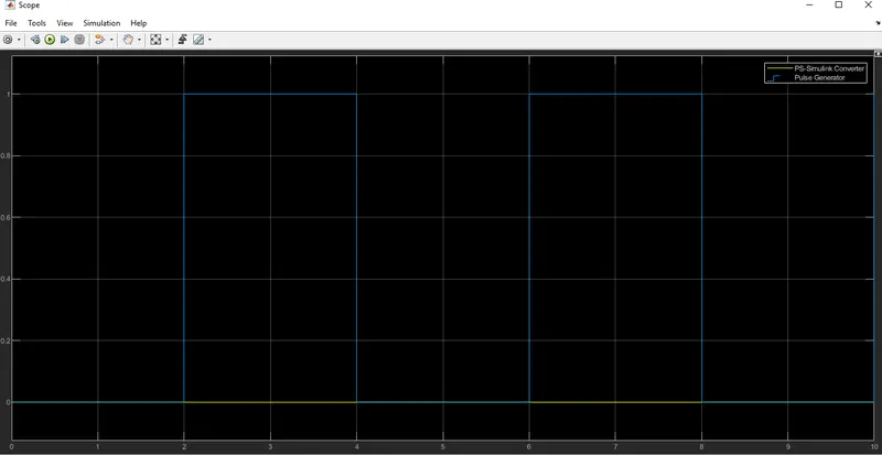
The time delay is given 2 secs to the pulse generator to open and close the switch, When the switch is closed, the solenoid receives the electrical power which moves the plunger and produces the bell ring.
WEEK 2 - CHALLENGE 2:
AIM:
Using a thermistor to sense the temperature of a heater & turn on or turn off the fan when the temperature source is 20 °C from 0 to 10 seconds, 27 °C from 10 to 30 seconds, 23 °C from 30 to 50 seconds assuming fan condition is ON only when the temperature is above 25 °C.
FAN CONTROLLED BY THERMISTOR:
The thermistor is the temperature-controlled device that senses the temperature and changes the resistance values accordingly.
BLOCK DIAGRAM:
 PROCEDURE:
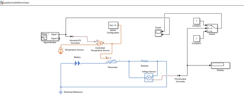
- Signal builder block is used to give the input as per the given requirement given.
- A controlled temperature source represents the ideal source of thermal energy that maintains controlled temperature differences regardless of heat flow rate.
- One part of the controlled temperature source is connected to the thermistor and the thermistor is connected to the resistor.
- The resistor is connected to the voltage sensor which is used to convert the voltage measured between two points into the physical signal.
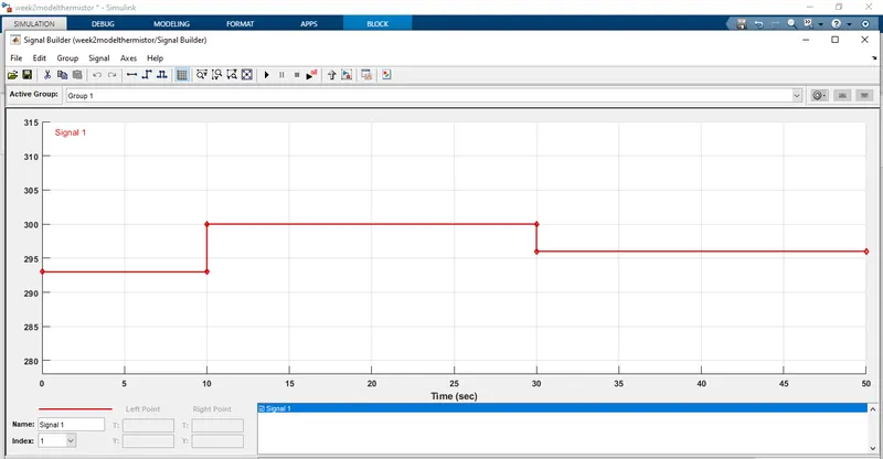
This graph indicates the signal builder where we can input our signal according to the requirement of the blocks. Here from 0 to 10 degree, i have inputted the signal according to the relevant temperature and the same for 10 to 30 and from 30 to 50 as well.
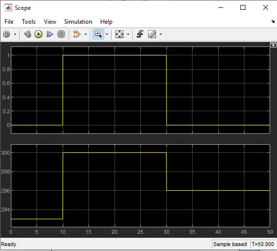
Graph 1 shows the output for the corresponding voltage produced across it according to the resistance values given from the thermometer.
Graph 2 indicates the output from the scope where the x-axis indicates the time value from 0 to 50 seconds whereas the y axis indicates the respective temperature in kelvin which is switched ON the fan only at the time interval of 30 to 50 when it attains the 300 kelvin (25 degrees).