Week -2
AIM:
1. To make a Simulink model of Doorbell using a solenoid block in a situation where the switch is closed for 2 seconds and then closed.
2. To use a thermistor to sense the temperature of a heater & turn ON if the temperature is above 25 C and OFF otherwise.
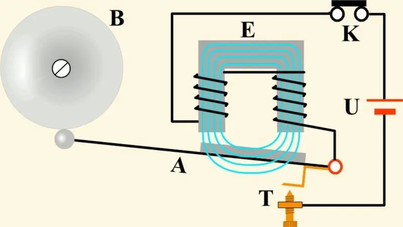
The above-shown image depicts the working circuit of the Electronic doorbell. When the switch is turned on the circuit becomes active and the solenoid activates the plunger which in turn hits the bell.
The solenoid is a simple electronic device that electrical energy into mechanical work. When an electrical current is introduced, a magnetic field forms around the coil which draws the plunger in. The coil is made of many turns of tightly wound copper wire. When an electrical current flows through this wire, a strong magnetic field/flux is created.
Simulink Model:
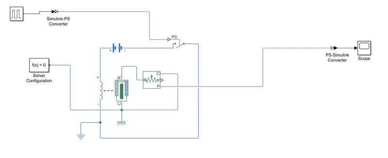
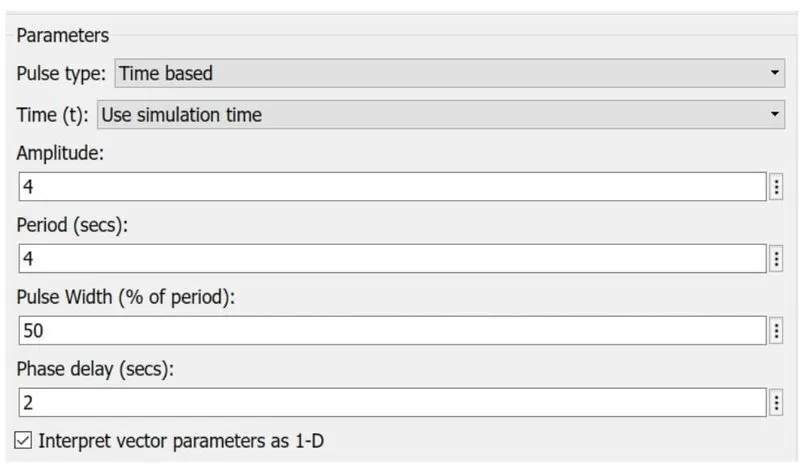
I have given the amplitude as 4. To achieve 2 seconds of phase delay and 2 seconds to ring I have given the time period as 4 seconds with a pulse width of 50%.This is the input signal which is fed into the electrical circuit.The input has to be converted from the Simulink input signal to the Physical signal. This is connected to the switch. One end of the switch is connected to the positive terminal of the battery and the other end is the negative terminal of the solenoid. The negative terminal of the battery is then connected to the positive terminal of the solenoid. Electrical resistance is connected to the circuit and a solver configuration is also added. vThe case 'C' of the solenoid is connected to the mechanical reference and the Plunger 'R' is connected to the Translational conserving ports. The Position 'P' of thetranslational motion consor is connected to the outputThis is the input signal which is fed into the electrical circuit. The input has to be converted from the Simulink input signal to the Physical signal. This is connected to the switch. One end of the switch is connected to the positive terminal of the battery and the other end is the negative terminal of the solenoid. The negative terminal of the battery is then connected to the positive terminal of the solenoid. Electrical resistance is connected to the circuit and a solver configuration is also added.The case 'C' of the solenoid is connected to the mechanical reference and the Plunger 'R' is connected to the Translational conserving ports. The Position 'P' of the translational motion sensor is connected to the output scope and display. Before this, the physical signal is converted into the Simulink signal.
Output:
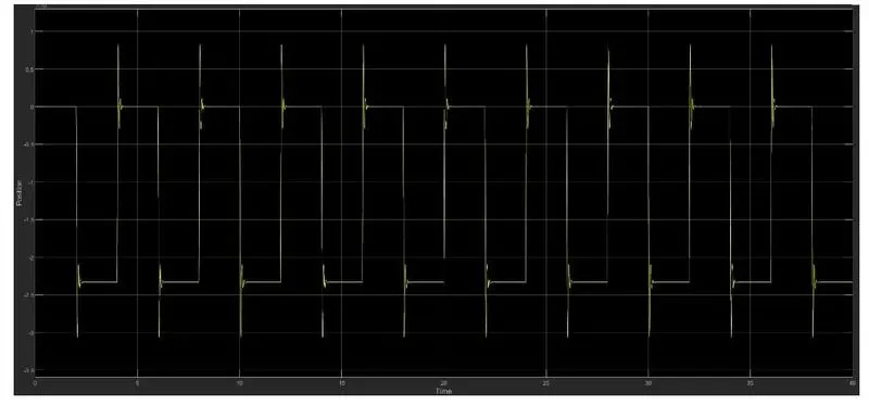
The amplitude/vibration shown at the bottom indicates the bell is ringing at the interval of 2 seconds with phase delay of 2 seconds. The amplitude/vibration at the phase delay line is a concern in the output.
Thermistor Theory:
A thermistor is a resistance thermometer or a resistor whose resistance is dependent on temperature. The term is a combination of "thermal" and "resistor".
There are two types of thermistors: Negative Temperature Coefficient (NTC) and Positive Temperature Coefficient (PTC). With an NTC thermistor, when the temperature increases, resistance decreases. Conversely, when the temperature decreases, resistance increases. This type of thermistor is used the most. A PTC thermistor works a little differently. When temperature increases, the resistance increases, and when temperature decreases, resistance decreases. This type of thermistor is generally used as a fuse.
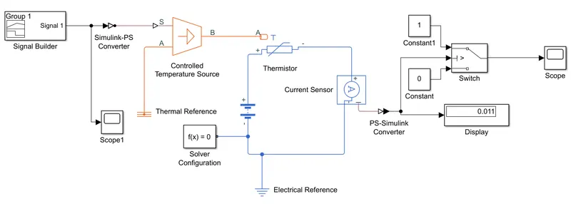
Here the input is fed through the block 'Signal builder'. The input data is given based on the initial conditions provided in the challenge,
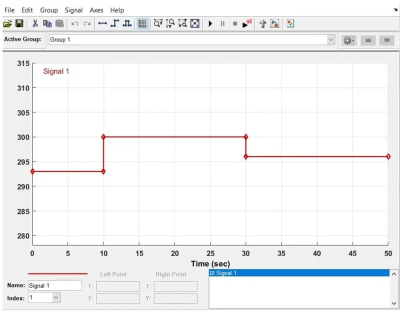
Temperature source: 20 °C from 0 to 10 seconds, 27 °C from 10 to 30 seconds, 23 °C from 30 to 50 seconds Fan conditions: ON if the temperature above 25 °C, OFF otherwise
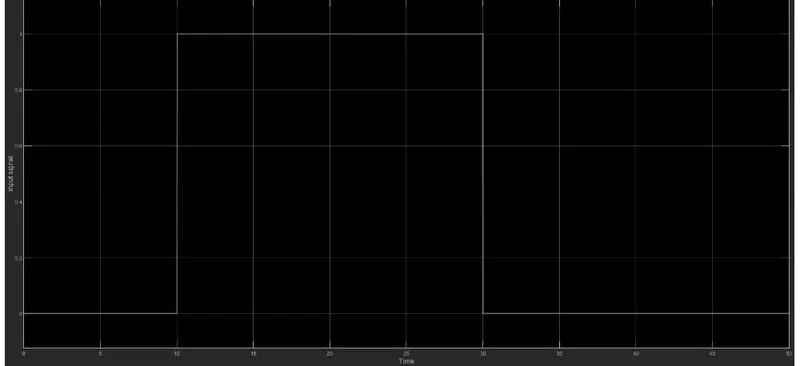
As per the above-mentioned conditions, the input of the Signal builder is incorporated as shown below,
Before this signal is been fed into the Controlled temperature source the settings of the "Simulink Physical signal convertor" have to be modified. In the input handling, the filter input & derivative has to be selected instead of signals this is because here we use two heat source namely "controlled temperature source" (the ideal energy source in a thermal network that can maintain a controlled temperature signals this is because here we use two heat source namely "controlled temperature source" (the ideal energy source in a thermal network that can maintain a controlled temperature difference regardless of the heat flow rate).The positive side of the thermistor is connected to the positive terminal of the battery and the negative side of the terminal is connected to the current sensor (which helps to detect the current flow in the circuit). This is followed by electrical resistance. The value from the current sensor is converted into the Simulink signal using the convertor. The value obtained is displayed in the display block. This just to give the threshold value inside the switch, which has 2 outputs based on 2 conditions if the value is above the threshold value of the output will be 1 and f the value is below the threshold value of the output will be O. The final output is recorded in the Scope.
Output:-