Week -2
1. Make a Simulink model of Doorbell using solenoid block with the following details:
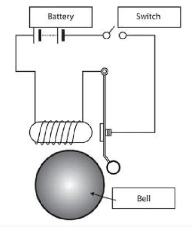
In the above arrangement, when the switch is closed the electromagnet receives electrical power from the battery and pulls the metal arm to hit the bell producing sound.
Create a situation where the switch is closed for 2 seconds and then released. Observe the physical movement of the plunger.
Assume remaining parameters.
Ans :
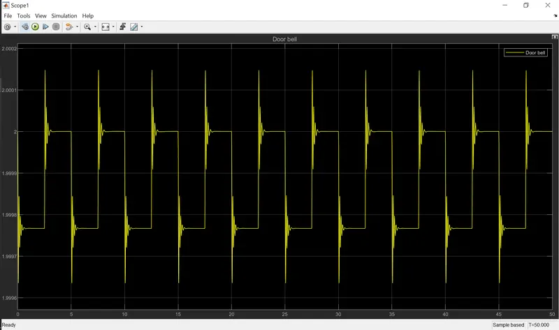
Objective : Based on the movement of the armature, the DOOR bell should ring accordingly.
1.1) Blocks used :
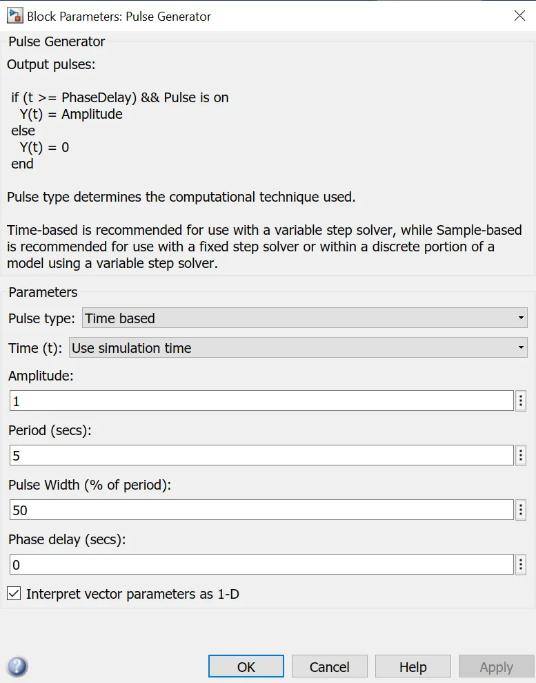
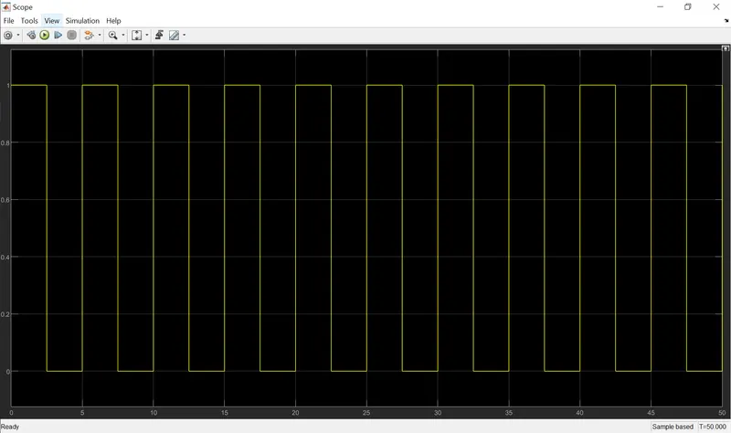
a) PWM generator with the pulse width as 50% and phase delay as 0 seconds
Configuration of PWM generator :
b) Simulink to physical signal conversion block (Simulink-PS Converter)
c) Switch block with PS threshold as 0.5V which is lesser than the amplitude of PWM generator (which is 1V) hence the switch will be in closed state whenever the input (received) PS value is above the given threshold.
d) Electrical battery with internal resistance as 2 Ohm.
e) Solver configuration
f) Electrical reference (electrical ground)
g) Solenoid
Aditional info :
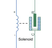
- Solenoid converts electrical energy into mechanical energy
- It containd movable armature, that moves inward and outward(based upon the desing of the armature) everytime the magnetic flux concentration is more.
- When the current flow through the coil magnetic field is generated in it, if you place a metal core inside the coil the magnetic lines of flux is concentrated on the core which increases the induction of the coil as compared to the air core.
h) Ideal translational Motion sensor (Mechanical block set) : This sensor senses the displacement in the armature and the physical signal ports V and P report the velocity and the position, respectively, of port R relative to port C. The measure velocity is positive when the velocity at port R is greater than the velocity at port C.
i) Mechanical translation reference (ground)
j) Physical signal to simulation signal converter
k) Scope to view the graphical representation of the simulation.
1.2) Matlab door bell circuit design :
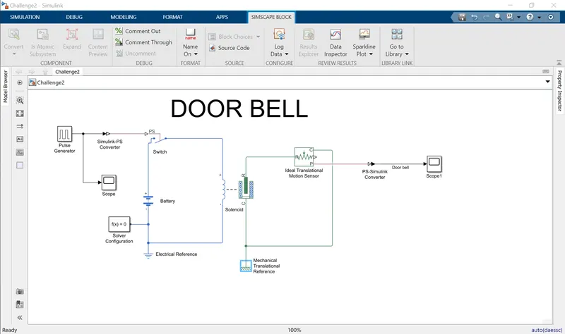
Note : the .slx file has also been added in the attachement.
Overview :
A PWM generator with proper configuration (details of configuration can be found in the "Blocks used' section) has been connected to simulink-PS converter inorder to convert the simulation signal from PWM generator to physical signal which is compatible for electrical switch to recognize and fiunction accordingly.
Electrical switch is provided with source as a form of electrical 12V battery and the negative terminal of the battery was connected to electrical ground along with solver configuration block.
The switch is thereby connected to solenoid (electromechanical block), which gets electrical input based upon the electrical switch status. Everytime the switch is closed the electricity from battery will be passed to the coild of solenoid and thereby produces magentic flux across the coild which then draws the armatures (mechanical energy).
Solenoid's armature "R" is connect to the "R" of the Ideal translation motion sensor block, which sesnes the displacement of the armature and thereby provides the physical signal, which is again connected to the PS-simulink converter inorder to view the output in scope.
1.3) Simulation results :
a) PWM generator :
b) DOOR BELL :
2. Use a thermistor to sense the temperature of a heater & turn on or turn off the fan as per below conditions:
Temperature source: 20 °C from 0 to 10 seconds, 27 °C from 10 to 30 seconds, 23 °C from 30 to 50 seconds
Fan conditions: ON if the temperature above 25 °C, OFF otherwise
Ans :
Objective : Based upon the temperature of the thermisto of the a heater, the fan should be turn ON or turn OFF.
2.1 Blocks used :
a) Either Signal builder Or Repeating Sequence Stair - To provide the temperature input to the thermistor.
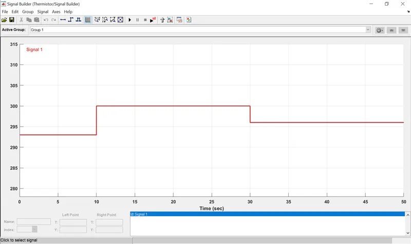
Option 1 : If signal builder is used then the following configuration should be done in order to get appropriate graph -
i) At time 0s - Temperature 293K
ii) At time 10s - Temperature 300K
iii) At time 30s - Temperature 300K
iv) At time 30s - Temperature 296K
v) At time 50s - Temperature 296K
Hint 1 : By maually giving customized signal by giving time stamps and corresponing temperature.
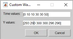
Hint 2 : By selecting each time staps on default signal builder and there by editng the "T" and "Y" values which you can find under "Left point" section.
In either way you will be getting the following graph as output (which is in actual is an input to thermistor) :
Option 2 : Using Repeating sequence stair block. Provide the temperature values in 1D array and you will get the desired output which can be fed to thermistor.
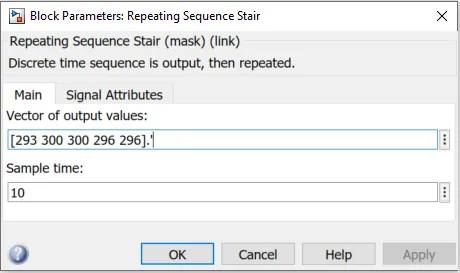
Output of using repeated sequence stair :
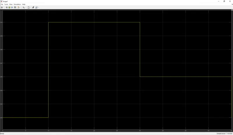
The end result will be same if either of the block were used to fed the input temperature to thermistor.
b) Simulink to PS converter : The Input signal unit for this block shall be made as "K" to provide the temperature input to thermistor.
c) Controlled temperature source : The Controlled Temperature Source block represents an ideal source of thermal energy that is powerful enough to maintain specified temperature difference across the source regardless of the heat flow consumed by the system. The temperature differential across the source is directly proportional to the signal at the control port S, which means whatever input that has been received from Simulink to PS converter same will be used by Port S. The block positive direction is from port A to port B. This means that the temperature differential is determined as TB – TA, where TB and TA are the temperatures at source ports. (More details can be found in Matlab documentation.)
d) Solver configuration : This block is mainly needed if any physical network has been used in the model. The solver configuration block specifies the solver parameters that model needs before begining the simulation. (More details can be found in Matlab documentation.)
e) Thermistor : To generate the temperature dependance resistance in order to control the fan.
f) Battery
g) Thermal Reference
h) Electrical Reference
i) Voltage sensor
j) Resistor
k) Constant (1 and 0)
l) Switch
m) Display
n) Lamp
2.2) Matlab temperature dependant fan ON-OFF (using thermistor) circuit design :
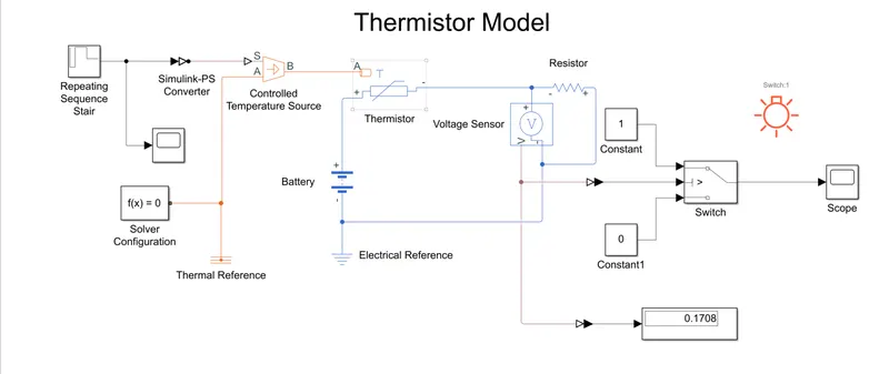
Note : the .slx file has also been added in the attachement.
Overview :
Receiving the temperature inputs from Repeating sequence stair/signal builder, controlled temperature source then evaluates the temperature different and thereby provides it to the NTC (negative temperature co-efficient) thermistor.
the NTC thermistor, as the temperature increases, resistance decreases (just like ohms law, the resistance is inversely proportional to temeperature). Thus the voltage sensor which has been connected parallel to the thermistor will measure the voltage across the thermistor and the addional resistor, with resistance of 15 ohm, is connected parallel to the voltage sensor to evaluate the current and thereby provide the obtain the value that will be fed as input to switch.
Based upon the thershold value configured inside the switch, the selection of logic 1 or logic 2 will be selected.
In the above model, the resistance value was given as 15 ohm and thereby it had caluculated the current (just like simplified thevenin's theorem) based upon the obtained value at 'V" of voltage sensor, the switch will operate accordingly and to indicate the operation, an optional lamp was added to observe the on and off of the switch.
1.3) Simulation results :
a) Fan On-OFF operation :
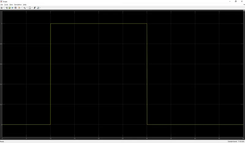
Thus based upon the temperature and thereby obtained resistance and current, the fan ON-OFF operation can be performed.