Week -2
Aim : To make simulink model of a doorbell using solenoid block.
Door Bell: Simulink model:
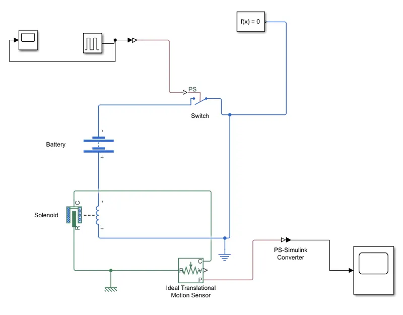
Simulink model explanation:
The pulse generator is used to create the square wave pluse at regular intervals.The block waveform parmeters amplitude,pulse width,period and phase delay,determine the shape of the output waveform.
The switch block used is controlled by the external physical signal.If the external signal is greater than the threshold parameter than the swithc will get closed otherwise the switch is open.
The ideal translation sensor is connected with solenoid block R to observe the movement of the plunger.
Scope is connected with the ideal translation sensor to get the output.
PS -Simulink converter is used to convert the physical signals to simulink signal.
The positive terminal of the switch is connected to swicth and the negative terminal is connected to the electrical reference.
Solver configuration each physical network represented by a connected simscape blocks requires solver setting information for simulation.
Results:
Door bell.
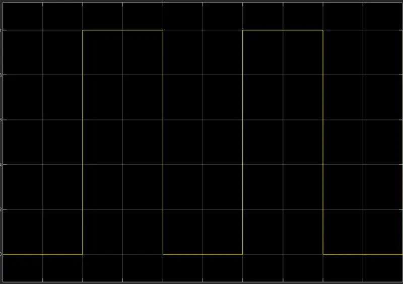
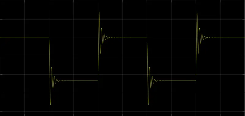
Time period given is 2 seconds to the pulse generator to open/clsoed the switch.When the switch is closed the solenoid blocks received electrical power from the battery and the plunger move from R to C to hit the bell and produces sound.
2: Thermistor
Aim : Create a Simulink model of thermistor to sense the temp of the heater and turn on and off the fan.
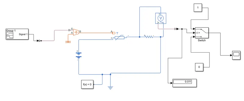
In the first block we use the input block wherein we using a signal builder to give an input that is filtered 20deg C from 0-10 secs , 27deg from 10-30sec and 23deg from 30-50 secs. The output of the signal buider is converted to physical signals by means of a simulink PS converter.Now the controlled temp source that will deliver the filtered input into the thermistor in resp time intervals and it is also grounded to the thermal reference.The thermistor is given the temp input that will vary in specified time intervals.The thermistor is connected to the battery source and a resistor in series and voltage sensor connected in parallel .The voltage sensor and resistance connection is for finding the threshold voltage which is the triggering values to make the fan ON/OFF Here it is given at 25deg. We will run the model to find out the threshold value at 25deg and the output value is displayed in the display block the threshold value is 0.011.
Now we can either show the required results of switch ON/OFF of the fan by just designing with the constant 0 and1
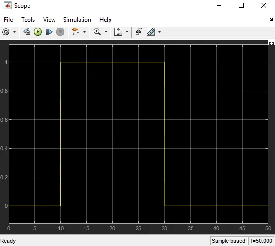
The ouput result you can see from the above plot graph that
0-10 sec = fan is off (constant 0)
10-30sec = fan is ON ( Constant 1)
30-50sec = fan is off (constant 0)
This is because it is said that the fan should be on only above 25deg and that is happening only in 10-30sec at 27Deg.