Week -2
Objective1
To create a Simulink model of a calling bell with a 2 sec of delayed ringing and to observe the movement of the plunger.
Simulink blocks used
- Pulse generator
- Simulink –PS converter
- Solenoid
- Electrical reference
- Dc source
- Solver configuration
- Ideal translational motion sensor
- Mechanical translational reference
- PS-simulink converter
- Scope
Working
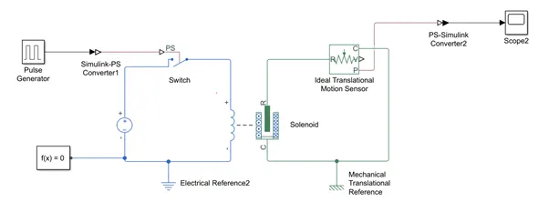
The pulse generator is given a 2 sec delay and is fed to the solenoid through a Simulink PS converter.
The converter will change the incoming Simulink signal to the necessary physical signal.
Then the signal goes to the solenoid with the plunger attachedment. As per the weight of the plunger the output varies. So weight of the plunger is important in this case.
The circuit is powered by the Dc source for which the voltage value is needed to activate the circuit value. This whole circuit is then connected to the electric and mechanical reference respectively.
The R of solenoid is connected to the R of the translational motion sensor; the C of solenoid to the C of the sensor and the P of the sensor to the Ps –simulink converter and then to the scope.
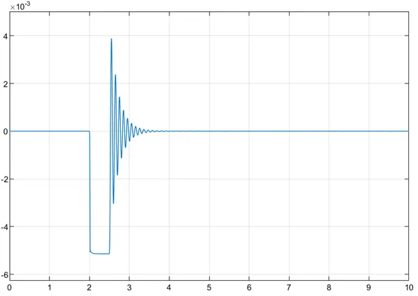
The scope gives the output with respect to the input of the Pulse generator and depends greatly upon the plunger weight.
Circuit connection and output
Challenge2
Objective
To create a simulink model which uses a thermistor to sense the heat to follow the conditions thereby turning on the fan whenever the temperature reaches 25 C.
Simulink blocks used
- Signal builder
- Simulink- PSConverter
- Controlled temperature source
- Thermistor
- References
- Resistor
- Voltage sensor
- DC voltage source
- Scopes
- Ps to Simulink converter
- Switch
- DC motor
- Battery source
- Rotational motion sensor
Working
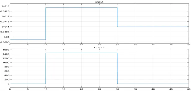
The signal builder is constructed as per the temperature to time given. (ie., 20 °C from 0 to 10 seconds, 27 °C from 10 to 30 seconds, 23 °C from 30 to 50 seconds).
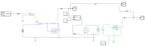
Then the signal is fed to the controlled temp.source then to the thermistor.
The thermistor used is a NTC type, so that the circuit is added with the resistor. Then the voltage sensor to measure the voltage is attached.
This circuit is then connected to the Dc Source and with its respective references.
Then the solver configuration is connected to the circuit. A connection from the voltage sensor is then connected as the input to the Ps-simulink sensor and then to the scope.
The output of this circuit is noted down to the 25 C and then fed to the 2nd circuit that is in connection with the 1st circuit.
A DC motor is connected to the 1st circuit and the R and C ports are connected to the respective rotational motion sensor and then is fed up to the converter and to the scope.
The final result is shown in the 2nd scope attached.
Circuit diagram
Output
https://drive.google.com/drive/folders/1Ls3ppTK3x8-n7QIr-p848qFtS0beuNyG?usp=sharing