Week -2
https://drive.google.com/drive/folders/1g0JkZ8I6N6Re1Z8xiMEPETUPtVlOBZmP?usp=sharing
Google Drive Model Link(Above Link)
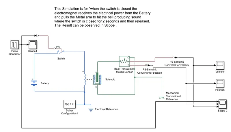
1. This Simulink Model ( simulink file uploaded in Google Drive and link is attache & also Screen short of model as below) is designed and simulated to observe the physical movement of Plunger when the switch is closed (for 2 secsonds), the electromagnet receives electrical power from battery and pulls the metal arm to hit the bell producing sound.
 |
Pulse Generator:
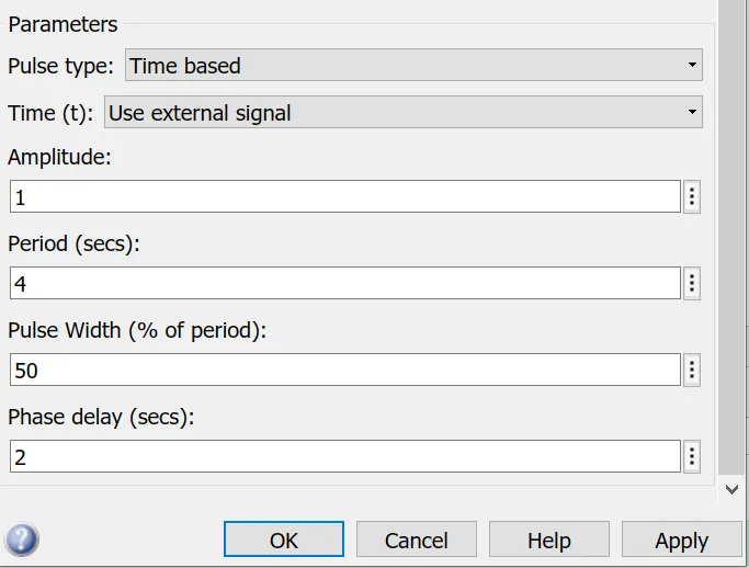
- The Pulse Generator block generates square wave pulses at regular intervals. The block waveform parameters are amplitude, pulse width ,period and Phase delay .
- In this simulation parameters set for pulse generator as below for a period of 4 Sec , Amplitute as 1 to triger(Control Supply) the Switch to ON , So the Solenoid Coil can get electrical power Supply from Battery with a delay of 2 sec once the Simulation starts .
- The Pulse Width kept as 2 sec as We have to continuously give the Battery Supply to Solenoid Coil for 2 sec.
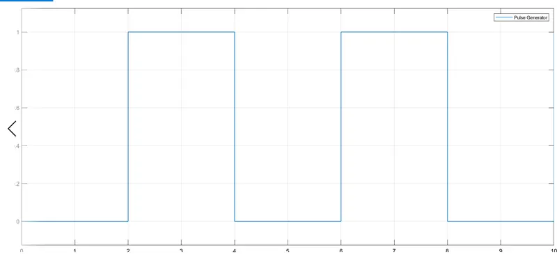
The Output of the scope can be visulaised from Scope1 .
It starts with a time delay of 2 secs once after the Simulation runs as phase delay parameter set as 2 Sec.
Switch:
The block represents a switch controlled by an external physical signal. If the external physical signal PS is greater than the threshold, then the switch is closed, otherwise the switch is open.
Thresold: 0.5 (As The Pulse Output magnitude go above 0.5 , The Switch gets ON )
SImulink -PS Converter:
As Pulse Geneartor is a Simulink Block and and Switch,Battery & Solenoid are Physical Blocks , SO to make Output of Pulse generator needs to be converted into Physical Signal ,The purpose of this block to convert the output of Pulse Generator in physical Signal for this model.
Battery:
This block models a battery. The Nominal Voltage Set as 12V. The Purpose to use Battery is to give electrical Power to the coil of Solenoid inorder to Energize/actuate the momentary part .(as per force generated due to electro magnetic Induction inside Solenoid)
Solenoid:
- This block implements the electrical and mechanical characteristics of a solenoid.
- The Coil part Rated DC is 12 V Same as Battery nominal Voltage.
- Once the Coil part enegizes , It generates force due to Ilectromagnetic Induction and the Momentary part of Solenoid Moves because of this Force and hit the bell .
Ideal Translational Motion Sensor:
- This Block Measures velocity and displacement in a mechanical translational network.
- This is considered as an ideal Sensor .(With out Intertia,energy consuption,Friction & delays etc)
-
The physical signal ports V and P report the velocity and position, respectively, of port R relative to port C. The measured velocity is positive when the velocity at port R is greater than the velocity at port C.
PS-Simulink Converter:
- This Blocks used to convert Physical Signals (Output of Translational Motion Sensor) to simulink output signal.
- As scope is part of Simulink block set. So in order to see the Output we have to use this block to fulfill the required purpose.
Scope:
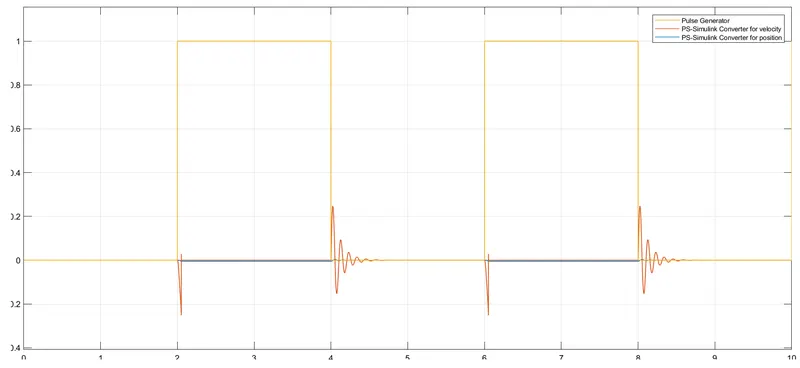
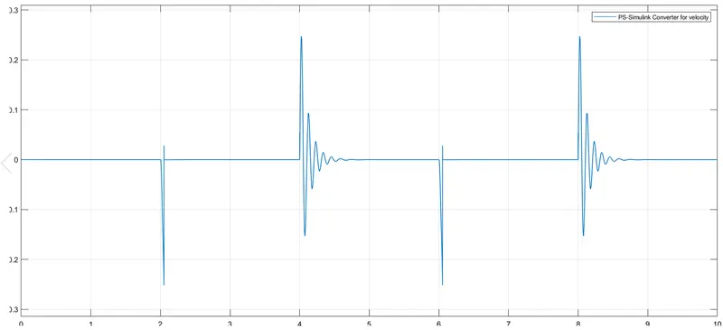
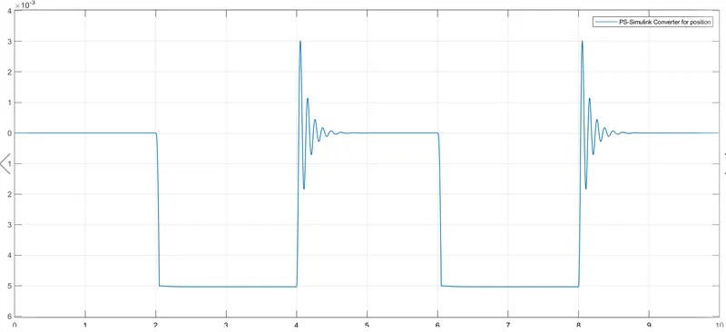
- Four scopes used in this Model. Out of Four Three are used to show Individual Signals and Scope2 is used to Input (Pulse nput) and Output of Translatinal Motion Sensor (I.e Velocity & position) all Together for better Observation.
Scope 2:
Velocity:
Position:
Electrical Reference:
- The Electrical Reference block represents an electrical ground.
- As a model with electrical elements must contain at least one Electrical Reference block , SO this block is used to fulfil the Purpose.
Mechanical Translational reference:
- The Mechanical Translational Reference block represents a reference point, or frame, for all mechanical translational ports.
- All translational ports that are rigidly clamped to the frame (ground) must be connected to a Mechanical Translational Reference block. So this block is used to fulfill the Purpose.
Conclusion/Observation:
Once the Pulse Generator Turns on the Switch by giving Pulse input, The Coil of the Solenoid Gets power from Battery and energized resuling an Electromagnetic force generation which moves the Momentary part of solenoid and hits the Bell. The Momentary part of Solenoid stay in touch with Bell Until the Coil not deenegize (here this time duration is 2sec for this model). Again The Cycle repeats in an interval of 2 secs and it Continues.
2. The objective of this Simulation to measure or sense the temperature from a temperature source and to Turn on the FAN above a perticular temperature which is relevant to a real time application similar like Transformer Cooling or any automated system design where cooling necessary above certain level of temperature rise.
Exact Requirement of this Simulation:
Temperature source:
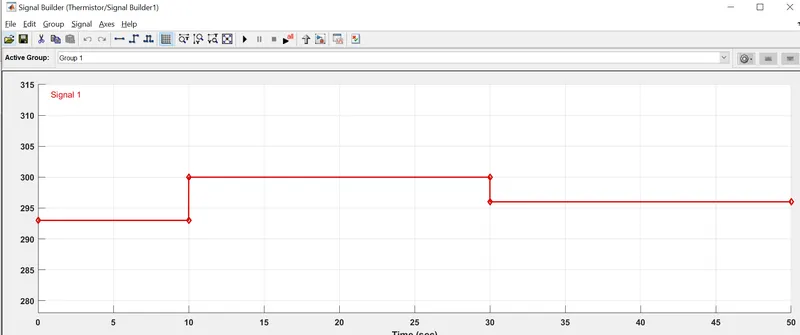
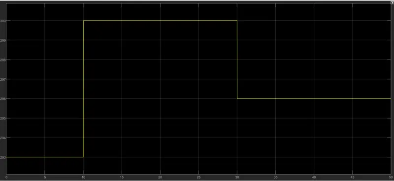
0 to 10 seconds :20 °C (293.15K in absolute scale)
10 to 30 seconds :27 °C (300.15K in absolute scale)
30 to 50 seconds :23 °C(296.15K in absolute scale)
Fan status :
ON ,if the temperature above 25 deg C
OFF, otherwise (i.e below 25deg C)
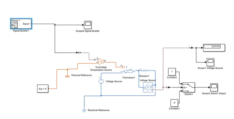
The simulation model is made as shown in above figure, (Screen short of actual Model).
Signal builder:
This block is used to make one customized or desigred signal w.r.t Time as our requirement is to get three different Temperatures for three diffrent Time duration.
Scope-2
This block is used to visulise or observe the Signal Builder Output wheather it meets the requirement or not.
Controlled Temperature Sorce:
- This is a simscape library block .
- The Controlled Temperature Source block represents an ideal source of thermal energy that is powerful enough to maintain specified temperature difference across the source regardless of the heat flow consumed by the system.
- Connections A and B are thermal conserving ports corresponding to the source inlet and outlet, respectively. Port S is a physical signal port, through which the control signal that drives the source is applied.
- The most important thing is to note that "The temperature differential across the source is directly proportional to the signal at the control port S." So we can able to generate a temperature Source as per the Control signal fed at port S from signal buider.
- As the Signal Builder block is simulink block & Controlled Temperature source is a simscape/physical block , SO Simulink-to PS converter is used at signal builder output.
Thermistor:
- This is the main device whose physical behaviour(physics) is the most important part of this model/simulation.
- This is used as temperature sensor by chaging it's internal resistance with respect to temperature variation.
- A thermistor is a resistance thermometer, or a resistor whose resistance is dependent on temperature. The term is a combination of “thermal” and “resistor”. It is made of metallic oxides, pressed into a bead, disk, or cylindrical shape and then encapsulated with an impermeable material such as epoxy or glass.
- There are two types of thermistors: Negative Temperature Coefficient (NTC) and Positive Temperature Coefficient (PTC). With an NTC thermistor, when the temperature increases, resistance decreases. Conversely, when temperature decreases, resistance increases. This type of thermistor is used the most.
- Here the used thermistor block is also an NTC type thermistor using the B-parameter equation
- The resistance at temperature at T is R=R0eB(1/T−1/T0).T0: intial value of Temperature.
- R0is the nominal resistance at the reference temperatureT0 . B is the characteristic temperature constant.
Resistor , Voltage Source, Voltage sensor:
- One External Voltage source block is used in series with Thermistor and a resisor in series.
- The Purpose of using a Voltage source and a resistor is to make one criteria to turn on the FAN at certain level of Temperature based on Variation of internal resistance of Thermistor.
- There is a current flow from voltage source to throuh thermistor and extrnal Resistor. The Current flow varries based on Thermistor Internal Resistance change. when the Temperature go beyond 25 deg C, The current in this series Circuit increases (As thermistor internal resistance will reduce by property of NTC)resulting increasing in the Voltage drop across external Resistor .(R , is Const. if I increases , IXR=V will increase ). The Voltage acrosss the external resistor Can be mesured by a Voltage source.
- The Voltage Output fed to a switch through a PS-Simulink Converter as Switch is a Simulink block.
Switch:
- This Switch has one Output .3 ports at Input side. Port-2 is Control Port or Criteria .
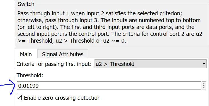
- Switch selects the Input 1 ,when the Value at Port 2 > thresold (i.e 0.01199 for this model set based on the observation of Voltage sensor output at 25 deg C input ) and when Port2 is less than Thresold , It connects the Input port 3 as Output.
- Constant 1 can be considered as Switch ON or can be connected to Sorce to turn onany external FAN.
- Constant 2 can be considered as Switch OFF or No Supply to FAN.
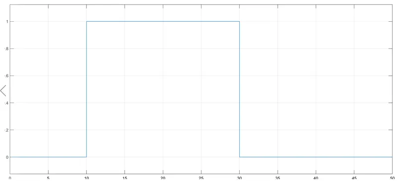
Switch Output Can be observerved from Scope-3 Output which meets our final Requirement (i.e the FAN should ON above a Temperature Level of 25 deg.C)
- One Electrical Common Reference is used for all Electrical Componets in the physical Model and Thermal Reference is used for Ideal Temperature sorce .
Conclusion:
It can be observed that the FAN gets ON (I.e Switch ON in this Model) exactly above any temperature beyond 25 deg.C
In this Model i.e between 10 to 30 sec. Remaining time the switch is OFF , We can say the FAN is OFF.
The major Focus/objective understood from this model is to use of Themistor or modeling of any Physical model using Themistor (NTC) which Practically Co-relates many applications like Transformer Cooling, Heat Sink Cooling in Inverter, UPS or any Power electronics Application , Can be applicable for Many automobile and Industrial Application where Temperature is a major criteria to turn on/off another Process or Indication .
Temperature source:
0 to 10 seconds :20 °C (293.15K in absolute scale)
10 to 30 seconds :27 °C (300.15K in absolute scale)
30 to 50 seconds :23 °C(296.15K in absolute scale)
Fan status :
ON ,if the temperature above 25 deg C
OFF, otherwise (i.e below 25deg C)
Google Drive Link for Model (For Q1 & Q2 both Models uploaded) :
https://drive.google.com/drive/folders/1g0JkZ8I6N6Re1Z8xiMEPETUPtVlOBZmP?usp=sharing