Week 14 challenge
PROJECT NAME: BUTTERFLY VALVE ASSEMBLY:
INTRODUCTION:
Siemens UG NX CAD, commonly referred to as NX, is a powerful integrated solution for computer-aided design, manufacturing, and engineering analysis (CAD/CAM/CAE). It is developed by Siemens Digital Industries Software, a division of Siemens AG.
Key features of Siemens UG NX CAD include:
- Design: It offers advanced 3D parametric modeling capabilities for designing complex parts and assemblies.
- Simulation: NX provides simulation tools for structural, thermal, motion, and Multiphysics analyses to validate designs before manufacturing.
- Manufacturing: It includes CAM (Computer-Aided Manufacturing) functionalities to generate tool paths for CNC machines, ensuring efficient and accurate manufacturing processes.
- Collaboration: NX supports collaborative design and data management, allowing teams to work concurrently on projects and manage design revisions.
- Integration: It integrates with other Siemens PLM Software products and third-party applications, facilitating a streamlined product development workflow.
Overall, Siemens UG NX CAD is widely used in industries such as automotive, aerospace, machinery, and consumer products for its comprehensive feature set and robust capabilities in product design and manufacturing.
We have to design and develop for Butterfly Valve Assembly by using UG NX CAD Software. first we have create the design and develop for butterfly valve parts After completing the parts design then, assemble the all parts by using assembly command .
What is Butterfly Valve:
A butterfly valve is a type of quarter-turn valve used to regulate fluid flow within pipelines. It derives its name from the wing-like disc that rotates inside the valve body to control the flow of fluid. Here are some key characteristics and features of butterfly valves:
Operation: Butterfly valves operate by rotating a disc or vane perpendicular to the flow direction. When the disc is turned parallel to the flow, it allows for unrestricted flow, and when turned perpendicular, it restricts or stops flow.
Design: The valve consists of a circular disc mounted on a spindle or shaft in the center of the pipe. This disc can be either fully or partially open or closed depending on the desired flow control.
Types: Butterfly valves come in various types based on their design and application:
- Wafer Type: These valves fit between flanges and are held in place by bolts through the flange holes.
- Lug Type: Lug-style valves have threaded inserts at both sides of the valve body, allowing them to be installed between two flanges.
- Double Offset: These valves have a disc offset from the centerline of the valve body and shaft, reducing wear and extending the valve's life.
- Triple Offset: The sealing mechanism in these valves is designed with three offsets to ensure tight shut-off and minimal wear.
Materials: Butterfly valves can be constructed from various materials such as stainless steel, carbon steel, ductile iron, and PVC, among others, to suit different applications and fluid types.
Applications: They are commonly used in industries such as water treatment, HVAC (heating, ventilation, and air conditioning), chemical processing, and power generation due to their versatility, ease of operation, and relatively low cost compared to other valve types.
In summary, butterfly valves provide efficient flow control in pipelines and are valued for their simplicity, lightweight construction, and ability to quickly open or close with minimal effort.
Butterfly valve is used to allow or stop the fluid flow on pipe line. The valve open or closed operation is used on the leaver. this type of valves are used in Oil & Gas ,Water industry.
Various type of butterfly valves are there,
1.Leaver operated
2.Gear operated
3.Automation Butterfly valve
4.Flange type connection Butterfly valve
5.Wafer type connection Butterfly Valve
Before create the Assembly we have do create the butterfly valve parts, Like ( Body, Disc, Shaft, Retainer, Nut, Bolt, Leaver)
Mastic Data or Master Sketch:
In the context of UG NX CAD (Siemens NX CAD), "Mastic Data" or "Master Sketch" typically refers to foundational data or reference geometry used in the design process. Here's how each term is typically understood within NX CAD:
Mastic Data or master sketch is used to design and develop the product is accurate dimension and design as per standards.
What is GD&T:
GD&T stands for Geometric Dimensioning and Tolerancing. It is a system for defining and communicating engineering tolerances and allowable variations in form, size, orientation, and location of features on a part or assembly. Here are the key aspects of GD&T in design:
Standardization: GD&T provides a standardized method for specifying and interpreting engineering tolerances. It uses symbols, feature control frames, and specific rules to communicate these tolerances effectively.
Features: It applies to various features such as holes, slots, surfaces, and profiles. Each feature can be defined in terms of its size, orientation, form (shape), and location relative to a datum reference frame.
Benefits: GD&T allows for more precise control over part dimensions and relationships, leading to improved interchangeability, assembly fit, and functionality.
Symbols and Annotations: Symbols used in GD&T include:
- Datum Feature Symbols: Indicate which part features are to be used as datums.
- Feature Control Frames: Specify tolerance zones and allowable variations.
- Modifiers: Provide additional information about tolerance requirements, such as maximum material condition (MMC) and least material condition (LMC).
Applications: GD&T is widely used in industries such as automotive, aerospace, manufacturing, and engineering design. It is crucial for ensuring parts and assemblies meet functional requirements while accommodating manufacturing processes and variations.
International Standards: The principles of GD&T are governed by international standards, primarily ASME Y14.5 (in the United States) and ISO 1101 (internationally), which provide guidelines and rules for implementation.
In summary, GD&T plays a critical role in modern mechanical design by specifying allowable tolerances with greater clarity and precision than traditional dimensioning methods, thereby enhancing the quality and functionality of manufactured parts and assemblies.
Body :
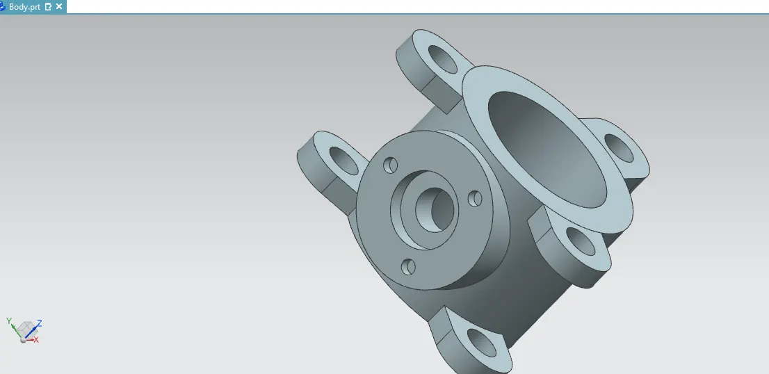
Refer the Master sketch for Butterfly Valve body , design and develop the Body part. Select the Sketch and create the datum to draw circle in given value of mastic data and extrude the circle to convert 3D View.
Select the circle in 280 mm and 194 mm diameter and extrude the both circle in 225 mm. The Hollow cylinder shape would be created .that is body of butterfly valve.
Then create the ear on the butterfly valve. create the datum and select the sketch create the Circle in 100 mm dia and 47 mm dia from center of 175 mm distance. after design the ear sketch and make the pattern in 3 nos in 120 degree angle.
After create the pattern to move the ear in both side of body edges. finally extrude in 32 mm thick.
Now create the side hole in body that is disc and shaft holding area.so create the datum 160 mm distance from center of axis. after that select the sketch and pick the datum so sketch would be create in side hole datum.
Then create the circle in 200 mm dia ,100 mm dia 56.2 mm dia and extrude in body of the valve by using unite command. finally three holes are created in the side part .select the circle in 20.3 mm dia the pitch circle diameter PCD is 150 mm, after that we have select the pattern and show on three holes in 120 deg angle.to extrude the hole in -15 mm subtract. The hole depth would be created.
Finally create the Draft and apply the GD&T in Valve Body.
Disc:
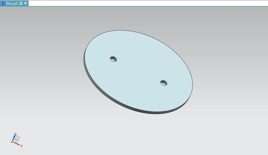
Design and develop the disc part. Select the Sketch and create the datum to draw circle in given value of mastic data and extrude the circle to convert 3D View.
Select the Ellipse give the value of 102 mm and 96.9 mm radius and give the hole circle value is 12.5 mm in 50 mm distance from the center of axis .we have two hole so create the circle in both sides.
Extrude the both ellipse in 6 mm thick. The disc would be created. finally create the Draft and apply the GD&T in Valve Body.
 .A
.A
Shaft:
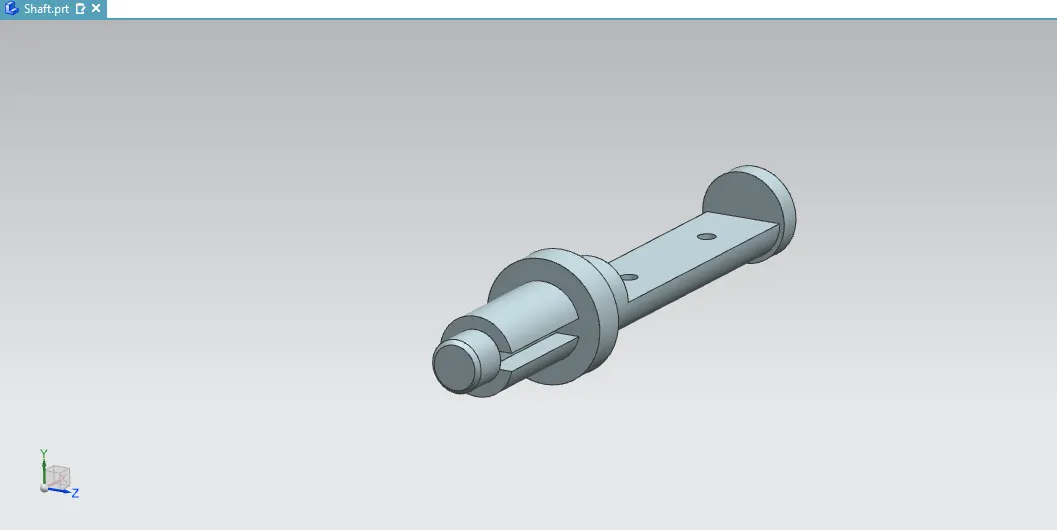
Select and create the Sketch to draw the line . The line dimension value based on mastic data ,and half size of thickness value would be considered on master sketch dimensions.
Then Revolve the sketch on 360 deg to create the shaft, and make under cut on head and tail end.
Select the rectangular 193.8 mm length and width 28 mm and extrude the rectangle to subtract the Boolean and say ok in tail end of the shaft.
Same Scenario would be created on top side of the shaft .Select rectangle 86 mm length and width 12.6 mm in center of the axes and extrude the rectangle to subtract the Boolean and say ok in Headed the shaft.
Now we were create two circle in tail side of under cut. select the circle command to create the two circle in 12.5 mm dia and 100 mm distance in both circles.
Select the extrude to pick on the circle then mention length on -28 mm and subtract the Boolean. The Hole will be created. Finally create the Draft and apply the GD&T in Valve shaft.
Retainer:
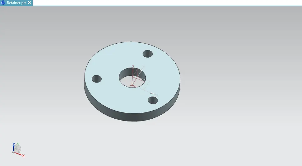
We have to design that retainer plate for butterfly valve. The retainer plate is used to fix the top on the valve .because it is used to connect and fix the shaft and leaver.
refer the master sketch to create the circle on 200 mm dia, inner dia is 56 mm ,PCD - 150 mm. Then create the Hole circle in 20.3 mm .
Then Select the Pattern command to create the another two circle in 120 deg angle. After that select the extrude to pick the sketch and extrude the 25 mm thickness. Now create the Draft and apply the GD&T.
Leaver:
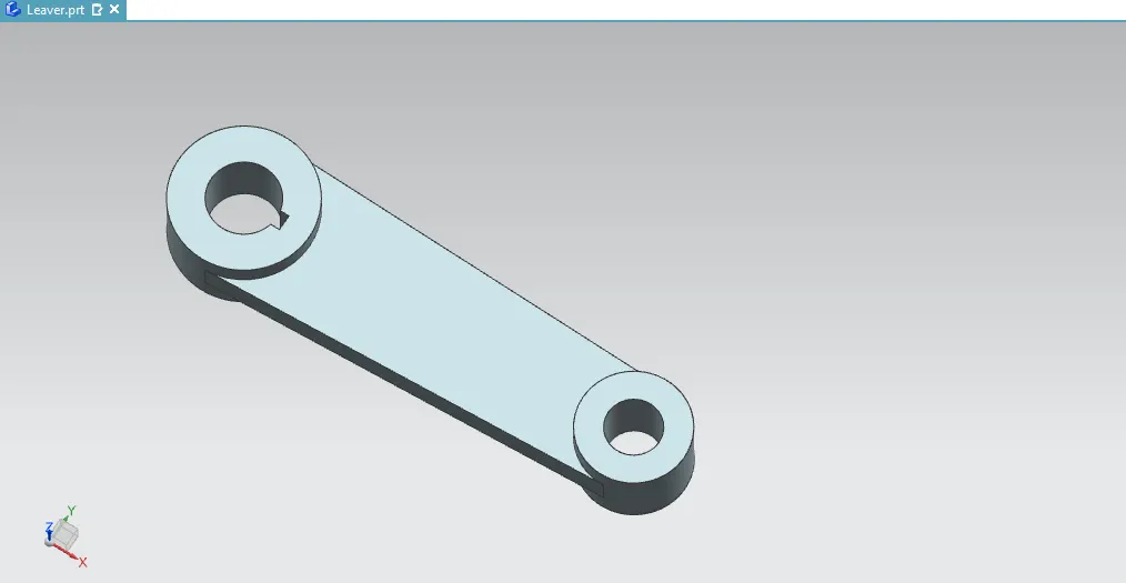
Leaver is Major part of butterfly valve. Because its only used to open and closed for butterfly valve.
Select the Circle and create the circle on 112.5 mm dia and 28.15 mm dia then create the under cut for the circle to use in line option to create the line in horizontal and vertical direction to equal to center of axes .then trim the unnecessary lines by use in Quick trim Option. The sketch would be created on top side hole.
Same scenario would be created on the bottom side sketch. Create the circle on 87.5 mm dia and 43.8 mm dia Next extrude the sketch in 62.5 mm thick to show on bottom and top head holes. Now we have center of body in leaver.so create the sketch to create on two tangent line in both sides and create the arc in two circles to connect the both lines.
Now extrude the lines in 25 mm thick using in unite command and say ok. Then Create the Draft and apply the GD&T also.
Bolt:
Select and create the Sketch to draw the line . The line dimension value based on mastic data ,and half size of thickness value would be considered on master sketch dimensions.
Then Revolve the sketch on 360 deg to create the blot ,and make Chamfer in 3mm on bottom end.
Select the rectangular to create in head of the Bolt . 3.5 mm width and length is 28 mm then extrude the rectangle to subtract the Boolean and say ok .
Nut:
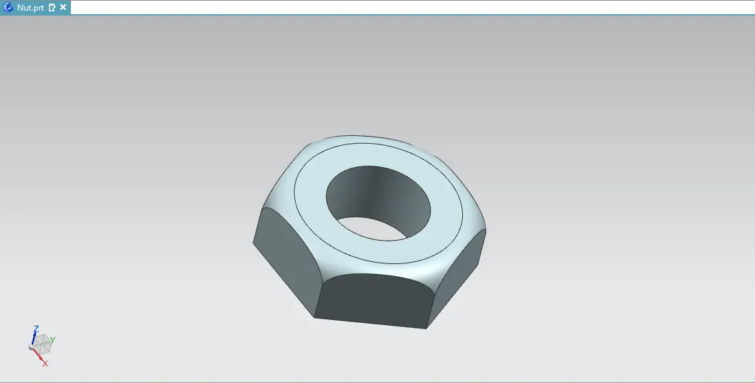
Make nut to design and develop by using UG NX Cad. So first create the polygon then select the line to create in 34.5 mm distance from center of axis. use pattern we have create the 6 lines in 60 eg angle. the trim on unnecessary lines. now create the circle on center of polygon. The circle diameter is 37 mm. then extrude in 25 mm thickness.
now we have create the bend on nut top side. select the datum and create in 34.5 mm from center of axis then create the sketch and draw the line and arc. next trim in unnecessary line. now revolve the sketch and subtract the Boolean .
The nut would be created then create the draft and apply the GD&T .
How to assemble the All Parts:
Open on New Page and select the Assembly option then select the location and say ok. the Assembly file would be created. Now add on all parts file in assembly file and select the move component by using on move the all parts all right position.
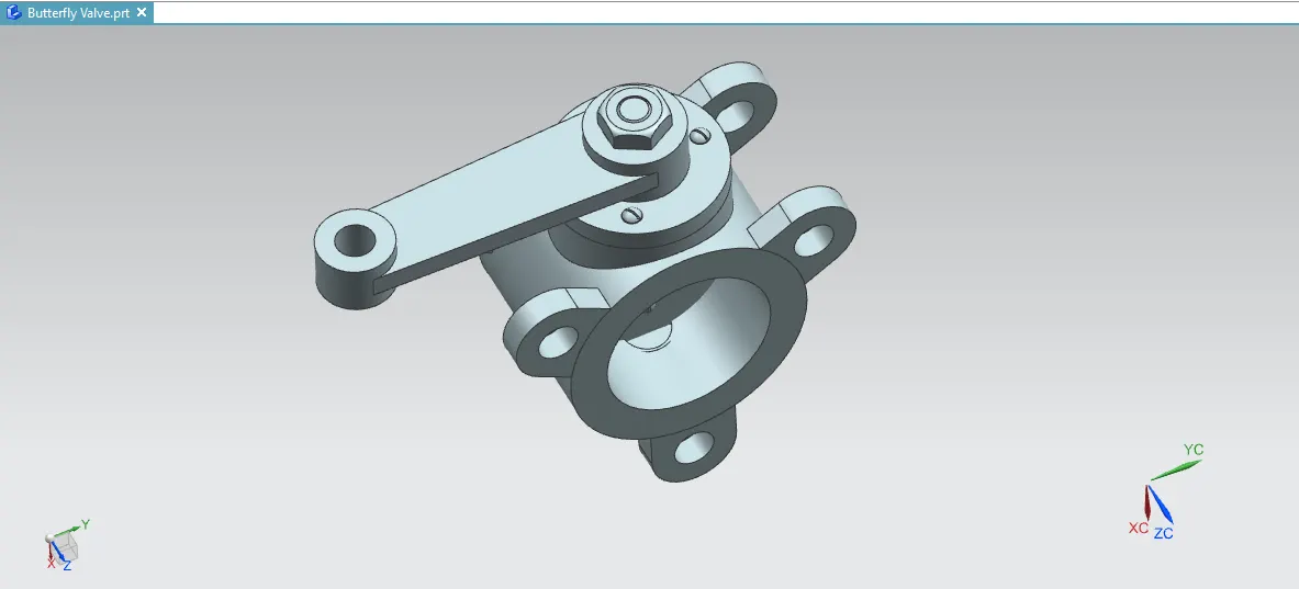
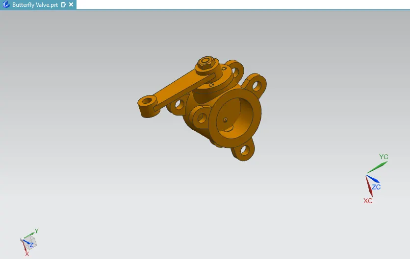
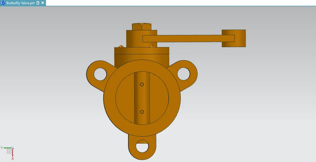
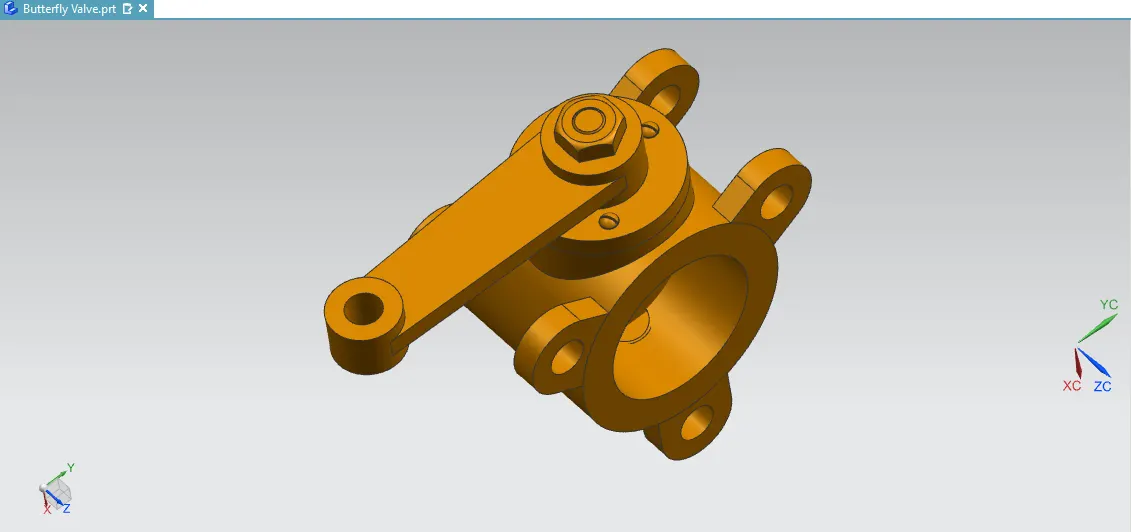
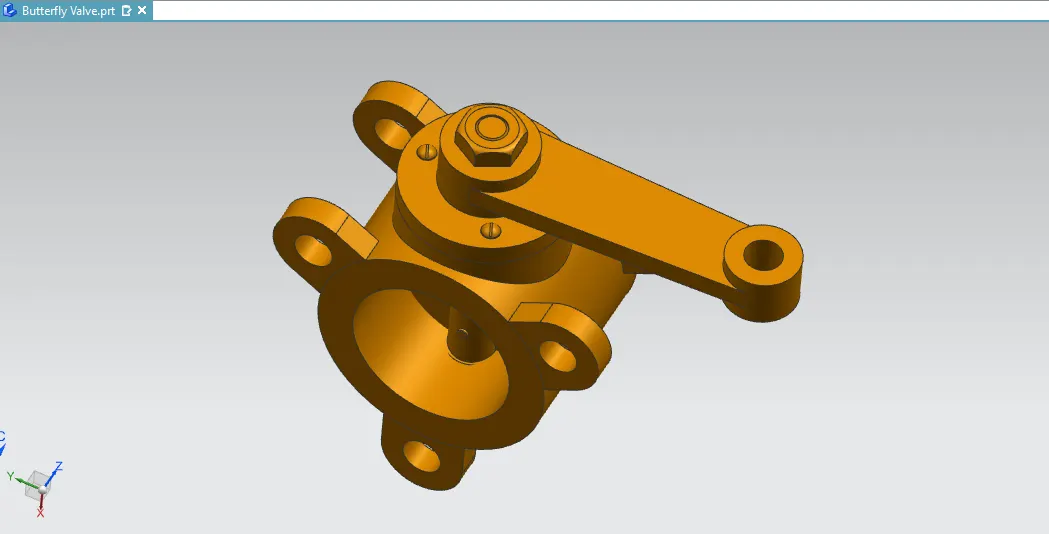
Then select the assembly command pick on axis option to create the axis part after that the select the touch option to pick on to parts in what ever part to assemble. Finally the butterfly valve assembly would be created.
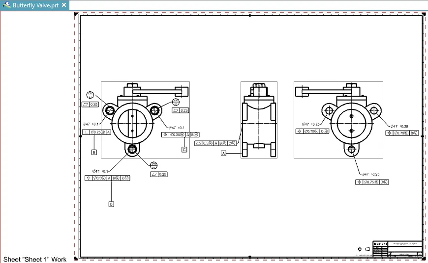
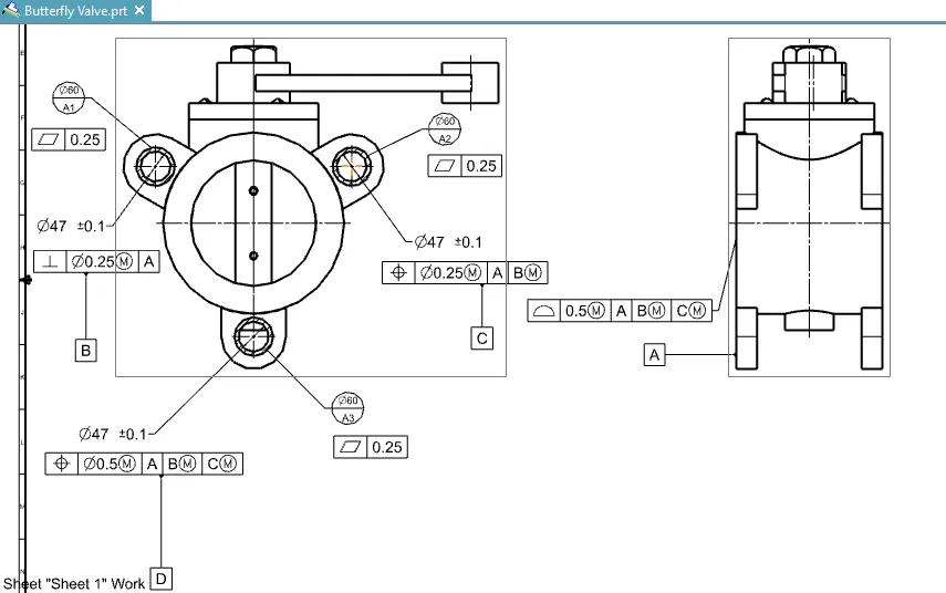
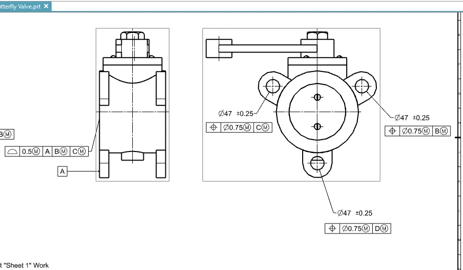
And create the Draft on butterfly valve assembly and apply the GD&T in feature control frame .The form of feature control frame is (Position, Perpendicular, Profile on surface, Flatness)with Datum target and datum's.
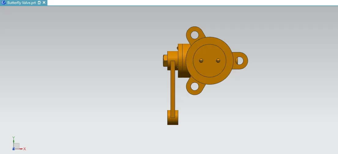
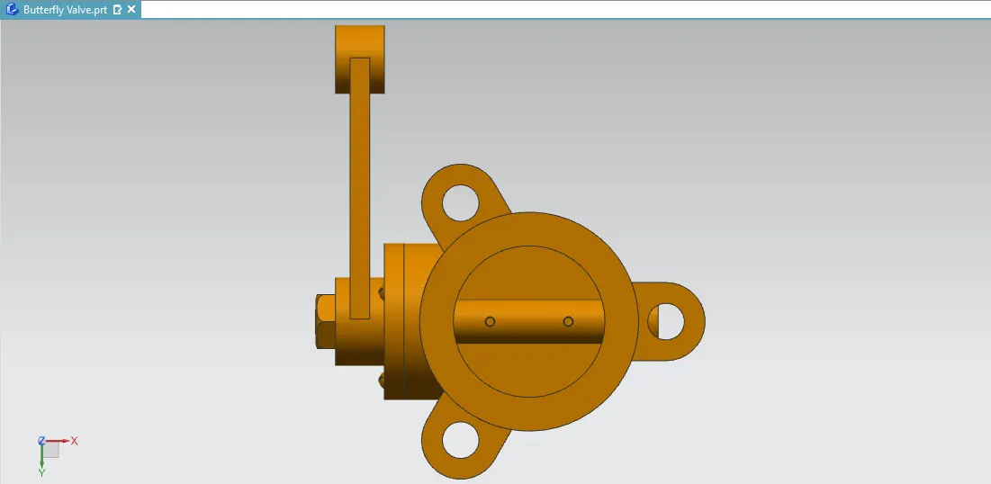
TOP VIEW
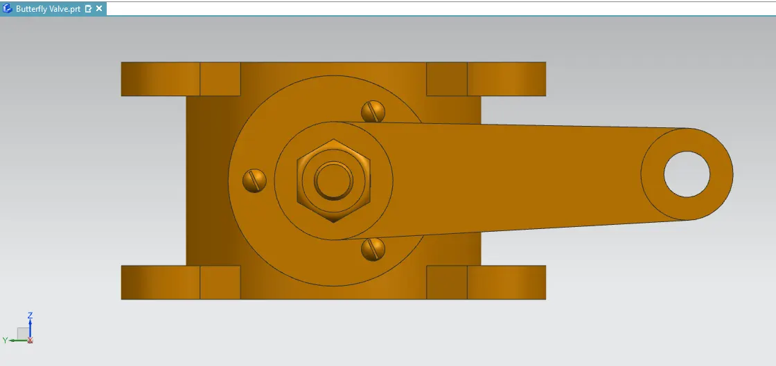
BOTTOM VIEW:
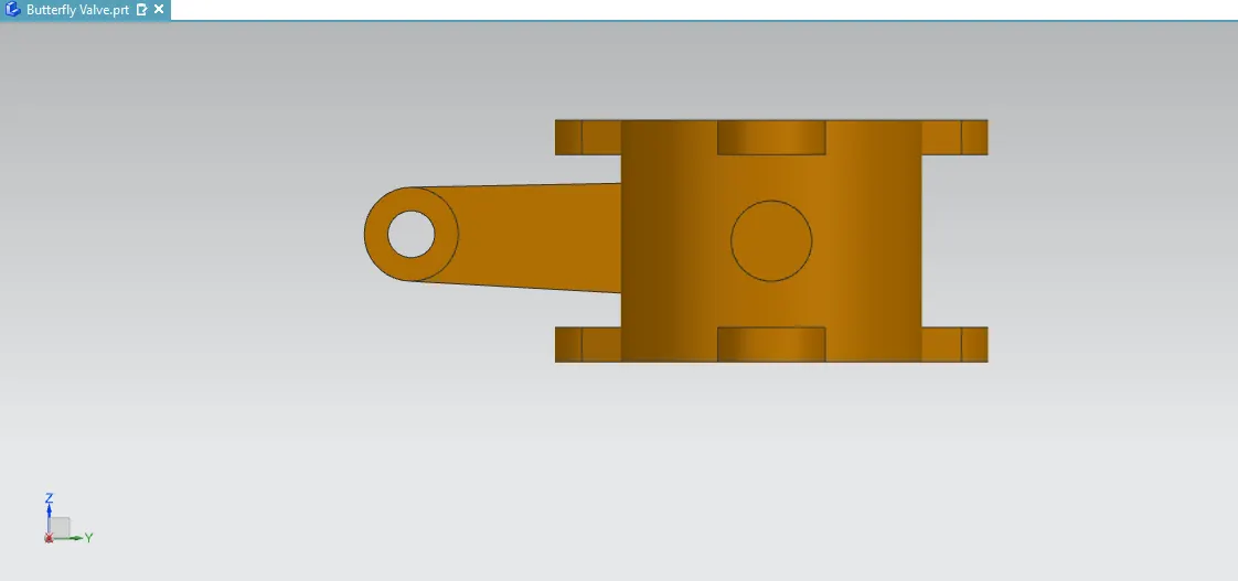
SIDE VIEW:
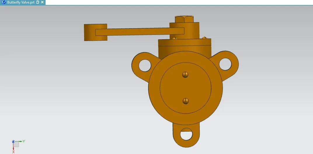
ISO METRIC VIEW:
DRAFT & GD&T: