Week 14 challenge
OBJECTIVE : The objective of this project is to design a butterfly valve and apply GD&T to it's components and final assembly using CATIA V5 .
INTRODUCTION:
A butterfly valve is from a family of valves called quarter-turn valves. In operation, the valve is fully open or closed when the disc is rotated a quarter turn. The "butterfly" is a metal disc mounted on a shaft. When the valve is closed, the disc is turned so that it completely blocks off the passageway. When the valve is fully open, the disc is rotated a quarter turn so that it allows an almost unrestricted passage of the fluid. The valve may also be opened incrementally to throttle flow. There are different kinds of butterfly valves, each adapted for different pressures and different usage.
Why GD &T is helpful-
- Saving Money - GD&T enhances design accuracy by allowing for appropriate tolerances that maximize production. For many projects, the process provides extra or bonus tolerances, further increasing cost effectiveness.
- Offering Uniformity and Convenience - As a single, consistent language, GD&T reduces guesswork and interpretation while ensuring consistent geometries across design and manufacturing.
- Assisting Digital Design Methods — Clear, concise GD&T data is readily adaptable to digital design programs, including nearly universally used 2D and 3D CAD files.
- Ensuring Dimensional and Tolerance Requirements — By explicitly stating all design requirements, a thorough GD&T process guarantees accurate fulfillment of all dimensional and tolerance specifications.
- Providing Accurate Communication — Today’s intricate designs demand the most accurate and reliable communication. GD&T enables designers, manufacturers, and inspectors to communicate clearly with one other, saving time and making the process more efficient.
Alignment and fixation of product -
A work-piece free in space can move in an infinite number of directions. For analysis, this motion can be broken down into 12 directional movements or "degrees of freedom". All 12 degrees of freedom must be restricted to ensure proper referencing of a work-piece.
COMPONENTS OF BUTTERFLY VALVE-
- BODY
- Shaft
- Disc
- LEVER
- Retainer
- NUT
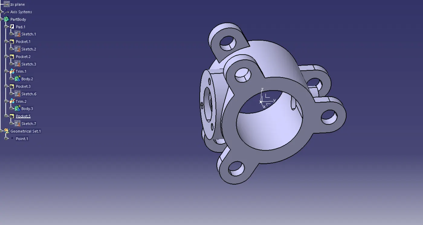
1) BODY - BUTTERFLY VALVE:
Butterfly valves are usually fixed between two pipleines using flange couplings.
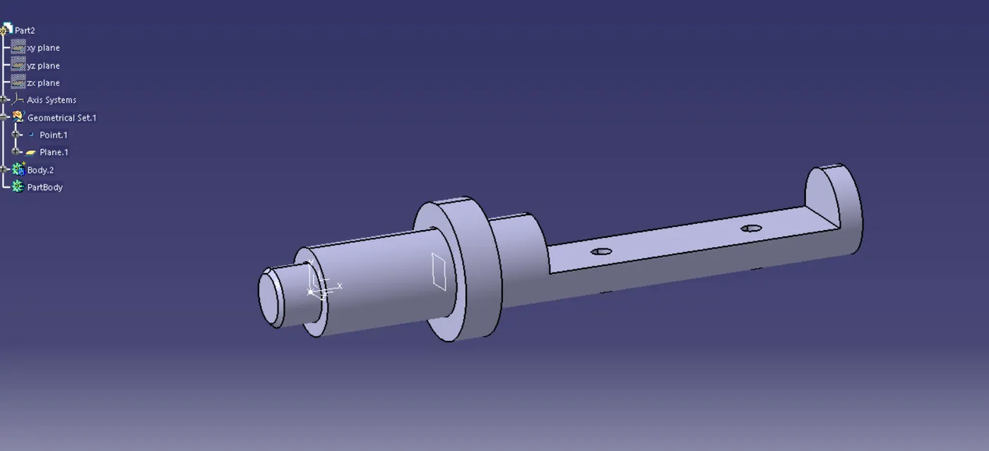
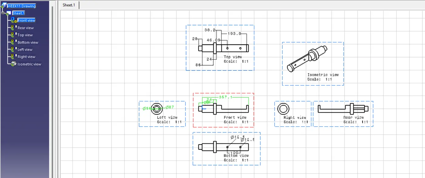
2) SHAFT - BUTTERFLY VALVE:
The disc/plate, lever and nut are assembled to this shaft. Drafting is done for this part
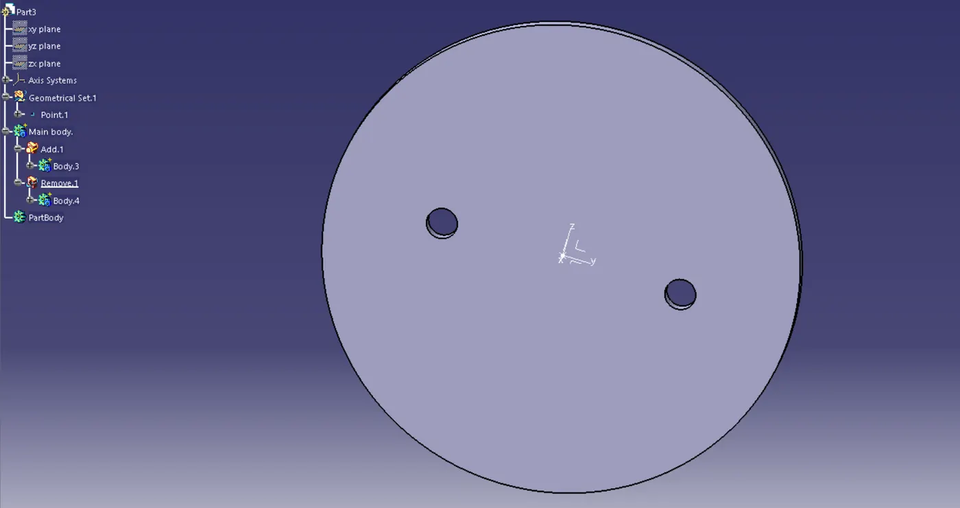
3) DISC - BUTTERFLY VALVE:
When valve is fully opened or closed the disc is rotated a quarter turn. Disc is mounted on shaft. When the valve is closed, the disc is turned so that it completely blocks off the passageway. When the valve is fully open, the disc is rotated a quarter turn so that it allows an almost unrestricted passage of the fluid
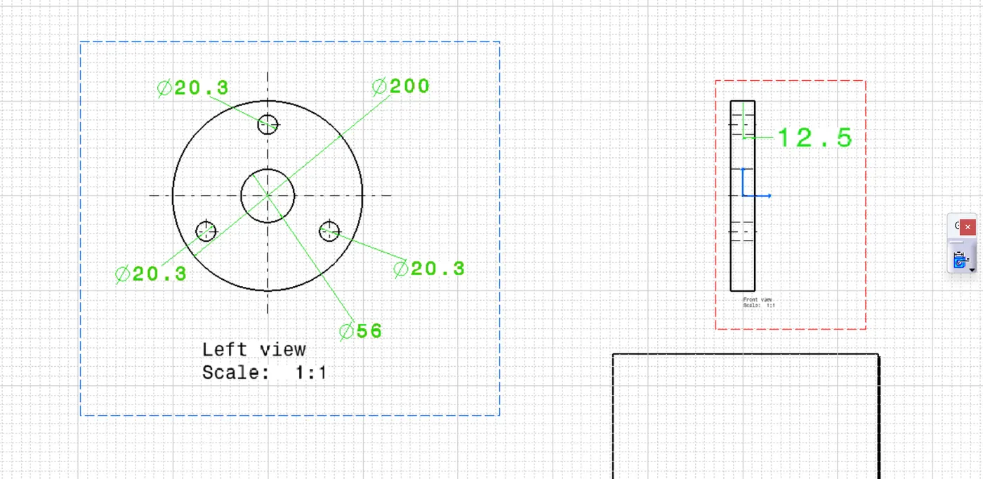
4) LEVER - BUTTERFLY VALVE:
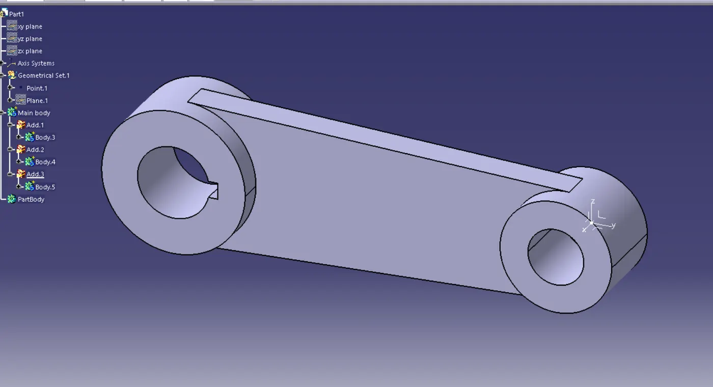
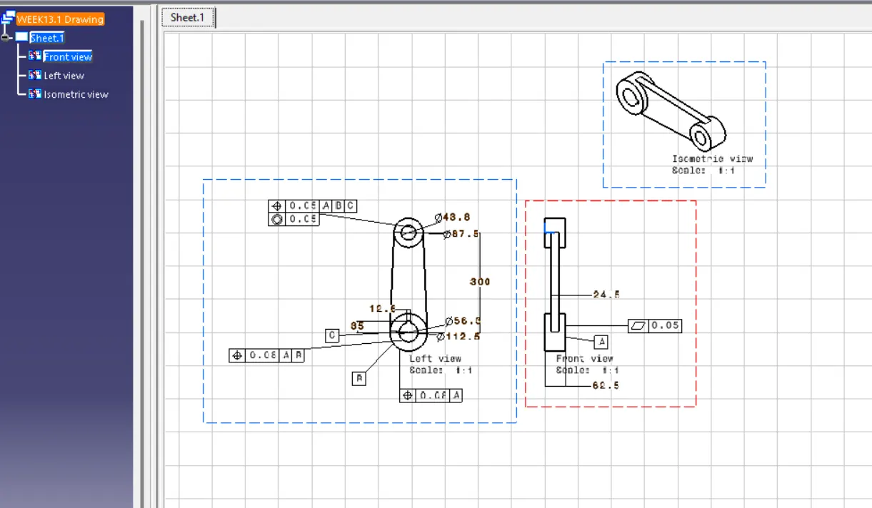
Lever is mounted at an end of shaft outside the body. Hand lever is usually used in small sized Butterfly valves. It is used to open or close the valve.
5) RETAINER - BUTTERFLY VALVE
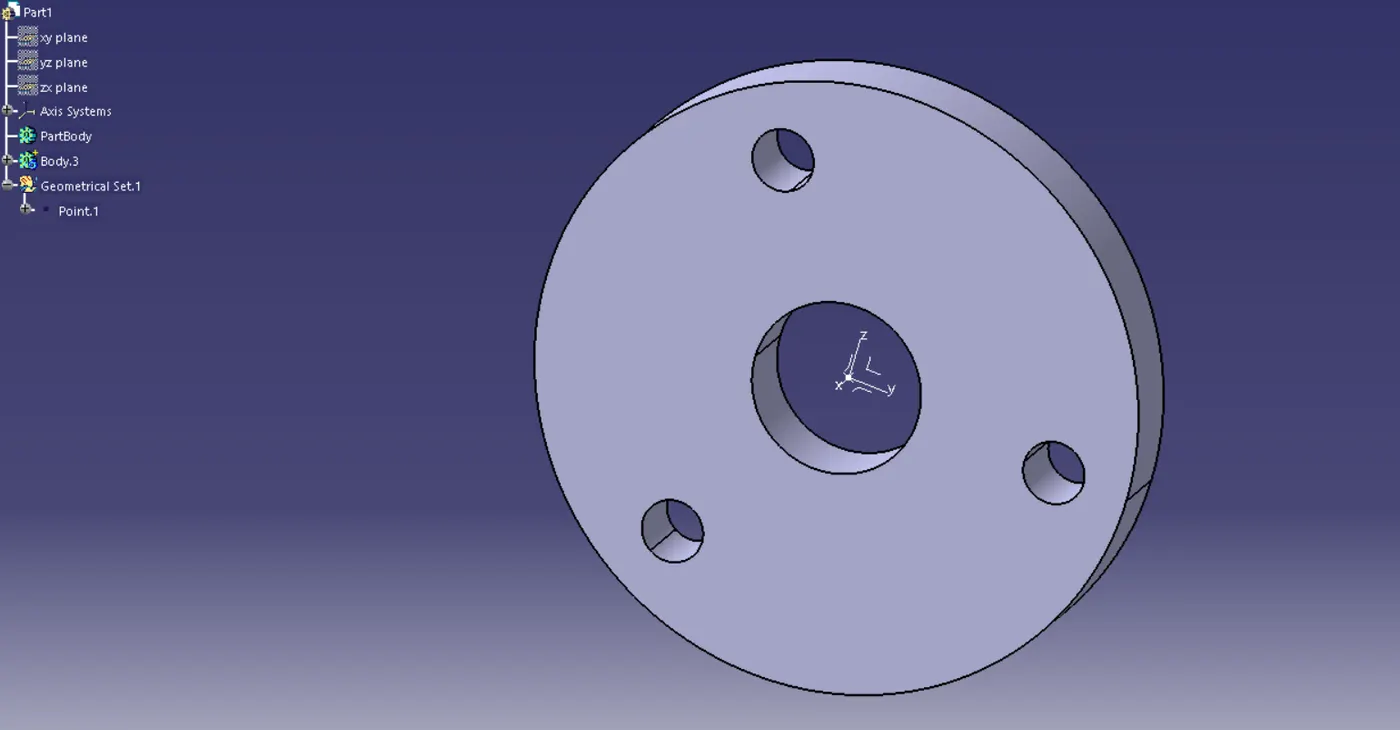
Retainer is a kind of washer fixed on the body of butterfly valve.
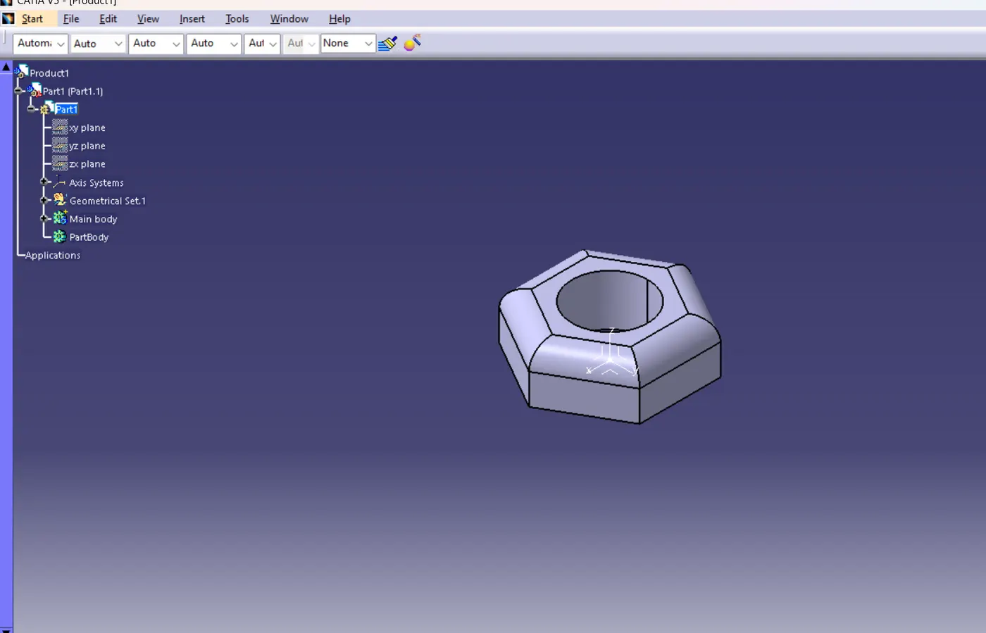
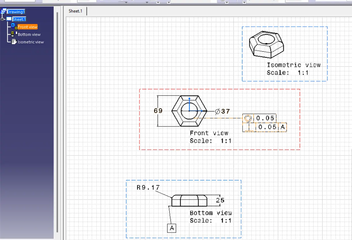
6) NUT - BUTTERFLY VALVE:
It is fixed at the top end of shaft to keep the lever and retainer on position relative to the body of butterfly valve.
ASSEMBLY - BUTTERFLY VALVE:
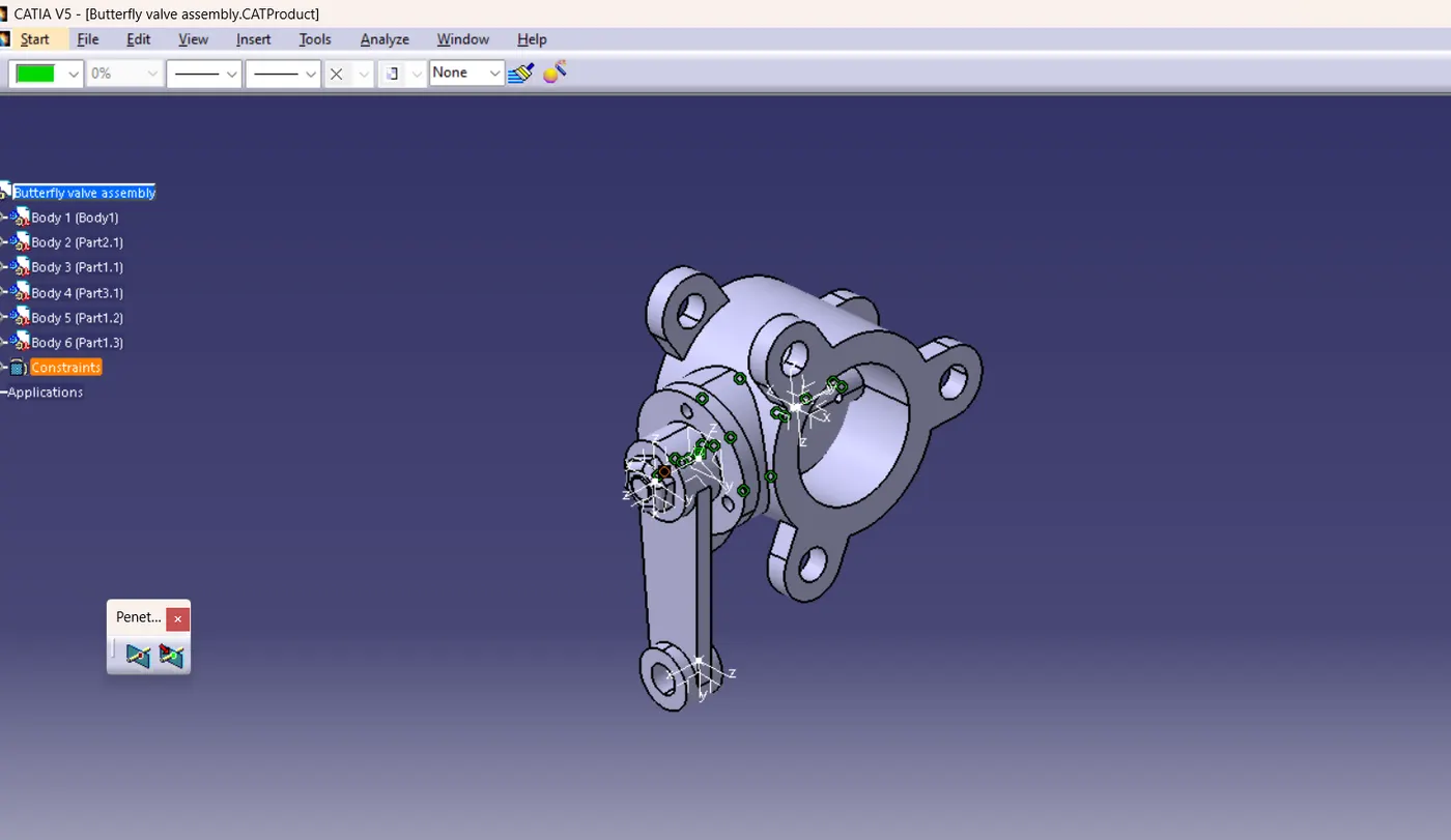
After completing the modelling of all components of butterfly valve, all parts were assembled together using CATIA V5 Assembly workbench.
& by using constraints ,manipulate & snap features prepare assembly of the butterfly valve
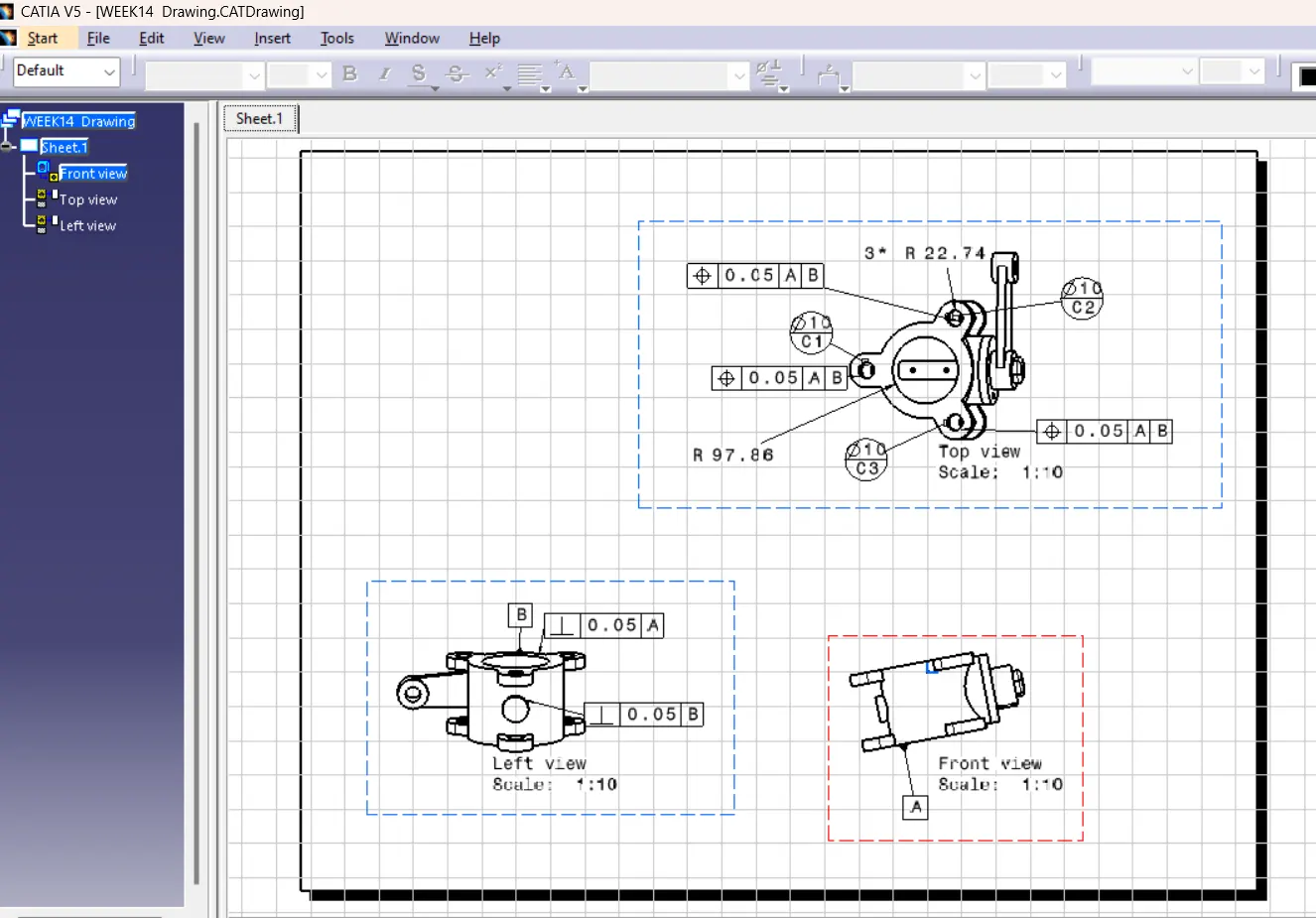
Then go to drafting & prepare drawing for this assembly & gd &T Parameters as well as datum
CONCLUSION :
Butterfly valve was successfully designed and GD&T applied to all parts and the assembly of the Butterfly valve.