Week 14 challenge
AIM:
To Assemble all the Parts of Butterfly Valve in assembly workbench. And Implement the GD&T fundamental and Denote it on Drawing Sheet for the assembly.
COMPONENTS OF BUTTERFLY VALVE ASSEMBLY:
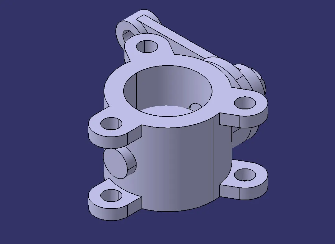
- Body of Butterfly Valve
- Shaft
- Retainer
- Disc plate
- Lever
- Nut
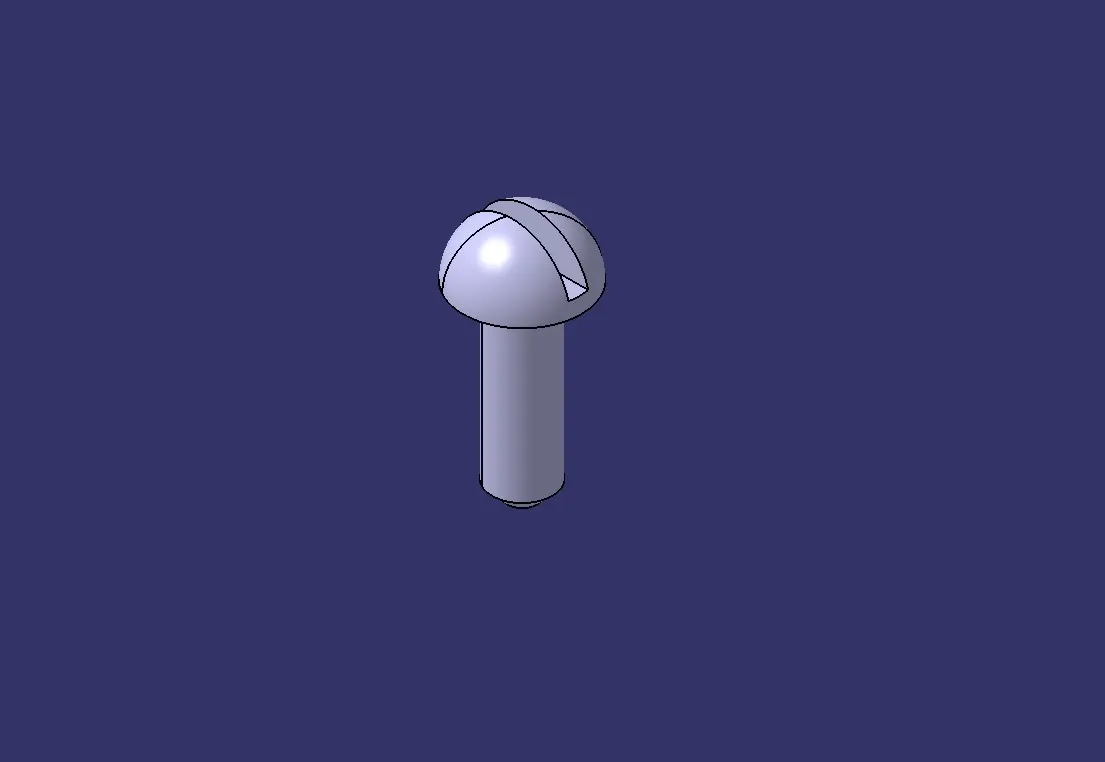
- Screw
INTRODUCTION:
- A butterfly valve is a type of valve used to control the flow of a fluid through a pipe or duct. It consists of a circular disc or plate that rotates within the pipe to either allow or block the flow of the fluid. The disc is mounted on a shaft, which is connected to an actuator that controls the rotation of the disc.
- When the disc is turned parallel to the direction of flow, it allows fluid to pass through, similar to how opening a door allows passage through a doorway. Conversely, when the disc is rotated perpendicular to the flow direction, it blocks the flow, similar to closing a door.
- Butterfly valves are often used because they are lightweight, compact, and relatively easy to operate. They can be quickly opened or closed, making them suitable for applications where rapid flow control is needed. Additionally, they provide good flow control capabilities with minimal pressure drop across the valve when fully open.
- Butterfly valves are used in various industries, including water treatment, HVAC (heating, ventilation, and air conditioning), power generation, chemical processing, and oil and gas production. They are particularly useful for large-diameter pipes and applications requiring frequent operation or throttling of flow.
1.BODY OF BUTTERFLY VALVE:
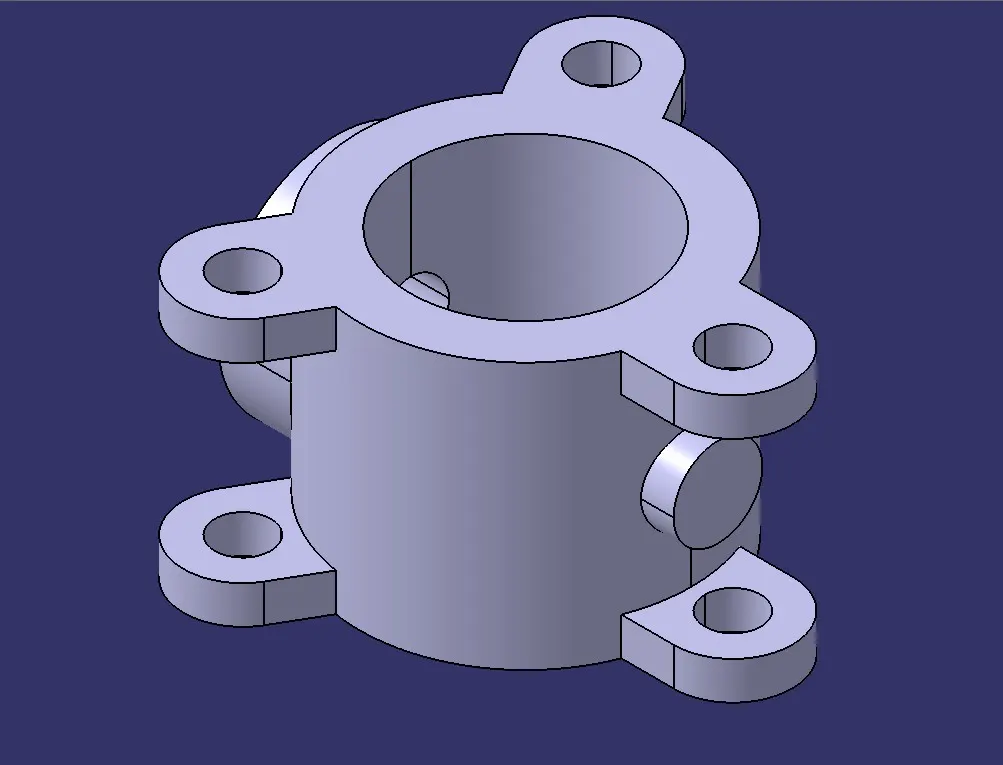
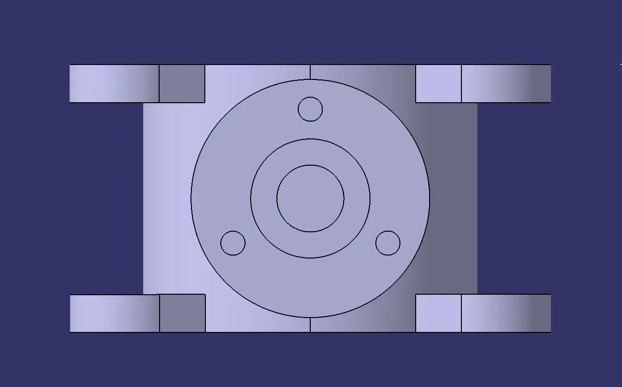
The body is the housing for the internal components and it is the main part of the butterfly valve.The body connects to two pipes on its two sides and it regulates to flow.
For create that body Initially, the sketch for the body of the butterfly valve is drawn using the circle tool in NX software.
After extruding the sketch which is drawn,the ears of the Butterfly valve is drawn and then it is copied on both sides of the cylindrical portion.
Now, the datum plane option is used to create cylindrical portion and the counter bore option is used to provide a counter bore to the part with the specified dimensions.
Image mention below.
2. SHAFT:
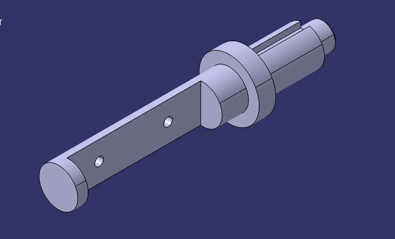
Shaft is the another important component of the butterfly valve. It inserts into the body of the valve and sits perpendicular to the direction of flow.It holds the disc inside the body and is clamped with the lever outside the body.
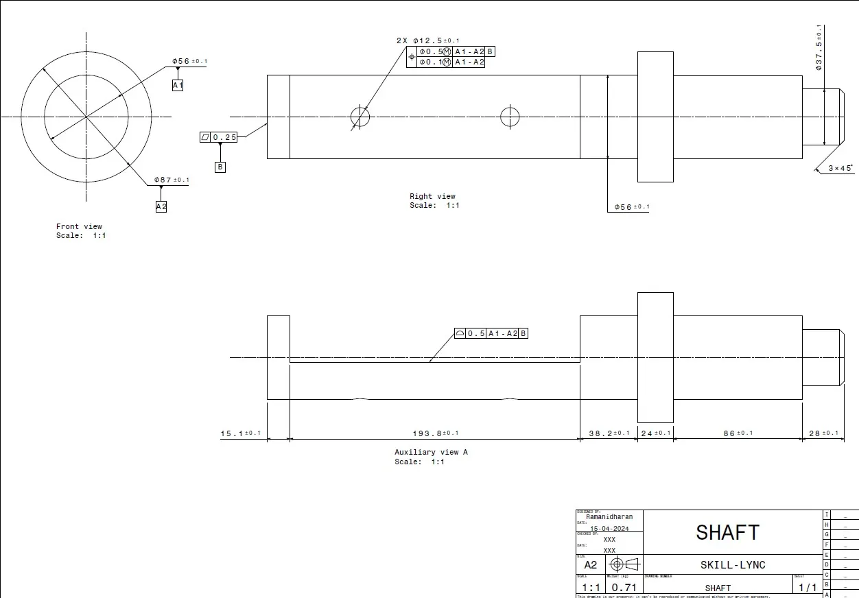
The 2D drawing given in the figure is used to convert the Sketch into 3D model with different operations. The revolve option is used to create the shaft by rotating it through 360°. Now the extrude option(Subtract) is used to provide the recess in the front and rear portion of the shaft. Finally,the two holes of 12.5mm diameter is provided in the rear recess portion of the shaft.
Image mention below.
GD&T AND DRAFTING OF THE SHAFT:
3. RETAINER:
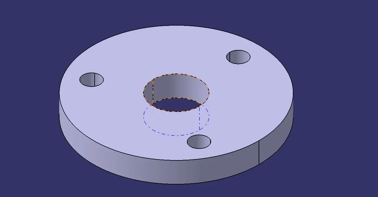
Retainer helps to retain or to fix the shaft with the body of the butterfly valve.It prevents the shaft from coming out of the body and keeps it in position for the proper functioning of the disc inside the body.
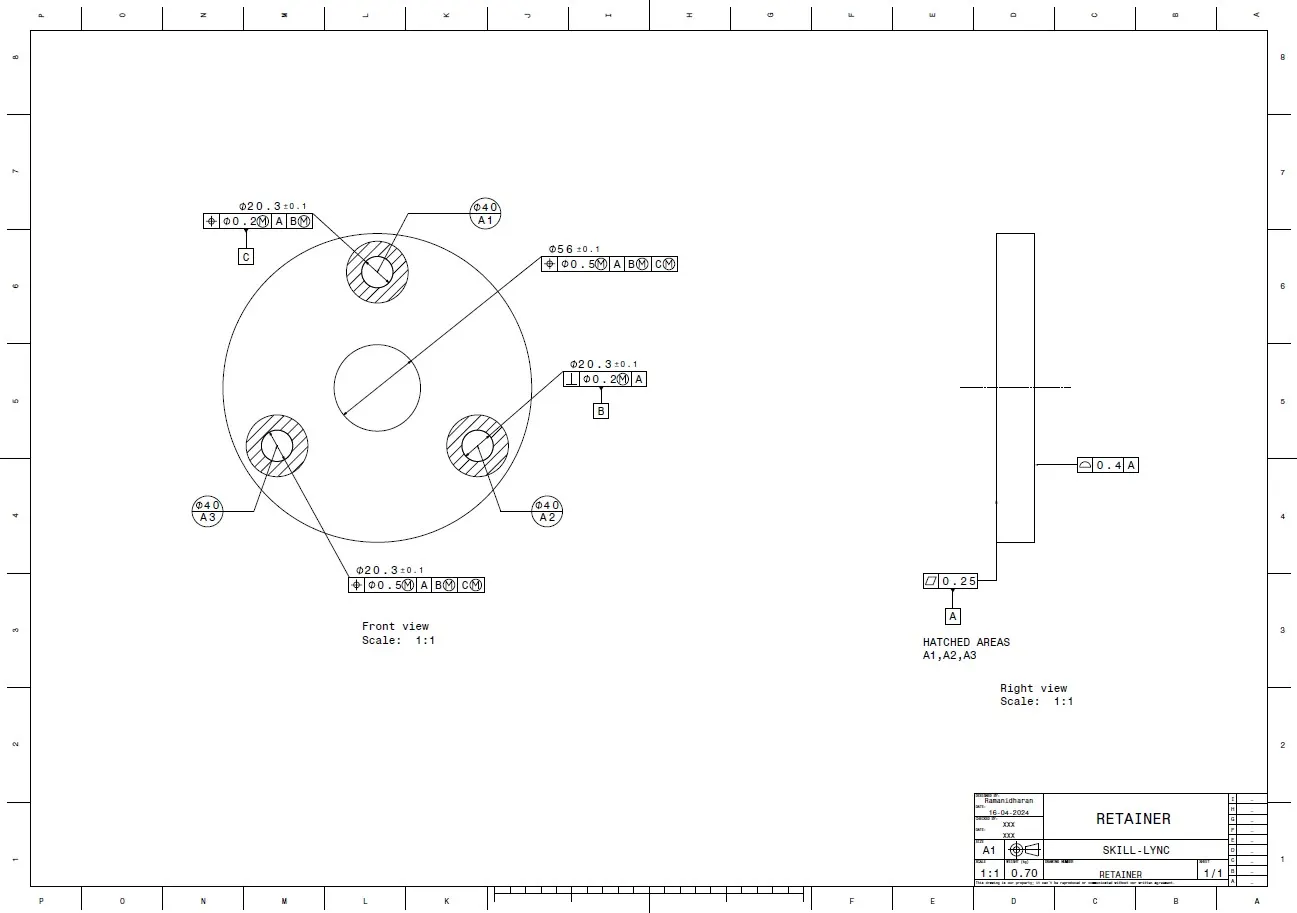
Initially,the concentric holes of 200mm and 56mm diameter are drawn and the other 3 circles of 20.3 mm diameter is drawn with the help of 150mmBCD by using Pattern option.
Image mention below.
GD&T AND DRAFTING OF THE RETAINER:
4. DISC PLATE:
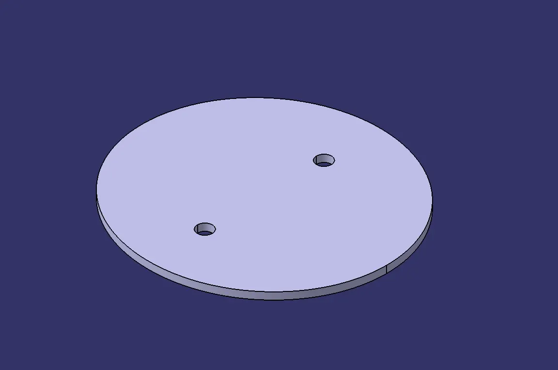
This disc plate is the main component of the butterfly valve which regulates the flow in the valve.The orientation of this disc determines the flow rate of the fluid. It is not perfectly circular, rather it is elliptical in profile.
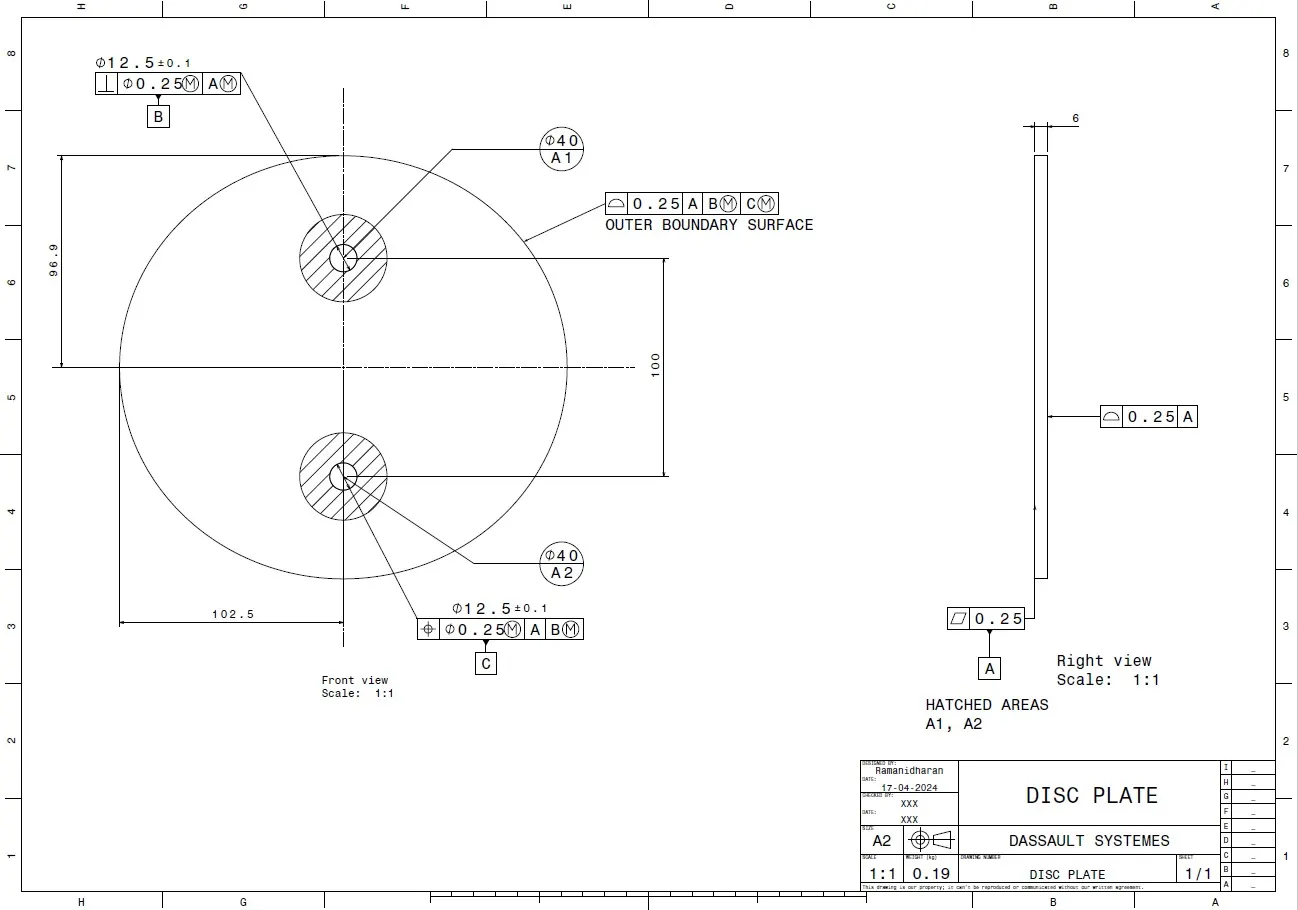
Initailly,with the help of 2D drawing the disc plate is designed. The ellipse with a minor and major radius is created and then the two holes of 12.5 diameter is given.
Image mention below.
GD&T AND DRAFTING OF THE DISC PLATE:
5.LEVER:
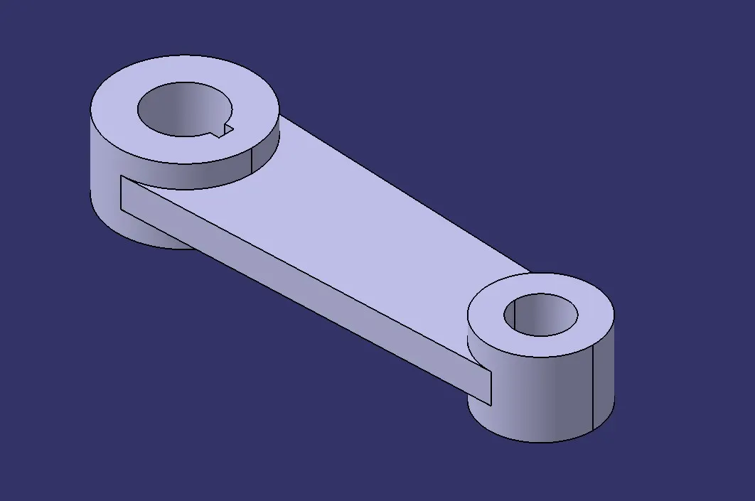
A lever is a handle that is used to rotate in order to regulate the flow. It is attached to the shaft with the help of a key to fixing it in position with respect to it.So when it is rotated, the shaft rotates which in turn rotates the disc and regulates the flow inside the pipe.
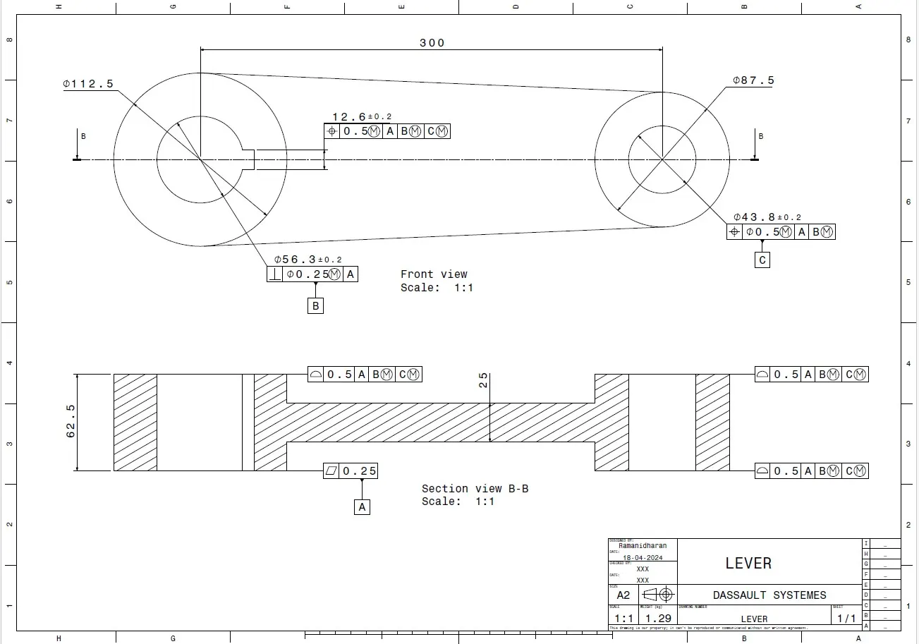
With the help of 2D drawing of the lever,the 3D model of the lever is designed with the help of different operations. The different operations used are Trim,Extrude,circle,Tangency etc.
Image mention below.
GD&T AND DRAFTING OF THE LEVER:
6. NUT:
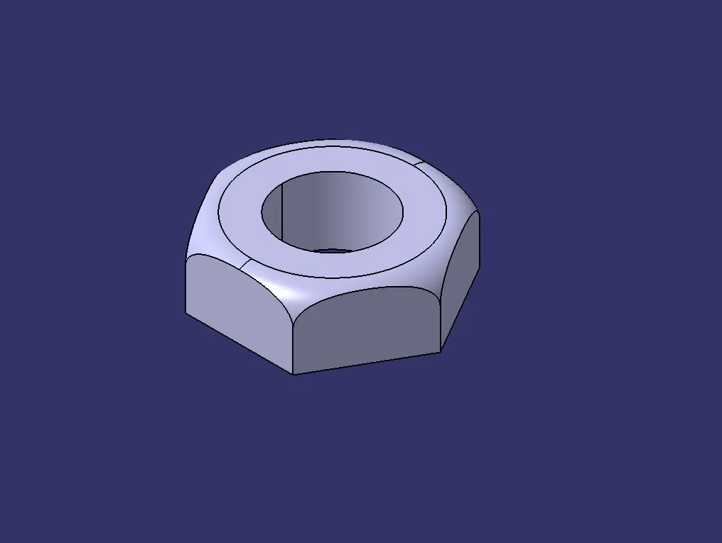
It is the last part that helps to fix the lever in position with the stem.It allows to keep it in position or to disassemble whenever required.
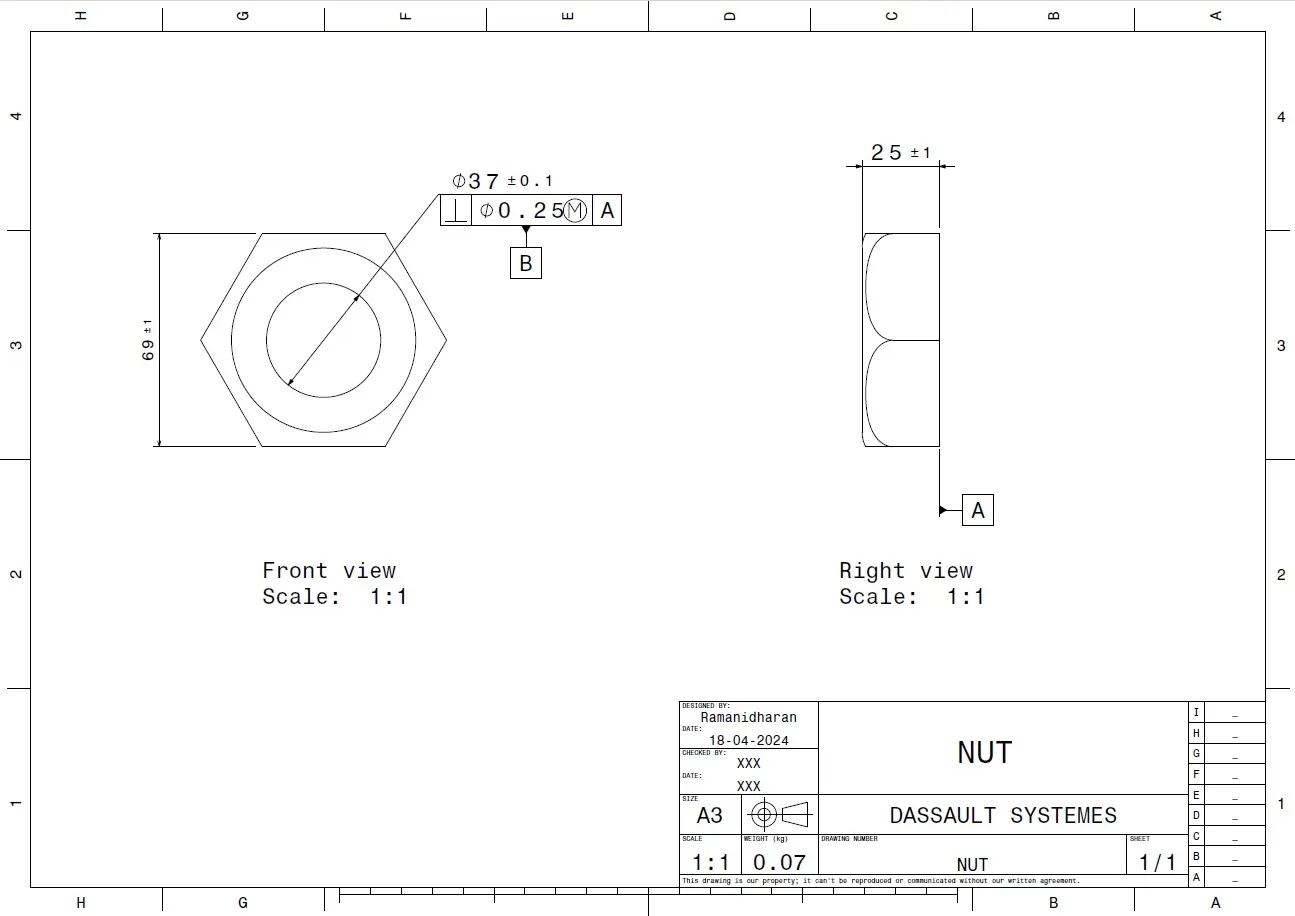
The 3D modeling of the Nut is created with the given dimensions. Initially the hexagonal shaped nut is extruded with a depth of 25mm and a hole of 37mm diameter. the fillet of radius was 10mm.
Image mention below.
GD&T AND DRAFTING OF THE NUT:
7. SCREW:
This Screw helps to retain or to fix the Disc with the Shaft of the butterfly valve. It prevents the shaft from coming out of the body and keeps it in position for the proper functioning of the disc inside the body.
Image mention below.
FINAL ASSEMBLY OF BUTTERFLY VALVE:
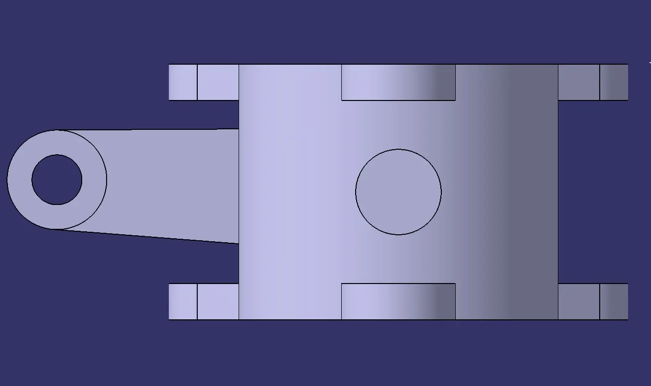
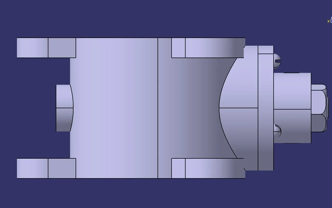
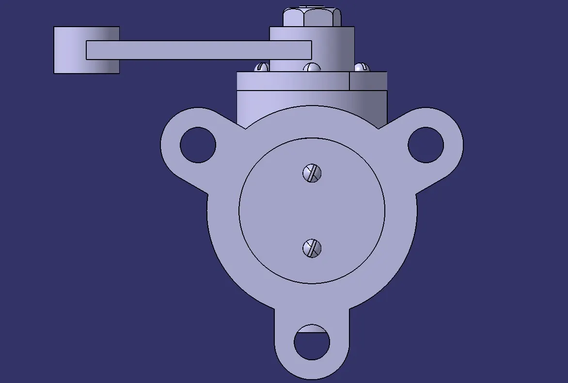
- The assembly is created by first adding all the sub parts in assembly workbench.
- Then the shaft and disc are joined together.
- Then that shaft disc assembly is then assembled to the body.
- Then retainer plate is assembled with the body.
- Then the lever is assembled to the shaft in a position that is then fixed.
- Then the nut is assembled with the shaft.
- Then assemble the screw also.
Image mention below.
FRONT VIEW:
SIDE VIEW:
TOP VIEW:
ISOMETRIC VIEW:
GD&T AND DRAFTING OF THE ASSEMBLY:
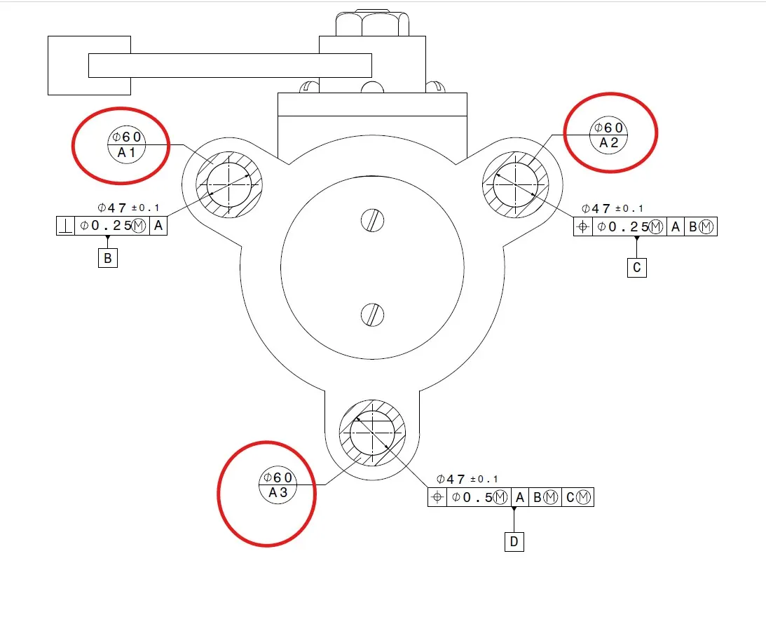
Above image i marked the datum target A1, A2, A3 in the diameter of 60. Around the surface of the hole.
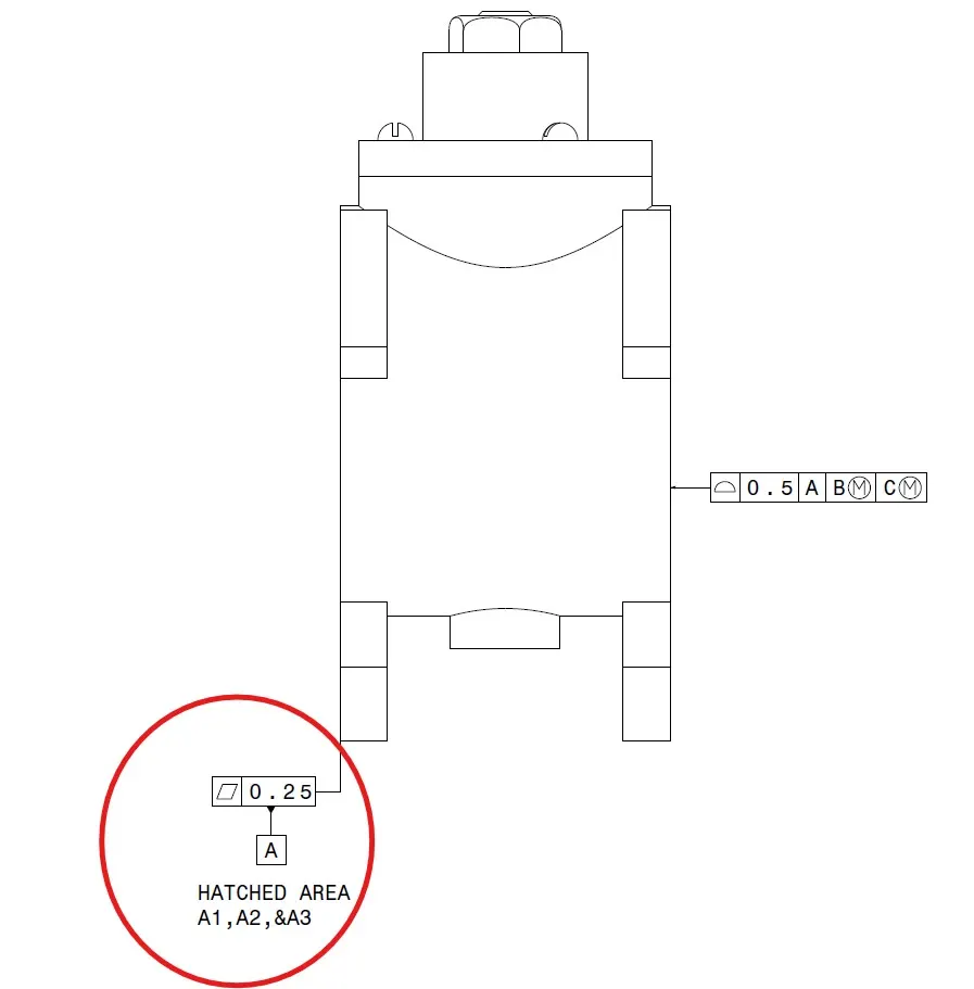
Above shows that the in the front view i marked the datum target A1, A2, A3 for that surface i mention in the side the flatness tolerance of 0.25mm and marked as a datum A. because it is the mating surface.
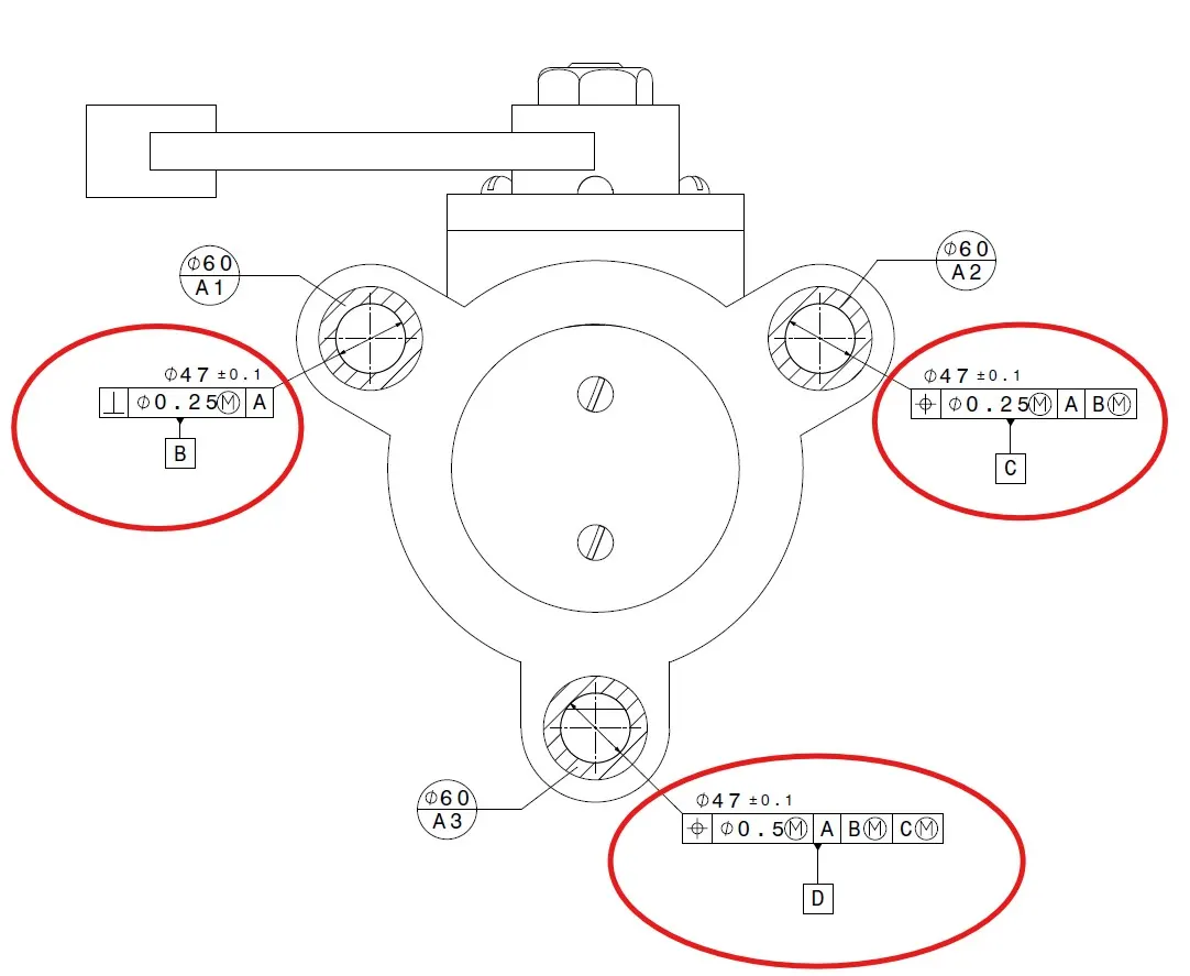
Above image i mention the tolerance for hole for one hole i give the perpendicularity tolerance of 0.25mm at maximum material condition with respect to datum A. and mention as datum B.
For second hole i give position tolerance of 0.25mm at maximum material condition with respect to datum A and datum B at maximum material condition. mention as datum C.
For third hole i give position tolerance of 0.5mm at maximum material condition with respect to primary datum A and secondary datum B at maximum material condition and teritary datum C at maximum material condition. mention as datum D.
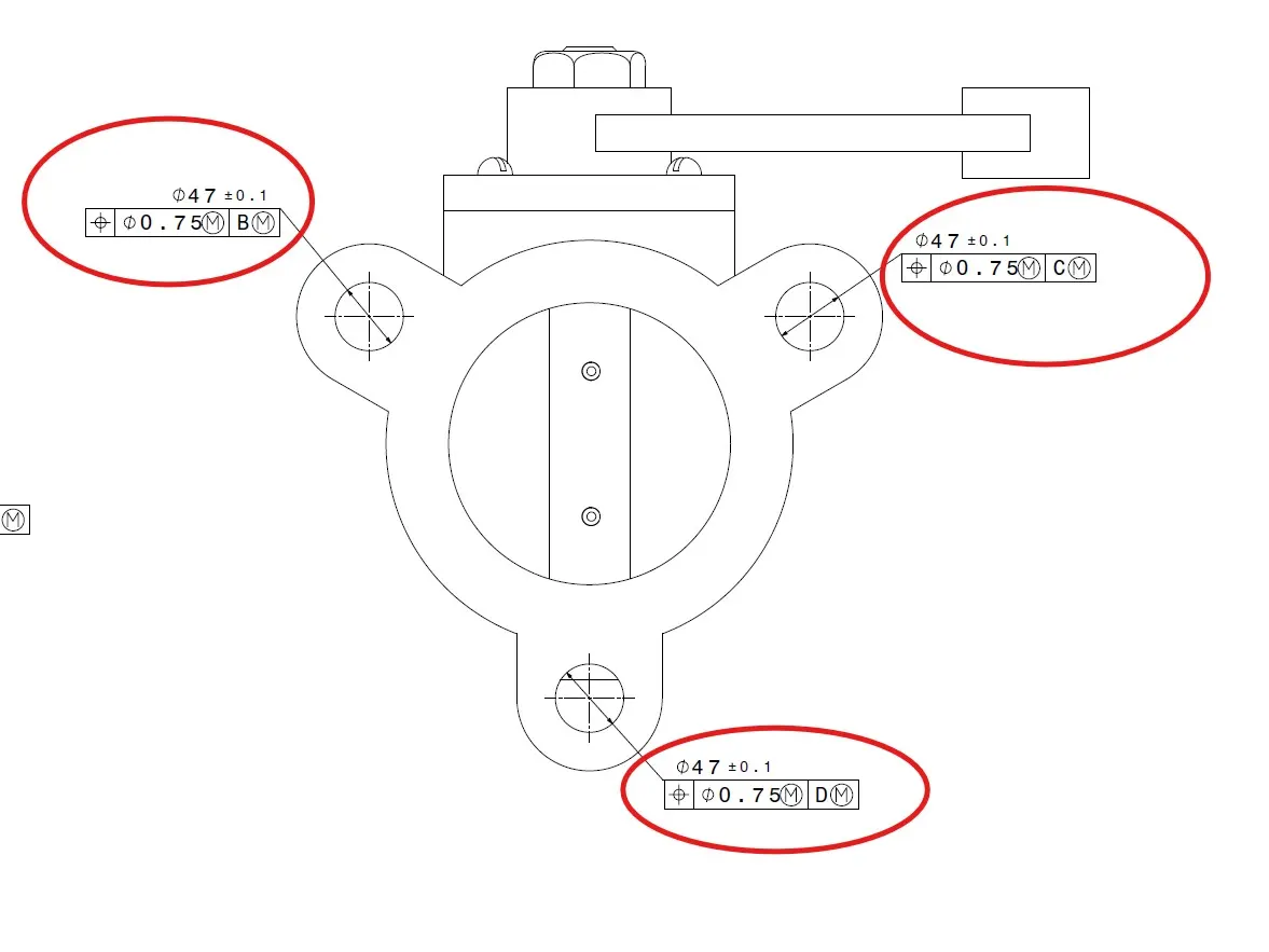
Above image i mention the tolerance for hole for one hole i give the position tolerance of 0.75mm at maximum material condition with respect to datum B at maximum material condition. because it is other side of the surface which contains the holes so, we give the position tolerance with respect to the datum B.
For second hole i give the position tolerance of 0.75mm at maximum material condition with respect to datum C at maximum material condition.
For third hole i give the position tolerance of 0.75mm at maximum material condition with respect to datum D at maximum material condition.
It make the component mate perfectly with the other components.
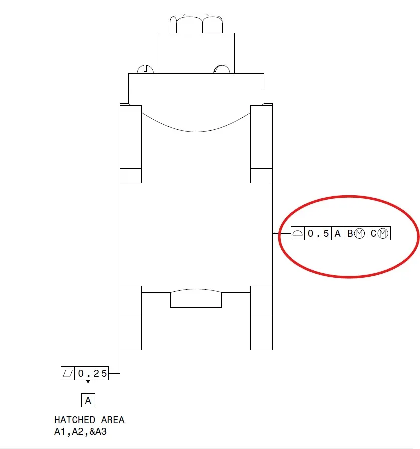
Above image i marke the profile of surface tolerance must lies within the 0.5mm with respect to primary datum A and secondary datum B at maximum material condition and teritary datum C at maximum material condition. because we give the front surface as flatness so, we give profile of surface to the back surface with respect to the front surface.
CONCLUSION:
We Assemble all the components Of Butterfly Valve in assembly workbench.and Implement the GD&T fundamental and Denote it on Drawing Sheet for the assembly.