Week 14 challenge
AIM:- The aim of this project is to model a butterfly valve and to apply GD&T to the different parts of the butterfly valve and the assembly.
Parts of Butterfly Valve :-
- Body of Butterfly Valve
- Shaft
- Retainer
- Disc
- Lever
- Nut
- Screw
- Final Assembly
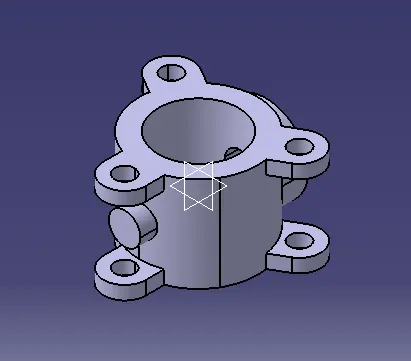
1.BODY OF BUTTERFLY VALVE:-
- 1.Initially, the sketch for the body of the butterfly valve is drawn using the circle tool in CATIA.
- 2.After extruding the sketch which is drawn,the ears of the Butterfly valve is drawn and then it is copied on both sides of the cyclindrical portion.
- 3.Now, the datum plane option is used to create cyclidrical portion and the counter bore option is used to provide a counter bore to the part with the specified dimensions.
- 4.Finally, the hole is provided for the mounting of the body and it is saved in the required folder
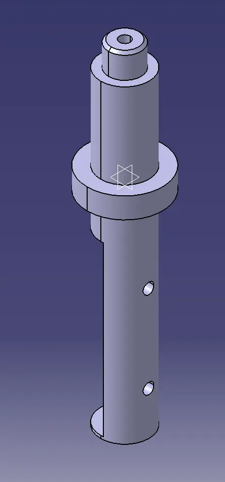
2.SHAFT:-
- 1.The 2D drawing given in the figure is used to convert the Sketch into 3D model with different operations.
- 2.The revolve option is used to create the shaft by rotating it through 360°.
- 3.Now the extrude option(Subtract) is used to provide the recess in the front and rear portion of the shaft.
- 4.Finally,the two holes of 12.5mm diameter is provided in the rear recess portion of the shaft and the part is saved in the required folder.
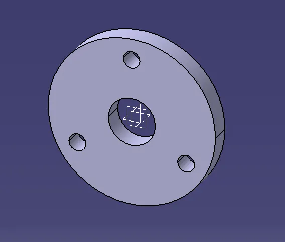
3.RETAINER:-
- 1.The 3D model of the Retainer is created with the help of given dimensions.
- 2.Initially,the concentric holes of 200mm and 56mm diameter are drawn and the other 3 circles of 20.3 mm diameter is drawn with the help of 150mmBCD by using Pattern option.
Finally, the 2D sketch is extruded and the part is saved in the required folder.
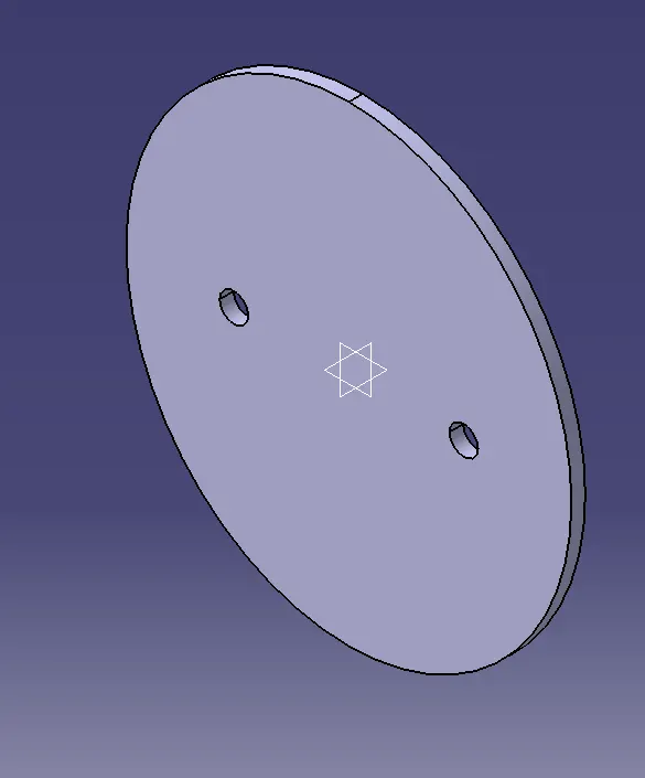
4.DISC PLATE:-
- 1.Initailly,with the help of 2D drawing the disc plate is designed.
- 2.The ellipse with a minor and major radius is created and then the two holes of 12.5 diameter is given.
- 3.Finally, the sketch is extruded and the part is saved in the required folder.
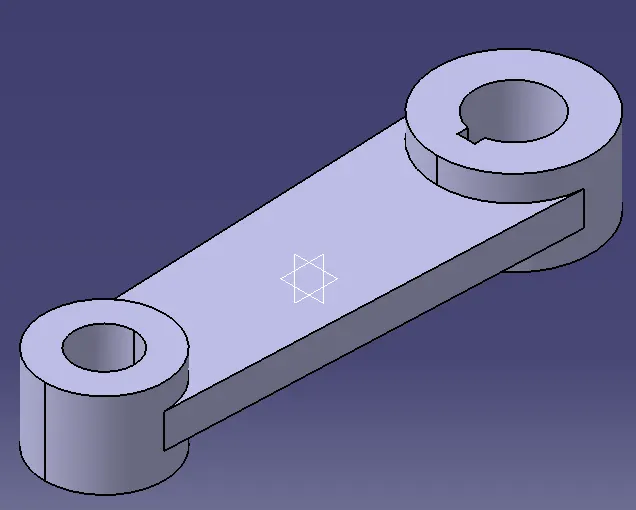
5.Handel:-
- 1.With the help of 2D drawing of the lever,the 3D model of the lever is designed with the help of different operations.
- 2.The different operations used are Trim,Extrude,circle,Tangency etc.
- 3.Finally,the part is saved in the required folder.
6.NUT:-
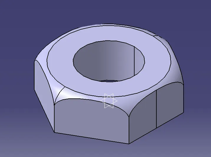
- 1.The 3D modeling of the Nut is created with the given dimensions.
- 2.Initially the hexagonal shaped nut is extruded with a depth of 25mm and a hole of 37mm diameter.
- 3.Finally, the fillet of radius 10mm is provided by using the revolve option.
8.ASSEMBLY OF BUTTERFLY VALVE:-
- 1.All the parts that are saved in the required folder is opened in the Add components tool box.
- 2.Now using the Move option and Assembly Constraints option the different parts are joined together with the help of Align,touch,infer/Axis operations.
- 3. Finally,the assembly of butterfly valve is saved in the folder where the other parts were saved.
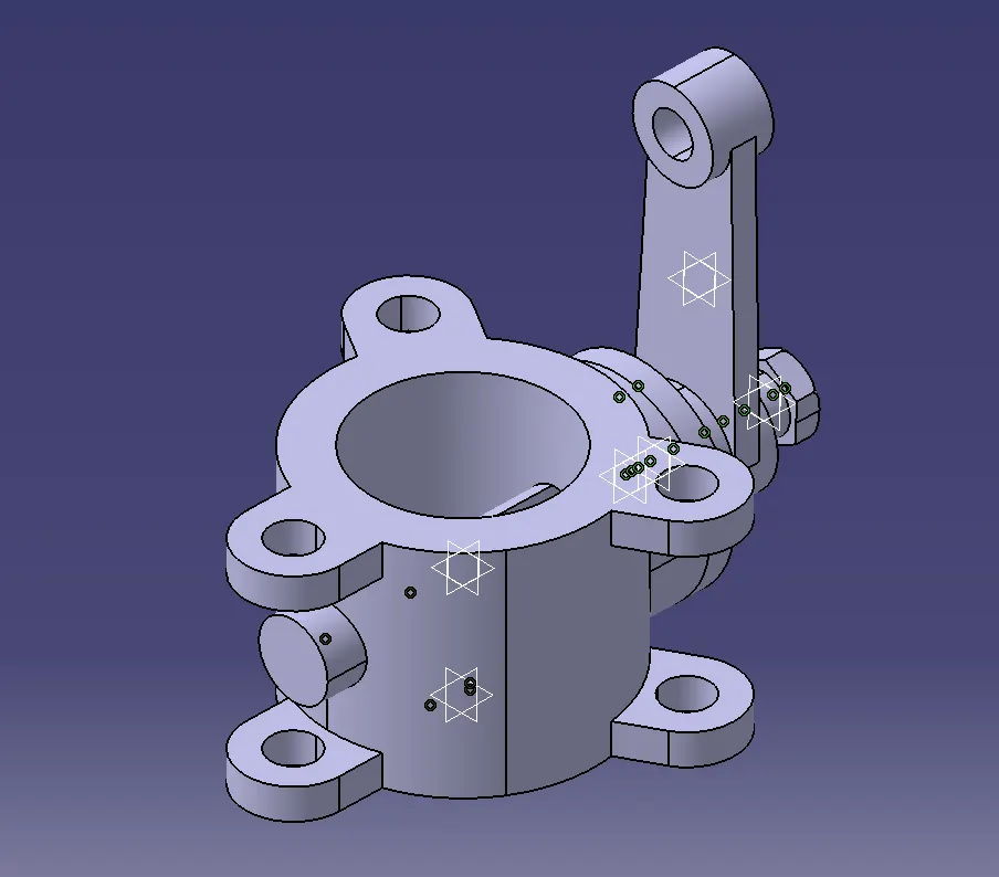 CONCLUSION: Therefore,the Butterfly valve is created and the Geometric Dimensioning and tolerances are applied with the help of using CATIA software.