Week 14 challenge
OBJECTIVE:
In this Project, we combine all the component files of the Butterfly valve into an assembly and also apply GD& T symbols to the assembly drawing.
PROCEDURE:
We begin the process by starting a new assembly file on NX CAD.
Once created, we move on to importing all the components of the assembly namely:
- Main Body
- Disc
- Retainer
- Lever
- Nut
- Shaft
- Screws
For compatibility, we fix the main body to the absolute coordinate system.
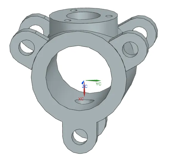
Now, we have to constrain each component with its respective functional counterpart.
First, we go for the shaft and disc. We bring the disc as close to the shaft using the move command and use dynamic positioning to adjust its position and orientation.
Then we constrain the axis of the holes of the disc and shaft using infer center/axis orientation. We use the command for both holes. And then we use the touch orientation to completely constrain the disc and shaft. We also center align the screws with the holes on the shaft and touch the command to perfectly align the screws.
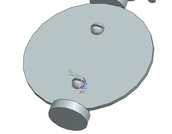
Now the proper constraints have been provided for the shaft disc combination, we will proceed to constrain the shaft axis with the main body hole axis. We also provide a touch constraint such that the outer disc surface touches the main body's inner hole surface.
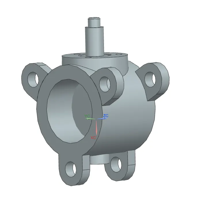
Later on, we align the center axis of the retainer and shaft with touch constrain assigned to the bottom surface of the retainer and the top surface of the main body. To that, we also attach and align the Lever along with the nut and screws.
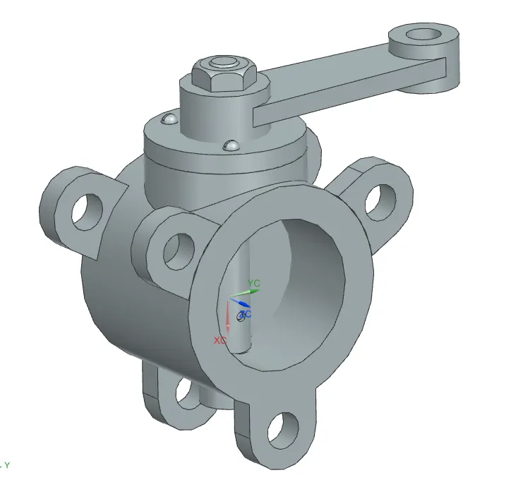
Once the Assembly of the Butterfly valve is completed, we proceed to the drafting Application for assigning proper GD& T symbols.
For the A datum, we select any one of the two planar surfaces with ears by specifying a datum target area of 60mm diameter around the holes. A1, A2, A3 together form the A datum. To each of the datum target areas, we also assign a flatness tolerance of 0.25mm.
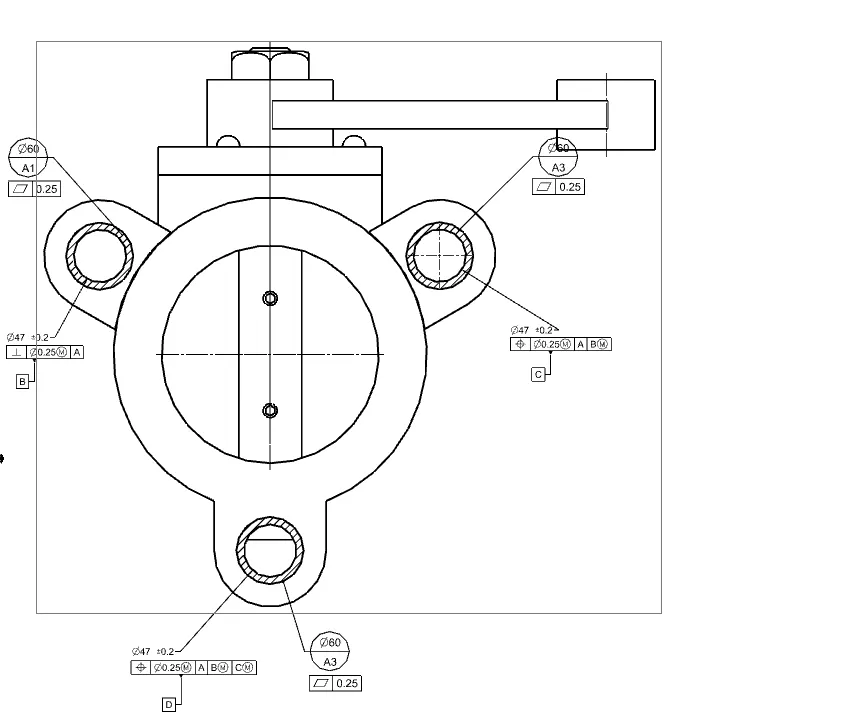
Any one of the hole surface on the A datum is chosen as the B datum. A dimensional tolerance between 46.8mm and 47.2mm diameter is applied to the hole. A perpendicularity tolerance of 0.25mm diameter on MMC condition with respect to A datum is also applied. Out of the other two holes, anyone is selected as the C datum with the same dimensional tolerance as the B datum. Additionally, a position tolerance of diameter 0.25mm on MMC condition with respect to A datum, and B datum on MMB condition.
Even though the assembly is fully constrained, we add the third hole as the D datum which later becomes useful with coaxiality of holes.
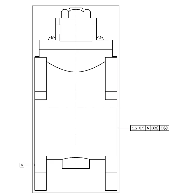
The surface opposite to A datum provided a profile of surface tolerance of 0.5mm with A datum, B and C datums on MMB condition as references.
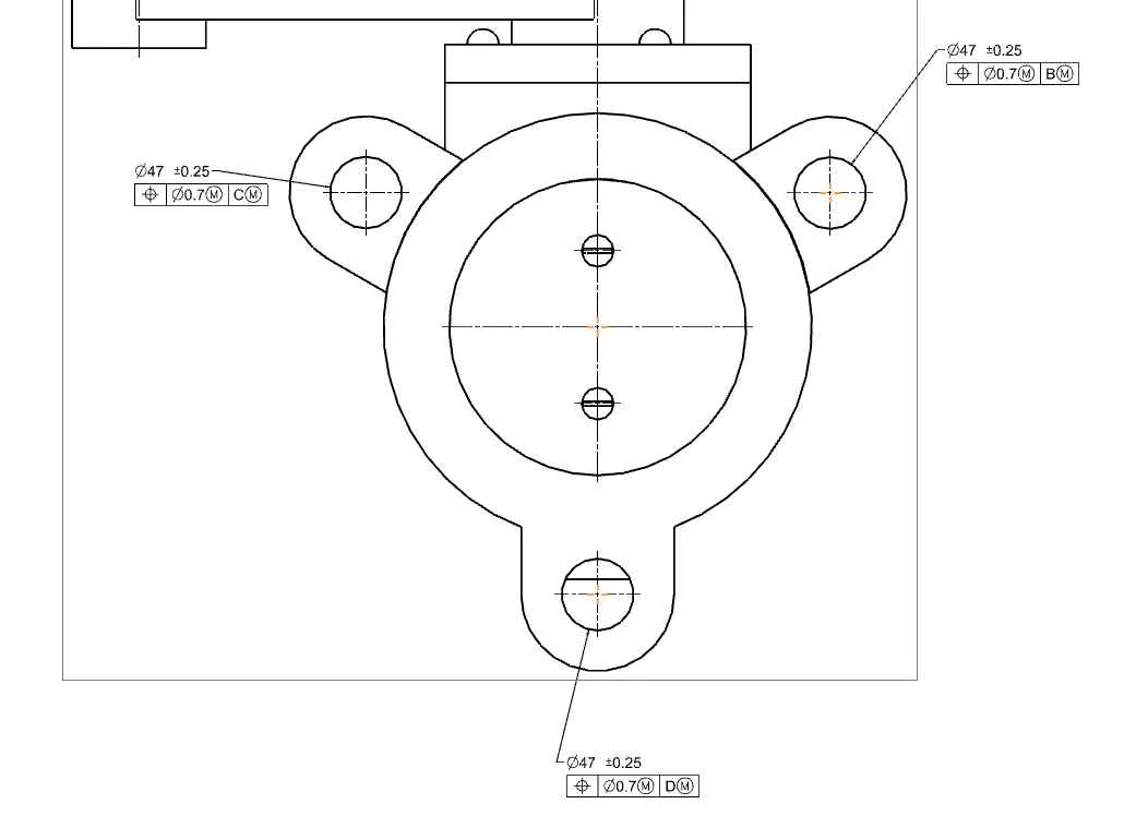
For the proper clamping, all three ears on the surface opposite to A datum must be coaxial with their counterpart ears on A datum. Each hole is provided a dimensional tolerance between 46.75mm and 47.25mm diameter with a carefully assigned position tolerance of 0.7mm diameter on MMC condition with respect to the counterpart as provided in the screenshot.
With that, we completely assigned proper GD &T symbols to the assembly drawing.
RESULT:
Successfully assembled all components of a Butterfly Valve and assigned proper GD & T symbols to the drawing in the drafting application.