Week 14 challenge
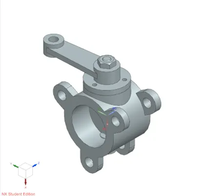
Butterfly valve (assembly):
Week 14
Introduction:
Butterfly valves are essential components in fluid control systems, providing reliable flow regulation and control. Their robust construction, variety of materials, and different operating modes make them suitable for a wide range of applications across industries. Proper design, adherence to geometric dimensioning and tolerances (GD&T), and careful consideration of the components like the body, shaft, retainer disc, flow control disc, and lever ensure efficient and accurate fluid control, contributing to the overall success and performance of systems utilizing butterfly valves.
Assembly:
Before assembling the components, make sure all the necessary components are present in a single folder.
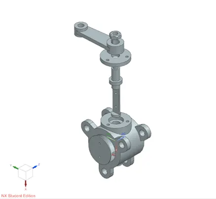
To start assembly of the butterfly valve, go to assemblies in the top ribbon. Use add component to add all the components.
But first, add the body of the butterfly valve and fix it.
Add the shaft and the disc. Move both the component out from the origin using move component command.
Using touch assembly constraint join the flat surface of the disc to the flat part of the shaft. Align the holes of the disc to the holes in the shaft using align constraint.
Bring the shaft-disc sub-assembly closer to the base. Using touch constraint, join the end of the shaft and the bottom cap of the base. Also touch the side curved surface area of the disc with the hollow surface of the body.
Bring in the lever in the assembly space. Align the axis of the shaft with the axis of the hollow cylinder with keyway slot. Align the surfaces of the keyways in both the shaft and lever.
Import the retainer and move it to its approximate position. Align the axis of the shaft and touch the flat surface of the retainer and the flat circular surface of the body. Align the axis of one of the bolting holes of the body to another bolting hole on the retainer.
Now, using touch constraint join the bottom surface of the hollow cylinder in lever with the top flat surface of the retainer.
Import the nut. Move and place it at an approximate location. Now, align the axis of the nut with the axis of the shaft.
Use the touch constraint to join the flat part of the nut with the top of the lever surface.
Tolerancing:
- As the assembly is quite large, scale it to a ratio of 1:2.
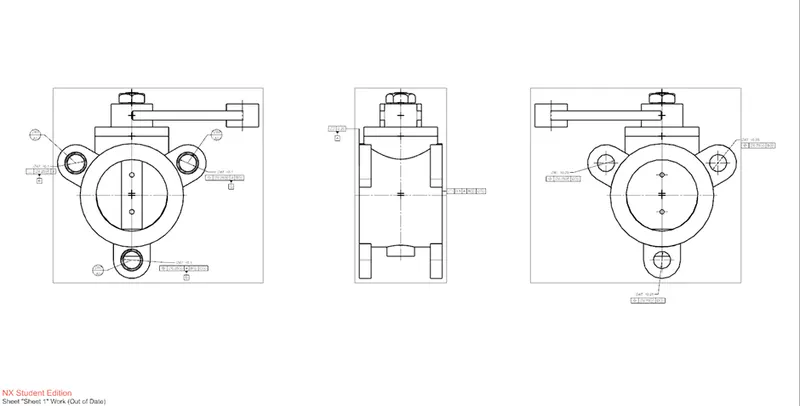
- The valve has to be coupled with the pipes using the flanges. Thus, we have to apply datum target areas around those holes. Call them datums A1, A2 and A3 with a diameter of 60mm.
- While working with scaled models, especially on datum targets, apply dimension only after hiding the externally drawn circle. It will display the original value of the feature. Not the scaled one.
- Combining these areas will constitute the overall datum A. To control the width of the body of the butterfly valve, apply profile tolerance to the opposite surface of the primary datum. Apply a flatness of 0.25mm.
- Add secondary and tertiary datums to any of the 2 mounting holes. Apply perpendicular tolerance to secondary datum with respect to datum A and position tolerance to tertiary datum with respect to primary and secondary datums.
- Add MMC wherever possible for extra tolerance.
- Add an extra datum D to the 3rd hole with position tolerance with respect to primary, secondary and tertiary datums.
- The holes on the flanges on the other side should be aligned with the holes on the datum A. For that, we will be applying position tolerance to each hole with respect to datum on its corresponding opposite hole so that its axis lies within it.
Assembly file: Assm_file.zip
Report: assm_report.docx