Week 14 challenge
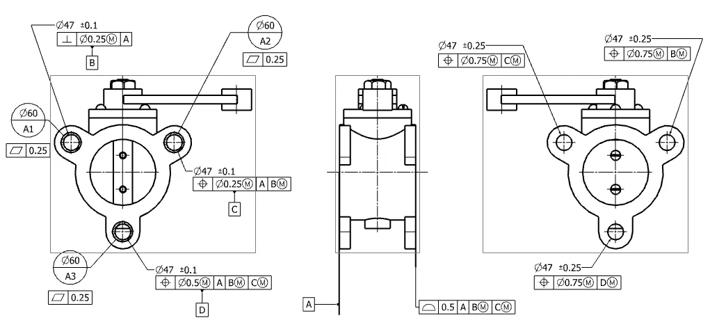
Aim: Assemble and apply GD&T to the butterfly valve assembly drawing.
Process:
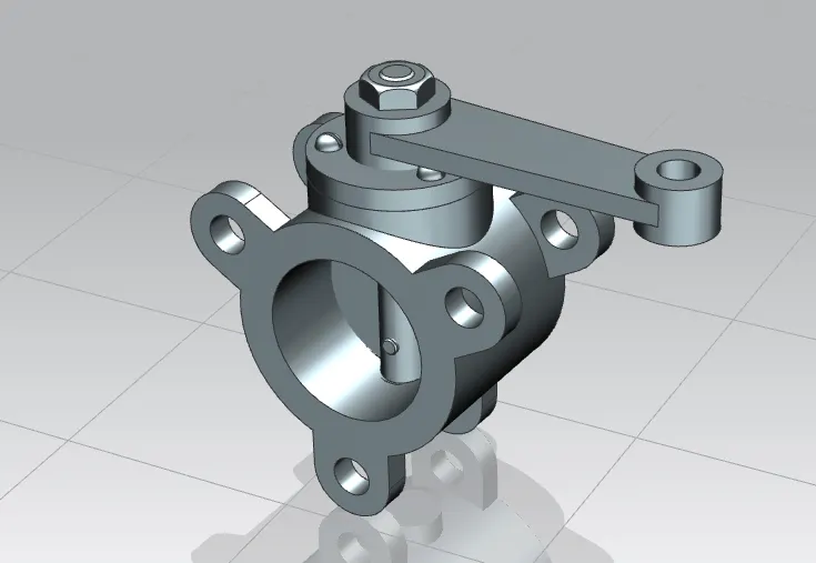
Adding all the part files to NX to assemble all the parts together and using various commands and constraints assemble them.
Name of the Parts:
1. Body
2. Shaft-Stem
3. Top Flange
4. Disc Plate
5. Lever Handle
6. Nut
7. Screw
1. Body
Butterfly valves generally have bodies that fit between two pipe flanges. The most common body designs are lug and wafer.
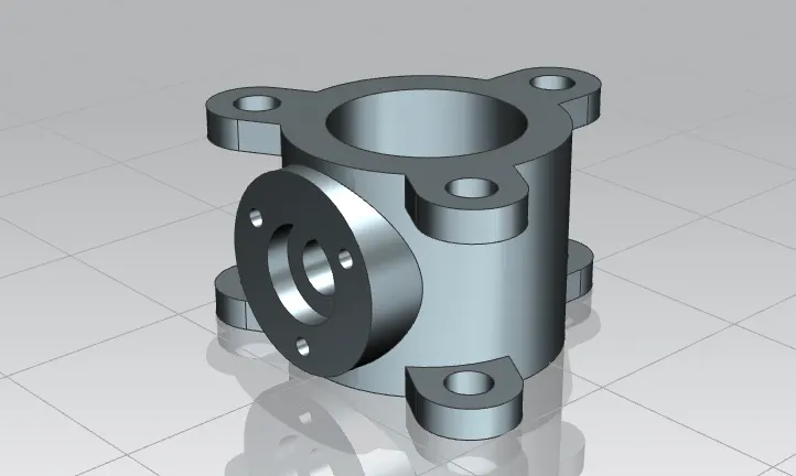
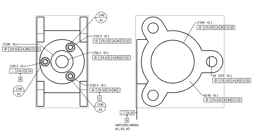
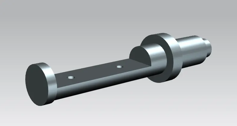
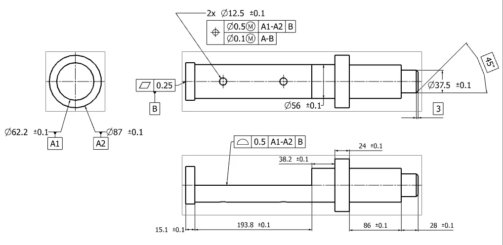
2. Stem/Shaft
The stem of the butterfly valve may be a one-piece shaft or a two-piece (split-stem) design.
3. Retainer
The retainer is a specially shaped washer that fits over the top of the valve spring. The keepers, or locks, fit into the valve stem grooves, holding the retainer and spring in place.
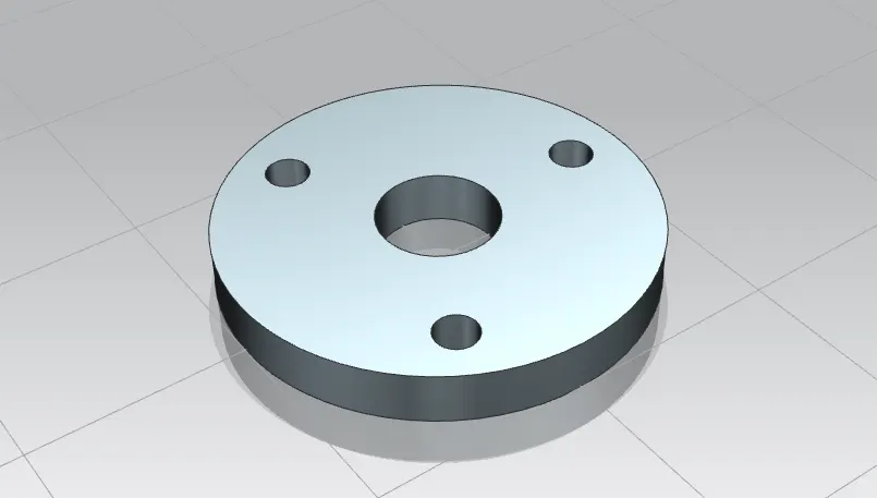
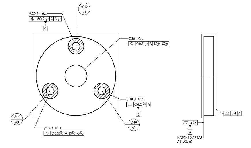
4. Disc
The flow closure member of a butterfly valve is the disk. The disk is the equivalent of a plug in a plug valve, gate in a gate valve or a ball in a ball valve. Rotating the disk one-quarter turn or 90 Degrees opens and closes the butterfly valve.
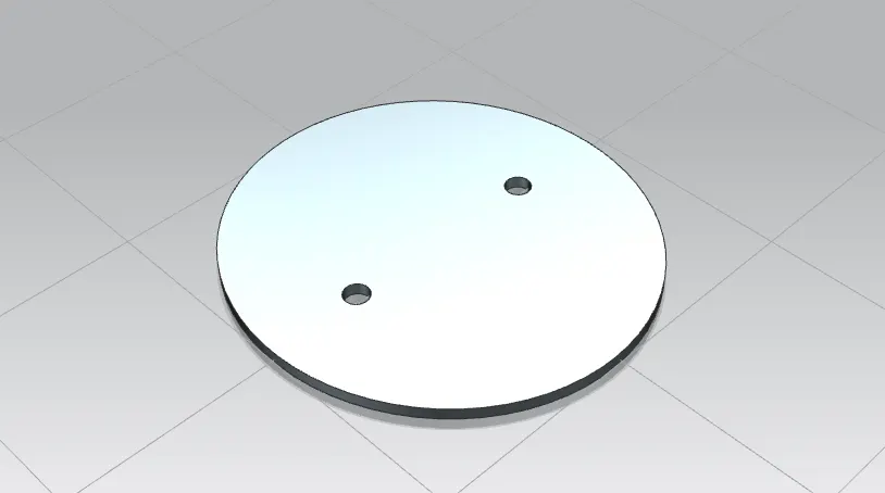
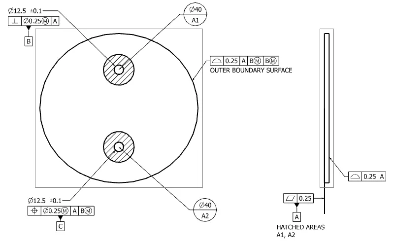
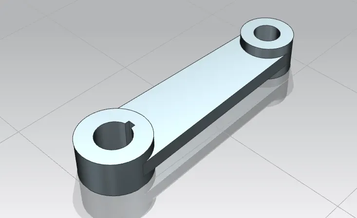
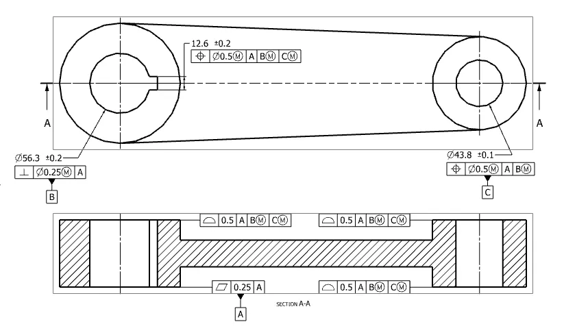
5. Lever
The hand lever is commonly used for small butterfly valves and is used to open and closed the valve. It is capable of being locked into a position of open, partially open, or closed.
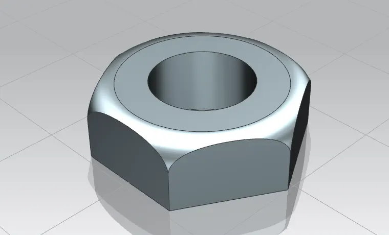
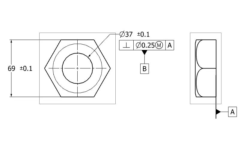
6. Nut
Nuts are almost always used in conjunction with a mating bolt to fasten multiple parts together. The two partners are kept together by a combination of their threads' friction.
Assembly
After modeling all the individual parts of the butterfly valve, all parts are assembled together in the assembly workbench of NX.
Conclusion
The Butterfly valve is successfully created and GD&T is applied to all the different parts and the assembly of the Butterfly valve.