Week 14 challenge
AIM:
The aim of the project is to model a butterfly_valve and to apply the GD&T for different parts of the butterfly_valve and assembly..
INRODUCTION TO BUTTERFLY VALVE :
A butterfly valve from a family of valve's called Quarter turn-valves... In the operation, the valve is fully opened or closed.. when the disc is rotated to a quarter-turn.. The " butterfly " is metal disc mounted on the rod.
When the valve is closed, the disc is turned so so that it completely blocks off the passage way.. When the valve is fully opens, the disc is rotated a quarter-turn so that it allows a almost un restricted passage of the fluid...
DESCRIPTION OF BUTTERFLY VALVE : The different parts of Butterfly valve are as follows:
1.BODY OF BUTTERFLY VALVE:
1. Initially, the sketch for a body of the butterfly valve is drawned using the circle tool in NX software.
2. After extruded the sketch which is drawn, the ears ofa Butterfly valve is drawn and then its copied on both the sides of cyclindrical portion..
3. Now, the datum plane option is used for create cyclidrical portion and the counter bore option is used to provide the counter bore to the part of specified dimensions.
4. Finally, the hole is provided for the mounting of the body and its saved in the required folder..
2. SHAFT :
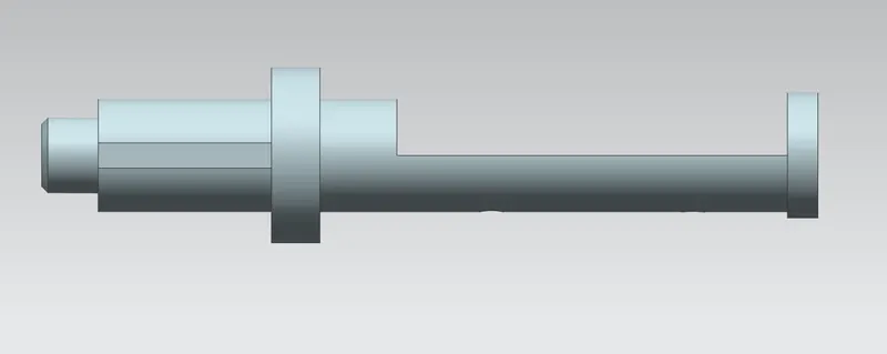
1. The 2D drawing given in figure is used to convert the 2d Sketch into 3D model with different operations.
2. The revolve option is used for create the shaft by rotating it through the 360°.
3. Now the extrude option (Subtract) is used to provide a recess in the front and rear portion of a shaft.
4. Finally, the two holes of 12.5 mm dia is provided in rear recess portion of a shaft and the part is saved in a required folder..
DRAWING OF THE SHAFT :
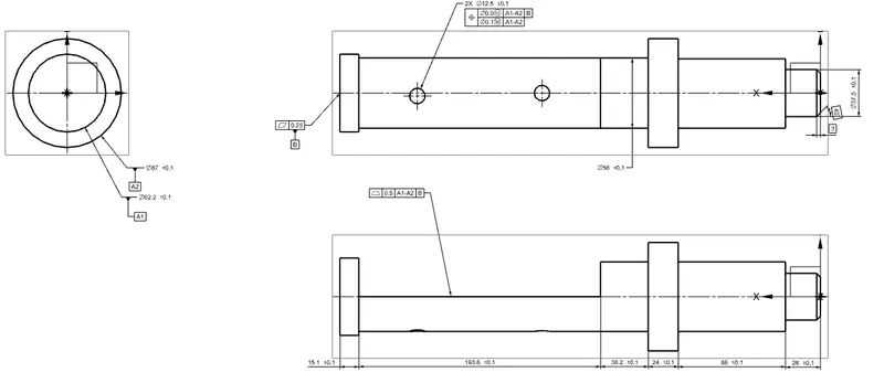
1.Here, Only two datums A , B are given since the movement of shaft is in one direction is required as per the it's function.
2. Datum A1 , A2 are given which comes in the contact with a body of the butterfly valve..
3. Datum B is provided at base of the shaft..
4. All the other tolerances like profile of a
surface,
flatness,
composition position tolerance and
the size tolerances are given to other features.
3.RETAINER:
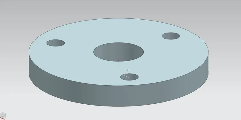
1. The 3D model of the Retainer is created with a help of given dimensions.
2. Initially,the concentric holes of 200mm , 56mm diameter are drawned and the other 3 circles of 20.3mm diameter is drawn with the help of 150mm BCD by using Pattern options.
Finally, the 2D sketch is extruded and the part is saved in the required folders.
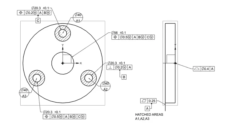
DRAWING OF RETAINER:
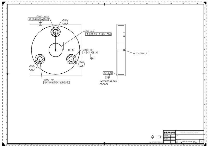
1. After the modeling, the part is taken to a drafting portion where the three datums A,B and C are applied.
2. Datum target areas A1,A2,A3 ( Primary datumA ) is applied to one side of the Retainer which comes in a contact with the upper portion of a body.
3. DatumB is applied to one of a holes of the retainer, where the bolts is inserted.
4. Datum-C is applied to a other hole of retainer.
5. Finally, the other tolerances like Perpendicularity,
position,
profile of a surface are applied to the other holes and the surface of the retainer, the drawing is saved in required folder.
4.DISC PLATE:
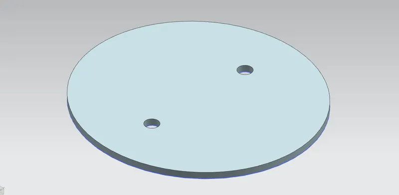
1. Initailly, with the help of 2D sketch drawing the disc plate is designed.
2. The ellipse with a minor, major radius is created and then the two holes of 12.5 diameter is given.
3. Finally, the sketch is extruded and the part is saved in the required folder.
DRAWING OF THE DISC PLATE:
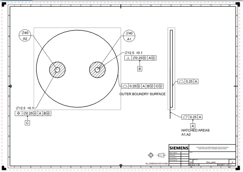
1. The datums are applied to the disc in the the drafting section.
2. Datum target Areas A1, A2( Primary Datum-A ) is given to one side of disc which comes in contact with the Stem / Shaft.
3. A datum B is given for one hole of a disc and the other datum is given to the other holes.
4. All the other tolerances like Perpendicularity tolerance to a datum B, position tolerance to datum C, profile of surface tolerance is given to a outer boundary surface.
5. LEVER :
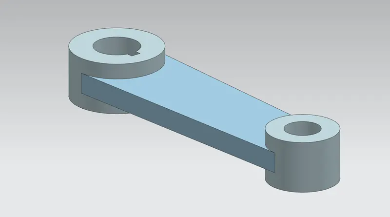
1. With the help of the 2D drawing of the lever, the 3D model of the lever is designed with help of different operations.
2. The different operation's used are Trim, Extrude, circle ,Tangency ...,etc.
3. Finally, the part is saved in a required folders..
DRAWING OF THE LEVER :
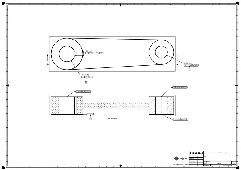
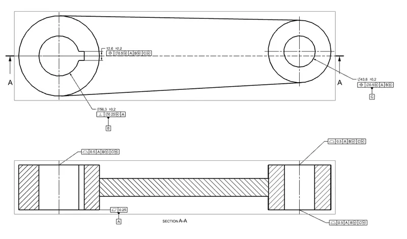
1. After the design of a lever, the drafting of lever is done for applying the GD & T.
2. Three datums A, B, C are applied to the part.
A datum - To the bottom surface of the lever that come in contact with other surface.
B datum - It is applied to the hole where bolt comes in contact.
C datum - It is applied to the other hole to the completely constraint a part.
Finally, all the other tolerances like position, Flatness, Profile of the surface are applied to the part.
6. NUT :
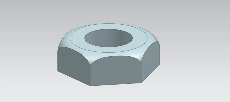
1. The 3D modeling of Nut is createwith the given dimensions.
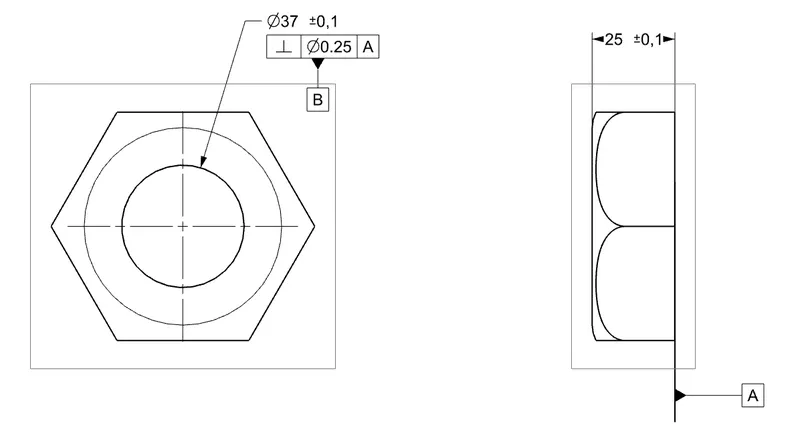
2. Initially the hexa-gonal shaped nut is extruded with the depth of 25mm and the hole of 37mm diameter.
3. Finally, the fillet of radius 10mm is provided by the using the revolve options,...
DRAWING OF THE NUT :
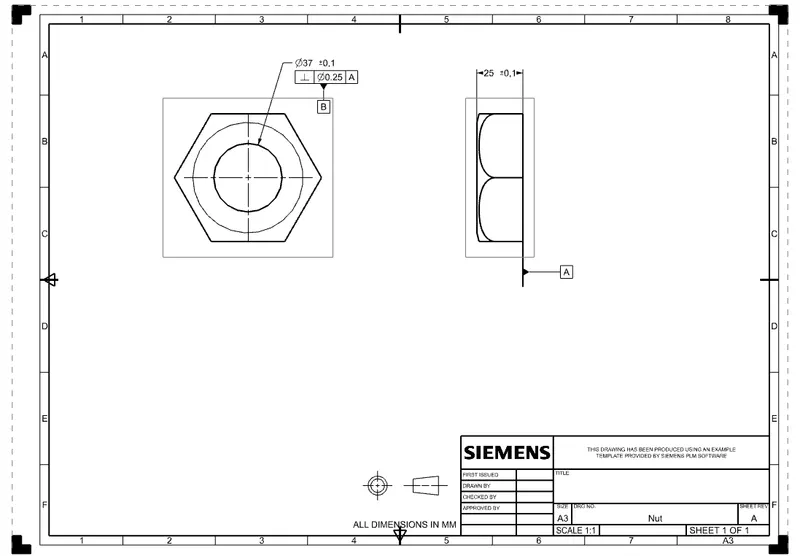
1. After finished creating the designed of nut, the drafting portion is opened for the applying GD & T to a nut.
2. Now, the datums A, B are applied to a base of the nut and the hole of a nut. Perpendicularity Tolerance of 0.25 is given to the hole of a nut.
7. ASSEMBLY OF THE BUTTERFLY VALVE:
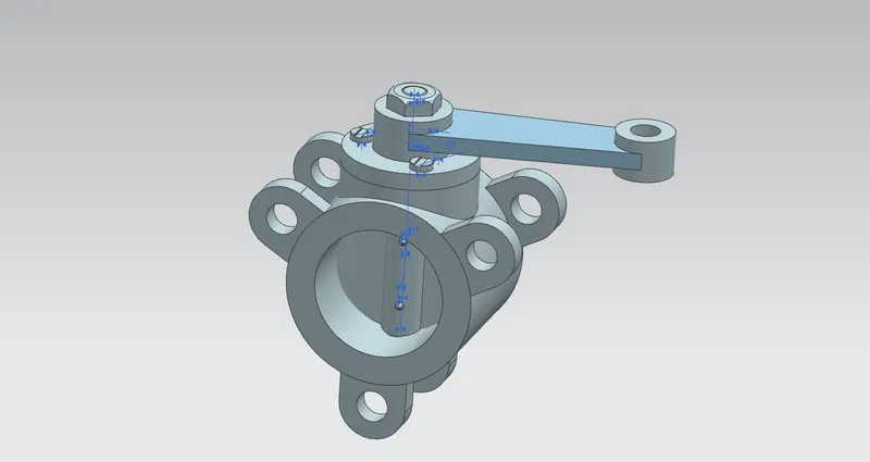
1. All the parts that are saved in a required folder is opened in a Add components tool boxs.
2. Now using the Move option and the Assembly Constraints option the different parts are joined together with a help of Align, touch, infer / Axis_operations.
3. Finally, the assembly of butterfly_valve is saved in a folder where the other part's were saved.
DRAWING OF THE ASSEMBLY :
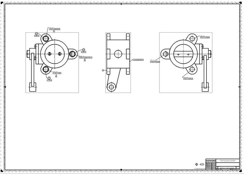
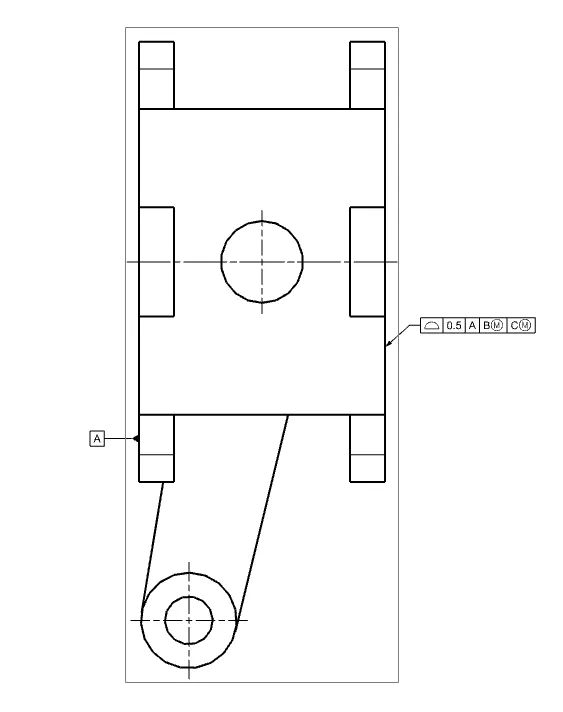
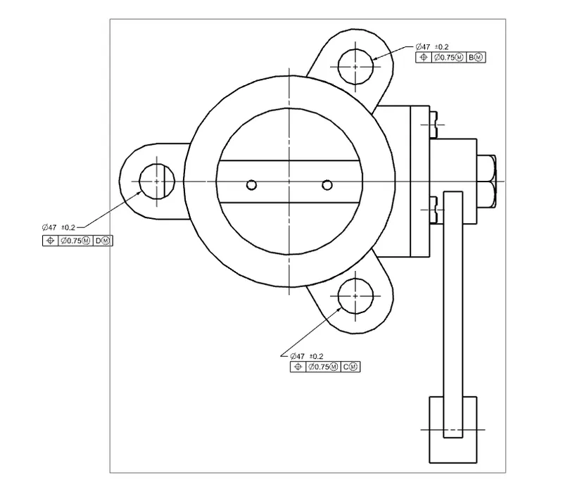
1. After the assembly of the butterfly valve, the datums A,B,C and D are given.
2. Datum target areas A1,A and A3 are given to the ears of a body with Perpendicularity tolerance and the position tolerance.
3. Other tolerances like profile of a surface, flatness are given. Position tolerances with respect to axis of B, C, D datums are the given corresponding to a ears of the body..
4. Finally, the GD & T of assembly is saved in required folder.
CONCLUSION :
Therefore, the Butterfly_valve is created and the GD&T are applied with a help of using UG NX-12 software.