Week 14 challenge
Objective:
To design of Butterfly Valve in appropriate dimension
To assemble all the individual parts of the butterfly valve by assigning suitable constraints.
To understand the concept of geometric tolerance and dimensioning.
Softwares Used :
Siemens NX 12
Introduction
Siemens NX 12: NX, formerly known as "Unigraphics", is an advanced high-end CAD/CAM/CAE, which has been owned since 2007 by Siemens PLM Software in 2000.
It is used, among other tasks, for:
Design (parametric and direct solid/surface modeling)
Engineering analysis (static; dynamic; electro-magnetic; thermal, using the FEA method; and fluid, using the finite volume method).
Manufacturing finished design by using included machining modules.
Butterfly Valve: A butterfly valve is a valve that isolates or regulates the flow of a fluid. The closing mechanism is a disk that rotates. A butterfly valve is from a family of valves called quarter-turn valves. In operation, the valve is fully open or closed when the disc is rotated a quarter turn. The "butterfly" is a metal disc mounted on a rod. When the valve is closed, the disc is turned so that it completely blocks off the passageway. When the valve is fully open, the disc is rotated a quarter turn so that it allows an almost unrestricted passage of the fluid. The valve may also be opened incrementally to throttle flow.
GD & T: Geometric Dimensioning and Tolerancing (GD&T) is a system for defining and communicating engineering tolerances. It uses symbolic language on engineering drawings and computer-generated three-dimensional solid models that explicitly describe nominal geometry and its allowable variation. It tells the manufacturing staff and machines what degree of accuracy and precision is needed on each controlled feature of the part. GD&T is used to define the nominal (theoretically perfect) geometry of parts and assemblies, to define the allowable variation in form and possible size of individual features, and to define the allowable variation between features. There are several standards available worldwide that describe the symbols and define the rules used in GD&T. One such standard is the American Society of Mechanical Engineers (ASME) Y14.5
Design methodology Flowchart :
Parts of Butterfly Valves :
Butterfly valve body
Shaft
Disc Plate
Lever
Retainer
Nut
Bolt
Commands Used :
Line: This feature allows us to create a straight line. The line can be a solid line or a construction line.
Circle: This feature allows us to create circles.
Rectangle: This feature allows us to create squares or rectangles.
Arc: This allows us to create an arc.
Trim: This is used to trim sketches.
Extrude Bose: This feature allows us to create solid bodies.
Revolve: Revolves add or remove material by revolving one or more profiles around a centreline. You can create revolved boss/bases, revolved cuts, or revolved surfaces. Axis of revolution can be 3d sketch.
Circular Pattern: This allows us to create a pattern in a circle
Fillet: This is used to create circular edges.
Hole: A Hole feature is used to create holes on the model.
Unite: Unite is used to convert two or more solid bodies into one solid body.
1. Butterfly valve body :
The body is the housing for the internal components and it is the main part of the butterfly valve. The body connects to two pipes on its two sides and it regulates to flow. For the creation of this part, simple features like to revolve, extrude, and move objects are used in the modeling application of NX.
Features used to create the Butterfly Valve :
Sketch
Extrude
datum plane and coordinate
counterhole Bore
unite
2. Shaft :
It is another important component of the butterfly valve. It inserts into the body of the valve and sits perpendicular to the direction of flow. It holds the disc inside the body and is clamped with the lever outside the body. It is created using simple features like revolve and extrudes features in the NX modeling environment. After the part creation is completed, the drawing is created in the drafting application of NX, and GD&T is applied using the features of NX. For this shaft, position tolerance should be given to the holes which hold the disc, a profile of the surface should be applied to the surface where the disc sits, and position tolerance for the cylindrical body of the shaft concerning the defined datums. Composite position tolerance is applied in the case of disc positioning holes as it repeats creating a pattern.
Features used to create Shaft :
Sketch
Revolve
Datum plane
Extrude
chamfer
3. Disc Plate :
This disc plate is the main component of the butterfly valve which regulates the flow in the valve. The orientation of this disc determines the flow rate of the fluid. It is not perfectly circular, rather it is elliptical in profile. The holes in it help to position it properly on the shaft created earlier. A simple feature like extrude can create this part in NX. To apply GD&T for this part, the primary datum is defined on the surface where it comes in contact with the surface of the shaft, and perpendicular and perpendicular tolerances are applied as per the requirement. As the cost increases, while machining the entire contact surface, small circular datum targets are created and GD&T is applied to reduce the manufacturing cost.
Features used to create Shaft :
Sketch
Extrude
4. Lever :
A lever is a handle that is used to rotate to regulate the flow. It is attached to the shaft with the help of a key to fixing it in position concerning it. So when it is rotated, the shaft rotates which in turn rotates the disc and regulates the flow inside the pipe. It is created using simple features like extrude in NX after the proper base sketch is created. For the application of GD&T on the lever, a section view is also created to show how different datums are defined and tolerances are provided. Position tolerance is applied to the proper holes after the perpendicular tolerance is applied to the first hole. To control the key slot, small tolerance is applied to the width of it. Profile tolerances are provided to the surfaces which come to contact with other parts as per the requirement.
Features used to create Shaft :
Sketch
Extrude
5. Retainer :
This part helps to retain or to fix the shaft with the body of the butterfly valve. It prevents the shaft from coming out of the body and keeps it in position for the proper functioning of the disc inside the body. The creation of the retainer plate involves only a simple feature like extrude in NX. For the GD&T application in the retainer plate, similar steps are followed as in the case of the disc. Primary, secondary and tertiary datums are defined properly as per the design intent, and datum targets are applied to the holes. Perpendicular and position tolerances are applied to lock the DOF of the retainer in position. A profile tolerance is also applied to control the upper surface of the retainer.
Features used to create Shaft :
Sketch
Extrude
6. Nut :
It is the last part that helps to fix the lever in position with the stem. It allows to keep it in position or to disassemble whenever required. It is created using simple extrude and revolve features in NX. To apply GD&T for this nut, the primary datum is defined on the surface which comes in contact with the lever. Perpendicular tolerance is applied to the hole or the thread and is defined as datum B. Size tolerance is also applied to the thickness of the nut.
Features used to create Shaft :
Sketch
Extrude
Revolve
ASSEMBLY OF BUTTER FLY VALVE :
WORKBENCH USED TO ASSEMBLE :
Assembly workbench
COMMANDS USED TO ASSEMBLY :
MOVE COMPONENTS
ASSEMBLY CONSTRAINTS
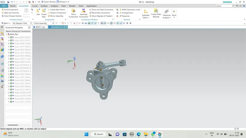
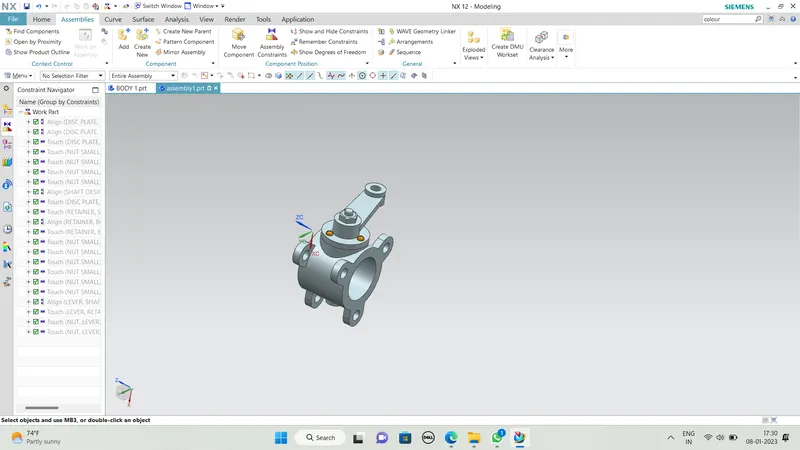
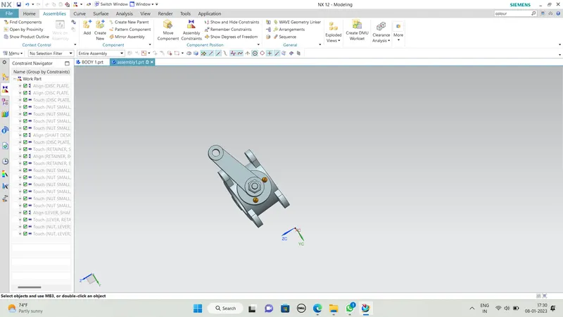
BUTTERFLY ASSEMBLY PICTURES :
DRAFTING OF BUTTERFLY VALVE :
