Week 14 challenge
BUTTERFLY VALVE ASSEMBLY:
- Open New & select Assembly option.
- Intially copy all the parts of the Butterfly Valve in Nx-cad from Add Component option.
BUTTERFLY VALVE UNASSEMBLED PARTS:
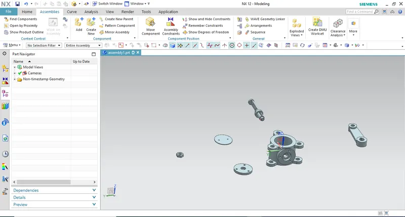
- The above figure depicts all the parts of butterfly assembly which as to be assembled.
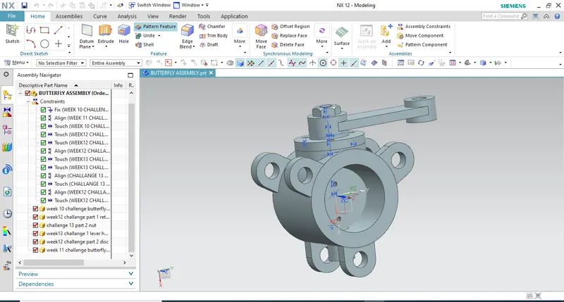
STEPS TO BE FOLLOWED FOR BUTTERFLY VALVE ASSEMBLY:
- Intailly fix the body of the butterfly valve.
- The next step is to go to Assembly Constraints select touch align & in orientation select Infer center/axis align the center axis of shaft & the body & then select the face of shaft & body then apply & then ok the body & shaft wil be assembled.
- The next step is to go to Assembly Constraints select touch align & in orientation select Infer center/axis align the center axis of retainer & the body & then select the face of body & retainer then apply & then ok ,the retainer wil be assembled.
- Then go to Assembly Constraints select touch align & in orientation select Infer center/axis align the center axis of disc & the shaft & then select the face of disc & shaft then apply & then ok ,the disc wil be assembled on shaft.
- The next step is to go to Assembly Constraints select touch align & in orientation select Infer center/axis align the center axis of Lever Handle & the retainer & then select the face of lever handle & retainer then apply & then ok, the lever handle wil be assembled on retainer.
- The Final step is to go to Assembly Constraints select touch align & in orientation select Infer center/axis align the center axis of nut & the lever handle & then select the face of nut & lever handle then apply & then ok, the nut wil be assembled on the lever handle
- The assembly is finished where the design is shown above.
Front view of Butterfly valve assembly:
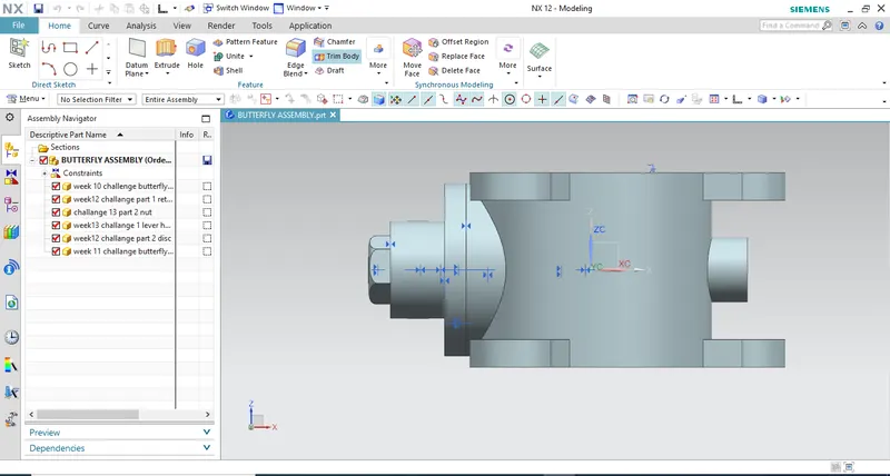
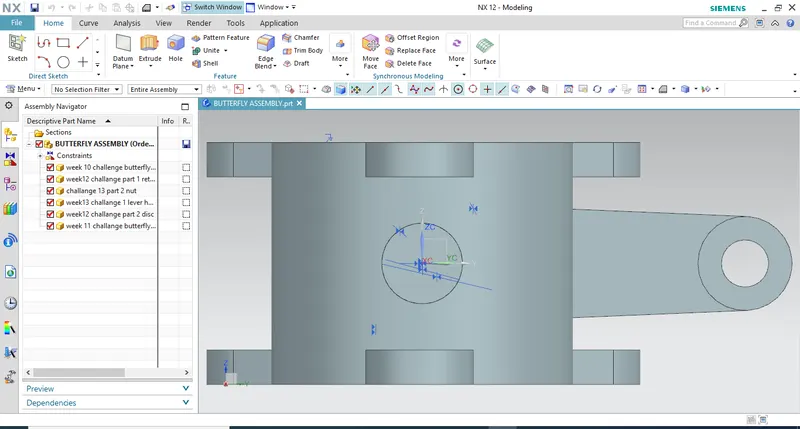
Top view of Butterfly valve assembly:
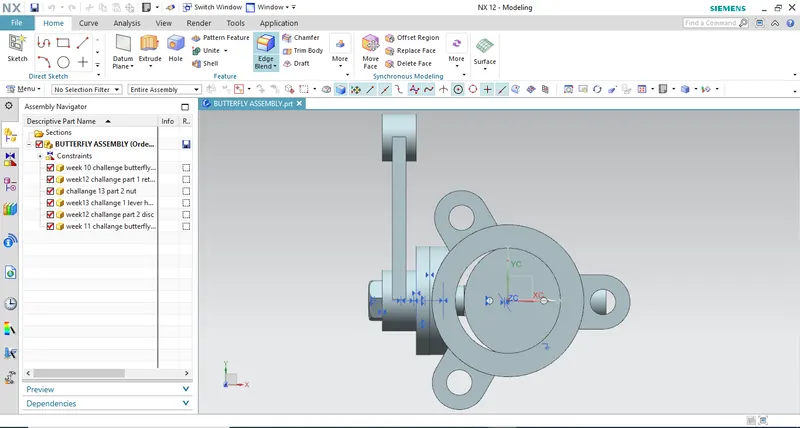
Side view of Butterfly valve assembly:
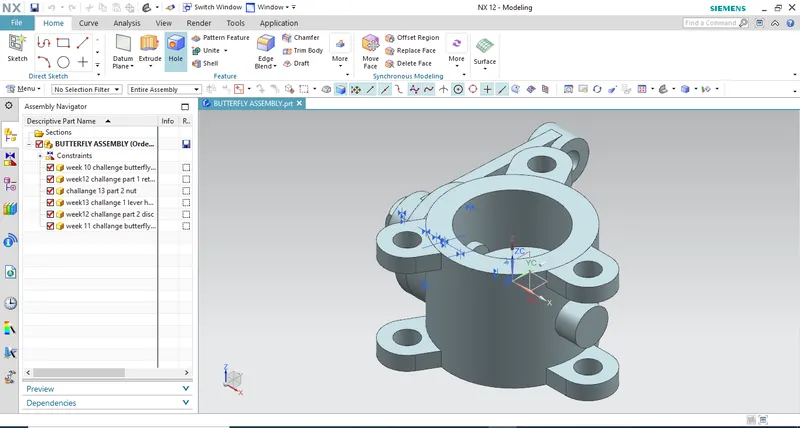
Isometric view of Butterfly valve assembly:
GD & T FOR BUTTERFLY ASSEMBLY:

- After the design of assembly of butterfly valve has been finished gd & t has to be done.
- Go to applications select drafting.
- In drafting right click select the base view & A0 size sheet & in orientation make it to 1:2 ratio.
- Intially keep the the model i required shape to apply datums.
- After the required shape has been obtained, project the projected view of that shape & also project the opposite shape of base view has been projected from the projected view.
- Apply the datum A for the I projected view on left side of the surface.
- Then create 2 arc circle for all the three circles & hatch them
- Next give the dimension of arc circle as diameter 40mm & datum target for top right side of the circle as A1, top left circle as diameter of 40mm & A2 & bottom circle as diameter of 40mm & A3.
- Give all circles the flatness of 0.25mm.
- In the base view select the top right of outside circle and give dimension as Dia of 47mm with tolerence of +/- 0.1 , & give the symbol of penpendicularity for dia of 0.25mm with maximum material condition & A & mark it as datum B
- In the base view select the top left of outside circle and give dimension as Dia of 47mm with tolerence of +/- 0.1 , & give the symbol of position for dia of 0.25mm with maximum material condition & A & B with maximum material condition & mark it as datum C.
- In the base view select the bottom of outside circle and give dimension as Dia of 47mm with tolerence of +/- 0.1 , & give the symbol of position for dia of 0.5mm with maximum material condition & A & B with maximum material condition & C with maximum material condition mark it as datum D.
- Give the flatness symbol for the right side of I projected view for about 0.5mm & A & B with maximum material condition & C with maximum material condition.
- For the II projected view i.e., opoosite view of base view, for the left circle give the dimension of 47mm With tolerence of +/- 0.25 & give symbol of position & dia of 0.75mm with maximum material condition & C with maximum material condition.
- In the same view for the right circle give the dimension of 47mm With tolerence of +/- 0.25 & give symbol of position & dia of 0.75mm with maximum material condition & B with maximum material condition.
- In the same view for the bottom circle give the dimension of 47mm With tolerence of +/- 0.25 & give symbol of position & dia of 0.75mm with maximum material condition & D with maximum material condition.
- Finally all the GD & T symbol as been given for the BUTTERFLY VALVE ASSEMBLY which is shown above.