Week 12 - Symmetry vs Wedge vs HP equation
* This challenege is continuation of last challenege, were in flow through pipe is simulated using wedge boundary condition. Velocity profile as well as shear stress are plotted and the results are validated with Haigen poisuelli flow. In this challenge for same above problem instead of wedge boundary condition symmetry boundary conditions are used and the results are observed to check whether there is any change in the results can be seen when symmetry boundary condition is used.
* Aim of the challenge: To apply symmetry boundary conditions at angle of sector = 10°, 25°, 45°. Run the simulation and observe the result.
As a small recap of things in the previous challenge, flow of water at 25 °C is considered,
we had for water at 25°C Dynamic viscosity, `mu = 0.890*10^-3 (kg)/(m-s)`
also Kinematic viscosity, `nu = 0.893*10^-6 m^2/s`
water is considered to be flowing with a inlet velocity, U = 0.05 m/s. Diameter of the pipe is considered as, D = 0.025 m.
hence Reynolds number, `Re = (U*D)/nu`
therefore Re = 0.05*0.025/0.893*10^-6 = 1399.7 = 1400
For an internal flow reynolds number less than 2300 is considered as laminar flow, hence the flow we are studying is laminar.
For laminar flow we had the hydrodynamic entry length, `L_h = 0.05*Re*D` = 0.05*1400*0.025 = 1.75 m
so for a length of 1.75 m from the inlet the flow is not fully developed and hence we got incomplete velocity profiles till this length and after this length we got a complete parabola as the velocity profile.
* Setup: In this challenge the blockMeshDict file specifing the symmetry boundary conditions for the front and back face of the wedge considered is generated through file parsing using matlab. Below shows the matlab codes, for generating a profile for angle = 10°. Changes are made on line number 136 and line number 146 where in the boundary condition of type symmetry is specified instead of wedge.
Also in previous challenge were wedge boundary condition is used, in there a total of 60 cells were used in y-direction. For a end time of 50 sec, 0.007 sec of time step is used. If the same time step is used after applying the symmetry boundary condition for given number of cells in y-direction, the solution becomes unstable because the courant number shoots above the maximum value. So the number of cells along y-direction is reduced to 20 and same time step of 0.007 sec is used.
clear all
close all
clc

% Creating blockMeshDict file for wedge creation;

% Defining the Diameter of pipe in meters;
D = 0.025;

% U = 0.05 m/s , nu = 0.893e-06, D = 0.025 m
% R = 0.05*0.025/0.893*e-06
% Defining the reynolds number considering a laminar flow
R = 1400;

% Defining the length of the pipe;
% L = L_h + tol, Length is hrydrodynamic entry length plus a tolerance;
% L_h = 0.05*R*D;

L = (0.05*R*D)+0.75;

% Defining the wedge angle(Degree);
theta = 10;

% Defining the co-ordiantes for wedge creation;
z = (D/2)*sind(theta/2);
y = (D/2)*cosd(theta/2);

% Defining grading factor along x,y and z direction;
g_x = 1;
g_y = 0.1;
g_z = 1;


% File parsing for BlockMeshDict file;

f1 = fopen('output.txt','w');

% Header creation;
fprintf(f1,'%s','/*--------------------------------*- C++ -*----------------------------------*\');
fprintf(f1,'\n');
fprintf(f1,'%s','  =========                 |');
fprintf(f1,'\n');
fprintf(f1,'%s','  \\      /  F ield         | OpenFOAM: The Open Source CFD Toolbox');
fprintf(f1,'\n');
fprintf(f1,'%s','   \\    /   O peration     | Website:  https://openfoam.org');
fprintf(f1,'\n');
fprintf(f1,'%s','    \\  /    A nd           | Version:  6');
fprintf(f1,'\n');
fprintf(f1,'%s','     \\/     M anipulation  |');
fprintf(f1,'\n');
fprintf(f1,'%s','\*---------------------------------------------------------------------------*/');
fprintf(f1,'\n');
fprintf(f1,'%s','FoamFile');
fprintf(f1,'\n');
fprintf(f1,'%s','{');
fprintf(f1,'\n');
fprintf(f1,'%s','    version     2.0;');
fprintf(f1,'\n');
fprintf(f1,'%s','    format      ascii;');
fprintf(f1,'\n');
fprintf(f1,'%s','    class       dictionary;');
fprintf(f1,'\n');
fprintf(f1,'%s','    object      blockMeshDict;');
fprintf(f1,'\n');
fprintf(f1,'%s','}');
fprintf(f1,'\n');
fprintf(f1,'%s','// * * * * * * * * * * * * * * * * * * * * * * * * * * * * * * * * * * * * * //');
fprintf(f1,'\n');
fprintf(f1,'\n');
fprintf(f1,'%s','convertToMeters 1;');
fprintf(f1,'\n');
fprintf(f1,'\n');

% vertice creation;
fprintf(f1,'%s','vertices');
fprintf(f1,'\n');
fprintf(f1,'(\n');
fprintf(f1,'    (%d %d %d)\n',0,0,0);
fprintf(f1,'    (%d %d %d)\n',0,y,z);
fprintf(f1,'    (%d %d %d)\n',0,y,-z);
fprintf(f1,'    (%d %d %d)\n',L,0,0);
fprintf(f1,'    (%d %d %d)\n',L,y,z);
fprintf(f1,'    (%d %d %d)\n',L,y,-z);
fprintf(f1,');\n\n');

% Block creation;
fprintf(f1,'blocks\n');
fprintf(f1,'(\n');
fprintf(f1,'    hex (0 3 5 2 0 3 4 1) (400 20 1) simpleGrading (%d %d %d)\n',g_x,g_y,g_z);
fprintf(f1,');\n\n');

% Edge creation;
fprintf(f1,'edges\n');
fprintf(f1,'(\n');
fprintf(f1,'    arc 1 2 (0 %d 0)\n',D/2);
fprintf(f1,'    arc 4 5 (%d %d 0)\n',L,D/2);
fprintf(f1,');\n\n');

% Boundary creation;
fprintf(f1,'boundary\n');
fprintf(f1,'(\n');

%inlet face;
fprintf(f1,'    inletwall\n');
fprintf(f1,'    {\n');
fprintf(f1,'        type patch;\n');
fprintf(f1,'        faces\n');
fprintf(f1,'        (\n');
fprintf(f1,'            (2 0 0 1)\n');
fprintf(f1,'        );\n');
fprintf(f1,'    }\n');

%Outlet face;
fprintf(f1,'    outletwall\n');
fprintf(f1,'    {\n');
fprintf(f1,'        type patch;\n');
fprintf(f1,'        faces\n');
fprintf(f1,'        (\n');
fprintf(f1,'            (4 3 3 5)\n');
fprintf(f1,'        );\n');
fprintf(f1,'    }\n');

%Top face;
fprintf(f1,'    Noslipwall\n');
fprintf(f1,'    {\n');
fprintf(f1,'        type wall;\n');
fprintf(f1,'        faces\n');
fprintf(f1,'        (\n');
fprintf(f1,'            (5 2 1 4)\n');
fprintf(f1,'        );\n');
fprintf(f1,'    }\n');

%wedge front;
fprintf(f1,'    front\n');
fprintf(f1,'    {\n');
fprintf(f1,'        type symmetry;\n');
fprintf(f1,'        faces\n');
fprintf(f1,'        (\n');
fprintf(f1,'            (1 0 3 4)\n');
fprintf(f1,'        );\n');
fprintf(f1,'    }\n');

%wedge Back;
fprintf(f1,'    Back\n');
fprintf(f1,'    {\n');
fprintf(f1,'        type symmetry;\n');
fprintf(f1,'        faces\n');
fprintf(f1,'        (\n');
fprintf(f1,'            (2 5 3 0)\n');
fprintf(f1,'        );\n');
fprintf(f1,'    }\n');

%wedge axis;
fprintf(f1,'    axis\n');
fprintf(f1,'    {\n');
fprintf(f1,'        type empty;\n');
fprintf(f1,'        faces\n');
fprintf(f1,'        (\n');
fprintf(f1,'            (0 3 3 0)\n');
fprintf(f1,'        );\n');
fprintf(f1,'    }\n');
fprintf(f1,');\n\n');


%Patchpairs;
fprintf(f1,'mergePatchPairs\n');
fprintf(f1,'(\n');
fprintf(f1,');\n\n')

fprintf(f1,'// ************************************************************************* //');

fclose(f1);
The output text file that is generated by running the above codes is used as blockMeshDict file. This file is replaced in the system directory of icoFoam case setup. Along with the blockMeshDict file there are other file on which the same symmetry boundary conditions need to be applied, those are the p and U file of the 0 directory. Other than this nothing is changed.
p file:
/*--------------------------------*- C++ -*----------------------------------*\
  =========                 |
  \\      /  F ield         | OpenFOAM: The Open Source CFD Toolbox
   \\    /   O peration     | Website:  https://openfoam.org
    \\  /    A nd           | Version:  6
     \\/     M anipulation  |
\*---------------------------------------------------------------------------*/
FoamFile
{
    version     2.0;
    format      ascii;
    class       volScalarField;
    object      p;
}
// * * * * * * * * * * * * * * * * * * * * * * * * * * * * * * * * * * * * * //

dimensions      [0 2 -2 0 0 0 0];

internalField   uniform 0;

boundaryField
{
    inletwall
    {
        type            zeroGradient;
    }

    outletwall
    {
        type            fixedValue;
        value           uniform 1;
    }

    Noslipwall
    {
        type            zeroGradient;
    }

    front
    {
        type            symmetry;
    }

    Back
    {
        type            symmetry;
    }

    axis
    {
        type            empty;
    }
}

// ************************************************************************* //
U file:
/*--------------------------------*- C++ -*----------------------------------*\
  =========                 |
  \\      /  F ield         | OpenFOAM: The Open Source CFD Toolbox
   \\    /   O peration     | Website:  https://openfoam.org
    \\  /    A nd           | Version:  6
     \\/     M anipulation  |
\*---------------------------------------------------------------------------*/
FoamFile
{
    version     2.0;
    format      ascii;
    class       volVectorField;
    object      U;
}
// * * * * * * * * * * * * * * * * * * * * * * * * * * * * * * * * * * * * * //

dimensions      [0 1 -1 0 0 0 0];

internalField   uniform (0 0 0);

boundaryField
{
    inletwall
    {
        type            fixedValue;
        value           uniform (0.05 0 0);
    }

    outletwall
    {
        type            zeroGradient;
    }

    Noslipwall
    {
        type            fixedValue;
        value           uniform (0 0 0);
    }

    front
    {
        type            symmetry;
    }

    Back
    {
        type            symmetry;
    }

    axis
    {
        type            empty;
    }
}

// ************************************************************************* //
* blockMesh is typed on the command window to generate the geometry, generated geometry i.e, sector with angle = 10° is observed in paraView.
Below is the snip of the of the sector generated for angle = 10°
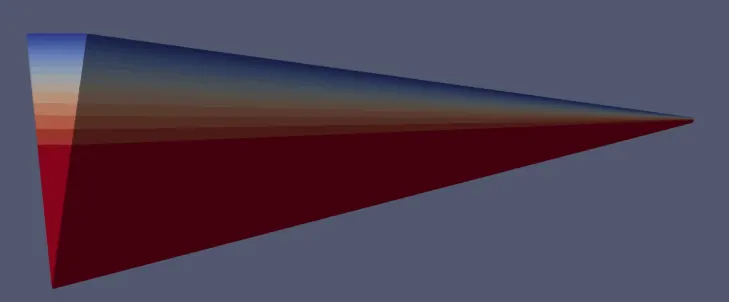
Simulation is run by typing the icoFoam in the command window. After completing the simulation a plot of velocity profile is taken that too at a distance more than 1.75 m from the inlet, so that we get a velocity profile of fully developed flow. Below is the snip of the same,
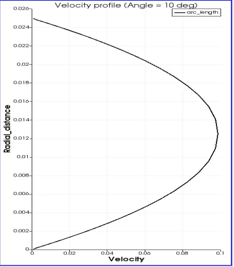
Execution time = 1158.02 sec.
Clock time = 2261 sec.
Mean courant number = 0.0563993.
Max courant number = 0.140986.
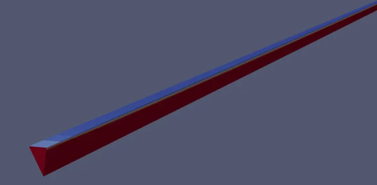
* Changes are made on line number 22 to include angle = 25° and 45° and matlab codes are run to generate the output text file, which inturn is used as blockMeshDict file.
The geometry generated for angle = 25° is as shown below,
* Velocity profile:
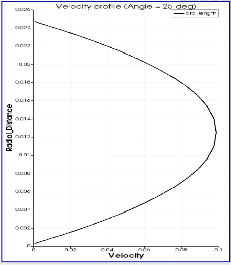
Execution time = 1877.35 sec.
Clock time = 3470 sec.
Mean courant number = 0.0563993.
Max courant number = 0.142142.
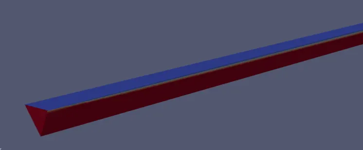
* Geometry for angle = 45°
* Velocity profile:
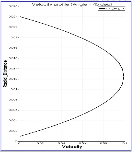
Execution time = 1407.22 sec.
Clock time = 2581 sec.
Mean courant number = 0.05639.
Max courant number = 0.144934.
* Observation: Velocity profiles taken for different angles are the same. The only difference that can be noted is of the difference in the execution time and clock time. As angle increases it is seen increasing. Hence we can conclude that as we change from wedge boundary condition to symmetry boundary condition the result remains the same.