Week 12 - Symmetry vs Wedge vs HP equation
Objective: To construct a BlockMesh dict file using MATLAB interface for a flow of fluid through a circular pipe by considering a symmetric plane condition. And also need to find the behiaviour for various cut sections of cylinder included angles.
Approach:
Coordinates or nodes considered for the axis-symmetric flow through pipe is the image as shown below:
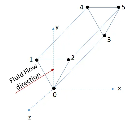
axis indication:
Z-direction- "-ve" z-direction fluid flows.
y-direction- radial direction of the pipe.
faces indication:
0-1-2: entry of the fluid considered
3-4-5: exit of the fluid considered
1-2-4-5: wall of the cylinder
0-2-3-5: Right symmetry plane of the cylinder
0-1-4-5: Left symmetry of the cylinder
0-3-3-0: empty face
Inputted Data for the given case:
Fluid considered is 'Water'
Density is 1000 `(kg)/m^3`
kinetic Viscosity is `10^(-6) m^2/s`
Reynold's number to stay in laminar phase for a duct flow should be less than or equal to 2000. So, reynold's number considered here is 2000.
Radius of the cylinder: 5 mm or 0.005 m
Length of the cylinder: 1500 mm or 1.5 m
Note:- Wedge Angle: 4 different wedge angles are considered namely 4 degrees, 10 degrees, 25 degrees and 45 degrees respectively for comparision. (Note: Data to be entered in degrees in MATLAB file)
Cell Grading near the wall is 0.2
Number of nodes in radial direction: 20
Number of nodes in flow direction or axial direction: 100
Number of nodes in x-direction: 1
Boundary conditions:
on entry face:
Velocity: Uniform and fixed velocity of 0.2 m/s
Pressure: Zero gradient near the face
on exit face:
Velocity: Zero gradient near the face
Pressure: Uniform and fixed pressure of 0 `N/m^2`
near the wall:
Velocity: No slip condition
Pressure: Zero gradient near the face
near the wedge faces:
Velocity: symmetry plane condition used
Pressure: symmetry plane condition used
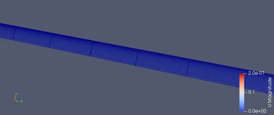
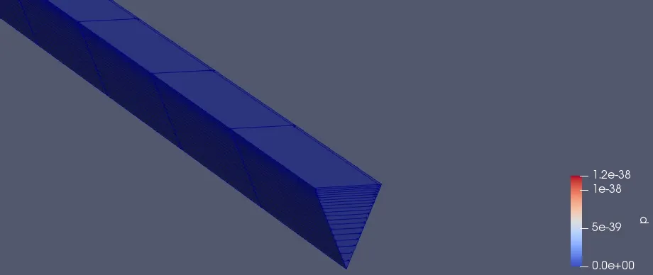
Below indicates the meshed image for the developed MATLAB file for an included angle of 4 degrees:
Below indicates MATLAB file for the above said blockMesh dict file:
%% Week-11 Challenge, Simulation of pipe through open foam

clc
clearvars

%% Inputs

alpha=input('enter a wedge angle');
% alpha=4;
t=alpha*pi/180;
r=input('enter radius of the cross section');
% r=0.5;
% l=150;
% g=0.2;
% x=1;
% y=20;
% z=100;
 l=input('enter length of the cylinder');
 g=input('enter grading scheme near walls');
x=input('enter number of grid points in x-direction');
y=input('enter number of grid points in y-direction');
z=input('enter number of grid points in z-direction');


A=fopen('blockMeshDict.txt','w')
fprintf(A,'/*--------------------------------*- C++ -*----------------------------------*%s','\');
fprintf(A,'\n=========                 |');
fprintf(A,'\n%s%s      /  F ield         | OpenFOAM: The Open Source CFD Toolbox','\','\');
fprintf(A,'\n %s%s    /   O peration     | Website:  https://openfoam.org','\','\');
fprintf(A,'\n  %s%s  /    A nd           | Version:  7','\','\');
fprintf(A,'\n   %s%s/     M anipulation  |','\','\');
fprintf(A,'\n%s*---------------------------------------------------------------------------*/','\');
fprintf(A,'\nFoamFile');
fprintf(A,'\n{');
fprintf(A,'\n   version     2.0;');
fprintf(A,'\n   format      ascii;');
fprintf(A,'\n   class       dictionary;');
fprintf(A,'\n   object      blockMeshDict;');
fprintf(A,'\n}');
fprintf(A,'\n// * * * * * * * * * * * * * * * * * * * * * * * * * * * * * * * * * * * * * //');

fprintf(A,'\nconvertToMeters 0.01;');

%% Vertices

fprintf(A,'\n\nvertices ');
fprintf(A,'\n (');

k=0;
a=0;
b=pi/2;
for i=1:6

    if i>=4
        k=-l;
        if i==4
            a=0;
            b=pi/2;
        end
    end
    if i==3 || i==6
        a=t/2;
        b=a;
    end


    fprintf(A,'\n (%f %f %f)',r*sin(a),r*cos(b),k);
    a=a-(t/2);
    b=a;

end

fprintf(A,'\n );');

%% Blocks
fprintf(A,'\n\nblocks ');
fprintf(A,'\n (');
fprintf(A,'\n hex (0 1 2 0 3 4 5 3) (%d %d %d) simpleGrading (%f 1 1)',y,x,z,g);
fprintf(A,'\n );');

%% edges
fprintf(A,'\n\nedges ');
fprintf(A,'\n (');
fprintf(A,'\n arc 1 2 (0 %f 0)',r);
fprintf(A,'\n arc 4 5 (0 %f %f)',r,k);
fprintf(A,'\n );');

%%  Boundary
fprintf(A,'\n\nboundary');
fprintf(A,'\n(');

% Inlet and outlet boundary conditions
fprintf(A,'\n   entry');
fprintf(A,'\n     {');
fprintf(A,'\n      type patch;');
fprintf(A,'\n        faces');
fprintf(A,'\n         (');
fprintf(A,'\n           (0 2 1 0)');
%fprintf(A,'\n           (3 5 4 3)');
fprintf(A,'\n         );');
fprintf(A,'\n     }');

fprintf(A,'\n   exit');
fprintf(A,'\n     {');
fprintf(A,'\n      type patch;');
fprintf(A,'\n        faces');
fprintf(A,'\n         (');
%fprintf(A,'\n           (0 1 2 0)');
fprintf(A,'\n           (3 4 5 3)');
fprintf(A,'\n         );');
fprintf(A,'\n     }');


% Upper wall
fprintf(A,'\n\n   topwall');
fprintf(A,'\n     {');
fprintf(A,'\n      type wall;');
fprintf(A,'\n        faces');
fprintf(A,'\n         (');
fprintf(A,'\n           (1 2 5 4)');
%fprintf(A,'\n           (3 4 5 3)');
fprintf(A,'\n         );');
fprintf(A,'\n     }');

% Wedges
fprintf(A,'\n\n   Rightwall');
fprintf(A,'\n     {');
fprintf(A,'\n      type symmetryPlane;');
fprintf(A,'\n        faces');
fprintf(A,'\n         (');
fprintf(A,'\n           (0 3 5 2)');
%fprintf(A,'\n           (3 4 1 0)');
fprintf(A,'\n         );');
fprintf(A,'\n     }');

fprintf(A,'\n\n   Leftwall');
fprintf(A,'\n     {');
fprintf(A,'\n      type symmetryPlane;');
fprintf(A,'\n        faces');
fprintf(A,'\n         (');
%fprintf(A,'\n           (2 1 4 5)');
fprintf(A,'\n           (0 1 4 3)');
fprintf(A,'\n         );');
fprintf(A,'\n     }');

% Empty Wall

fprintf(A,'\n\n   bottomwall');
fprintf(A,'\n     {');
fprintf(A,'\n      type empty;');
fprintf(A,'\n        faces');
fprintf(A,'\n         (');
%fprintf(A,'\n           (2 1 4 5)');
fprintf(A,'\n           (0 3 3 0)');
fprintf(A,'\n         );');
fprintf(A,'\n     }');


fprintf(A,'\n);');

%% Merge patch Pairs
fprintf(A,'\n\nmergePatchPairs');
fprintf(A,'\n(');
fprintf(A,'\n);');

fprintf(A,'\n// ************************************************************************* //');

fclose(A);
Resullts and Discussions:
Here few samples of images are attached as proof that, the developed blockMesh dict file from MATLAB is used for running an Open Foam case.
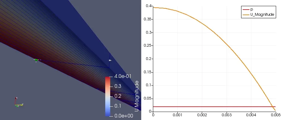
Below image indicates, included angle of 10 degrees and the corresponding pressure and velocity magnitude variation radially at 1.2 m from the entrance of the cylinder.
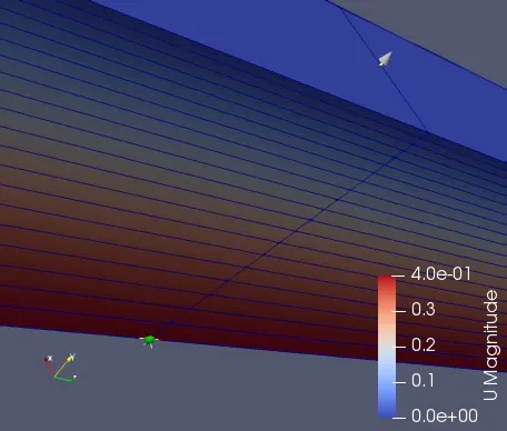
Below images indicates, included angle of 25 degrees and 45 degrees respectively.
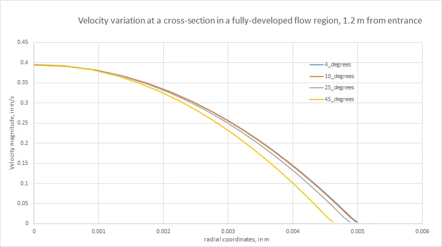
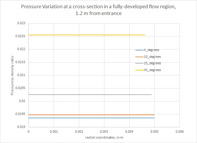
To know the behavior of the included angles for simulation, velocity and pressure variation as function of radial distance are plotted below:
Observations:
1. The above mentioned plot velocity variation as a function of radial coordinates at 1.2 m from entrance, clearly give an idea that fluid flow has achieved fully developed flow for all the cases. That is said by, central line velocity in each case is twice of the average velocity i.e 0.4 m/s fluid flow velocity at center of the pipe.
Note 1: Hydrodynamic entrance length =0.05*Reynold's number * Diameter of the pipe = 1m for this case. One more indication for fully developed flow is, central line velocity is two times mean velocity.
2. From the graph it is also clear that, as included angle increases velocity at which the fluid that becoming zero (i.e no slip condition) is achieved before the wall is reached. i.e as shown in below table,
| S.no. | included angle | Radial distance at which velocity becomes zero |
| 1 | 10 degrees | 0.00498 m |
| 2 | 25 degrees | 0.00488 m |
| 3 | 45 degrees | 0.004615 m |
3. It is also observed that when the velocity zero is achieved at a particular radial location, in successive the radial location steps pressure and velocity magnitudes are recorded as not a number. Which also says regarding the correctness of the simulation, as the included angle increases the correctness of the simulation is reducing as pressure and velocity magnitudes recorded as not a number. Even such pressure behavior can be seen in below graph, indicating the absence of many pressure magnitudes after a particular radial distance.Such a behavior is recorded and attached as a .xlsx file to this challenge.
4. Correctness of the simulation can only estimated by comparing analytical and simulation data in fully developed region for pressure slope variation. Now here, in the below plots indicate pressure variation along the length of the pipe for various included angles are shown. It is very clear that as the included angle increases, pressure slope in the fully developed region is increasing.
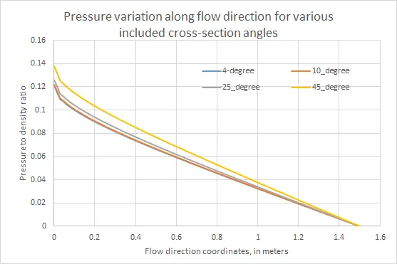
Here the slope for 4 degrees included angle case is shown below,
Note 2: Hagen Poiseuille's equation, `v=(-(\partialp)/(\partialx))((R^2-r^2)/(4\mu))`
From the above image pressure drop per unit length is slope of the curve, that is equal to `(P_1.3-P_1.2)/dx`
Where
- `P_1.3=19.3559 N/m^2`
- `P_1.2=12.8866 N/m^2`
- dx=0.1 m
Thus, the result for pressure gradient that is estimated using the graph results in `64.693 N/m^3`
In the Hagen poiseuille's equation,
Where,
- v is estimated for central line velocity which is 0.4 m/s
- R is 0.005 m (radius of the pipe)
- dynamic viscosity is `10^-3 m^5/(kg.s)`
- r is 0 as it is central line velocity
Thus, the result for pressure gradient that is estimated using the theory results in `64 N/m^3`
From above it is very clear that, numerical results for pressure gradient from the openfoam are in close agreement with theoretical results (i.e a considerable error of 0.693 `N/m^3`).
But when this included angle is further increased, the pressure gradient error gets increased tremendously which cannot be in fact approximated for a particular simulation.
Thus, on a final note for the results to be in close agreement with the case of the circular cylinder case the included angle for the simualtion to be very close or less than 5 degrees for increasing the correctness of the simulation and also decreasing the time of computation.