Week 12:Project 2-Meshing of Rear Wheel Holder challenge
Objective:
- To extract the mid surface and clean up the geometry on the given component.
- To generate mesh on the given component with low tria concentration and proper mesh flow.
- To assign the thickness for the given component.
INTRODUCTION:
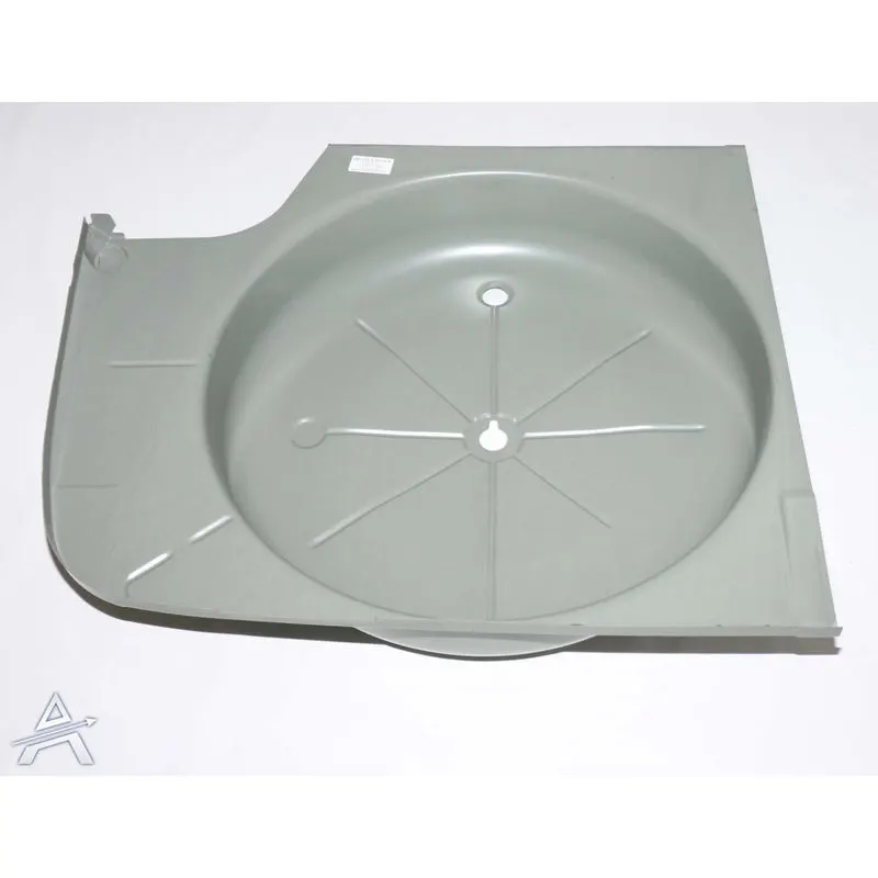
The model provided is a spare wheel floor panel for an automobile. This panel is manufactured using the stamping process where the raw material which is steel or aluminum sheet is introduced into the die and the hydraulic punch produces a punch so as to obtain the desired shape of the component.
PROCEDURE:
- The component is the floor panel of the car trunk, where we keep the spare tire.
- Since it is a sheet metal component it is of a uniform thickness.
- This component has a uniform thickness of about 0.75mm
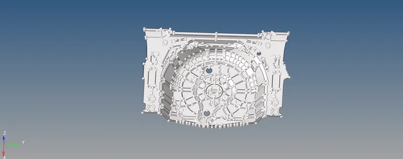
- Since this model is having a lot of complex converging areas and sharp edges, there might be an increase in the number of trias.
- Since the given file is in '.hm' format, we can directly open the file using the following steps.
- From the main bar, select FILE > click open > click model > select the file to open > click open.
Geometry cleanup
- After importing the model we can find out that there are many empty components and also some components are spread out in different components.
- We can organize them.
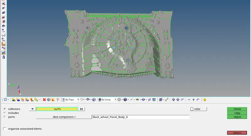
- First, move all the components to a single component using TOOLS>ORGANISE>COLLECTORS.
- Select surfaces and select all the surfaces to be moved.
- In the destination component, choose the component to which we have to move all these surfaces.
- Click on 'move'.
- After that, we can delete All the components using the delete option.
- From the above-showed option, choose components>preview empty.
- In the bottom left corner, we can see how many components are empty.
- Click on delete entity to delete those empty components.
- This model has no many deformations.
- There are only some unnecessary surfaces and some missing surfaces.
- To find out these errors easily, change the view to topo mode.

- We can use the mask option in order to check for the deformations in these areas.
- Select the mas tool visible on the side of the window or we can also use F5.
- Select the visible surfaces in order to mask them, so that the unnecessary inner surfaces can also be visible.
- Delete these surfaces and toggle the edge again by using Geometry>quick edit>toggle.
- Also in some areas, we can find some missing regions.
- These regions can be filled by using geometry>quick edit>filler surface and click on the edge of the surface to be filled.
- If it doesn't work, we can also go for the ruled option.Geometry>surface>ruled.
- Then select the two lines that require surface in between and then click on create
Midsurface extraction and its geometry cleanup
MIDSURFACING:
- Since this is a sheet metal component, it is of uniform thickness. We can also confirm this by checking the thickness of the various components.
- Checking thickness at the edges will be easy but checking thickness at the area except the sides is difficult. So we can do this using another tool.
- The option used in this project to extract the mid surface is "Offset+Planes+sweep.
Geometry clean up:
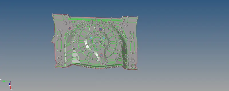
- After extracting the mid surface, some regions are noticed with surface deviation.
- These surfaces are cleaned by choosing a surface that is pretty much better than the other two surfaces
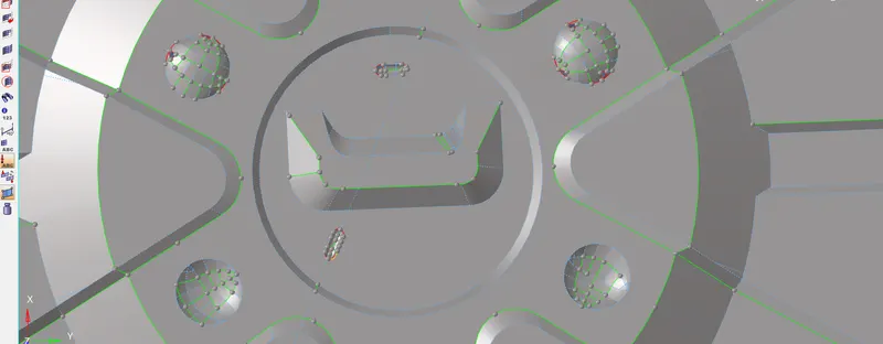
- The surfaces that are selected to be deleted
- Those deleted surfaces are re-created by duplicating and positioning the surfaces which are not deleted. The positioning is done by selecting the position option from the Tool panel .
- By selecting the surfaces, nodes that are to be positioned
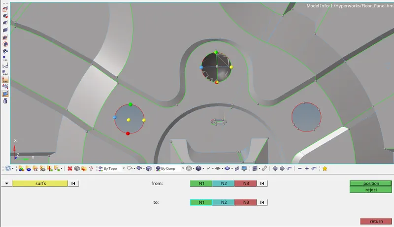
- The nodes from & to should be selected in the same direction. If selected improperly, the surfaces are not positioned properly.
- After positioning, the surfaces
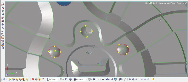
- The next step is to translate those surfaces, In order to fit the surfaces in that gap. The translate option is available in the Tool panel. The surfaces, vector direction & magnitude are entered.
- Similarly, the rest of the surfaces are positioned, translated if necessary, and toggled
- The next step is to delete the surfaces which are smaller in size. That results in the failure for minimum element size at the time of meshing.
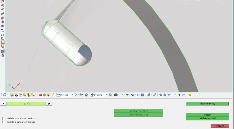
- The surfaces which are small in size are to be deleted
- The next step is to create the surfaces by using the option filler surface in the "Quick Edit" panel. After creating the surfaces in other regions if required.
Meshing:
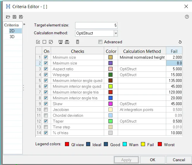
- Before meshing, the given quality criteria should be entered in the criteria editor
Target Element Length = 5 Units
| S.N | Quality Criteria | Value |
| 1 | Aspect Ratio | 5 |
| 2 | Skewness | 45 |
| 3 | Warping | 15 |
| 4 | Taper | 0.5 |
| 5 | Min. Length | 2 Units |
| 6 | Max. Length | 8 Units |
| 7 | Min angle Quad | 45 |
| 8 | Max angle Quad | 135 |
| 9 | Min angle Tria | 20 |
| 10 | Max angle Tria | 120 |
| 10 | Tria % | 10 |
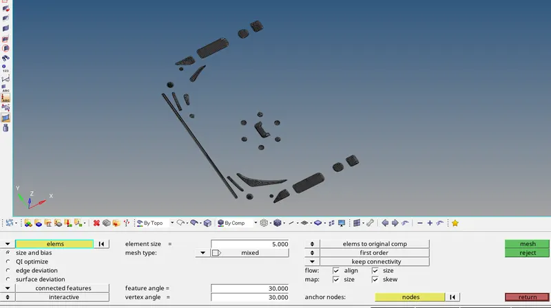
- The next step is to select all parameters like enabling align, size, element size, switching to elements to the current component

- Element to the surface component is chosen in order to add the mesh to the surface component.
- Keep connectivity is chosen in order for proper connectivity between the mesh.
- Align and Size options are ticked in order to get a good mesh flow.
- If the mesh is not that satisfying, we can change the Surface to Elements and select the required elements and click on the mesh option in order to mesh and get a more satisfying mesh.
- The mesh we get will have a lot of trias, fixed trias, and rotational quads. Also, the mesh flow won't be that good.
- In order to get a good mesh, we have to reduce the number of trias and also clear the rotational quads.
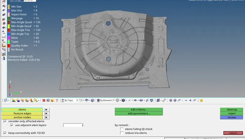
- This can be achieved by going to 2D>Quality index>Cleanup tools.
- We can reduce the trias and attain a good mesh flow by using the various cleanup tools.
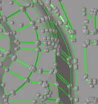
- The next step is to choose the complex region to mesh. In order to have control over the mesh flow and tria's. After selecting the surface, it is split in to sub surfaces
ELEMENT CLEANUP:
The main tools used in Quality index>Cleanup tools.
- Place node: Used to manually move the node.
- Smooth: Used to smooth the elements to get a good mesh flow.
- Swap edge: To swap the sides of the element.
- Node optimizes: Place the node in an optimized position which trias to reduce the errors.
- Element optimizes: optimize the element sides to eliminate errors.
- Split/Collapse edges: Used to split the elements.
- Drag tria elements: To move the trias in the mesh.
- Split quad elements: To split quad elements.
- Combine tria elements: Used to combine tria elements.
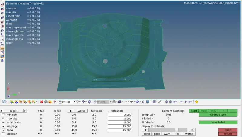
To check for free edges,
- To check for free edges we need to go to Tool>Edges.
- Choose Elements and then select the whole elements.
- Click on Find edges.
- Now Hide other parts and Make edges mesh only visible.
- Now check if there is the red line on any area which is not a boundary
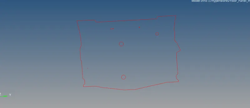
Assigning thickness
- After the whole meshing is done we can assign thickness to the mesh in order to make the 2d mesh exact as the real product.
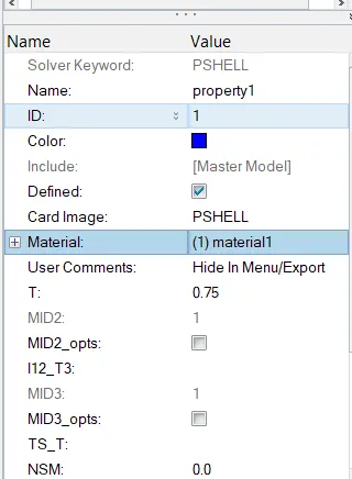
- This is a sheet metal model so the whole part will be having uniform thickness so we make a property and assign it to the component
- To make property. Right-click on Model view area > Create> Property.
- Rename the property with the thickness value.
- Also, set the thickness of the property. By clicking on the property we can see its details below.
- In that, we can see a T which represents the thickness give the thickness value. Click on enter.
- To Apply the property to the Components. Right-click on the component
- Select assign. Choose the property of the component from the pop-up dialogue box
- Click on Apply. Click on Ok.
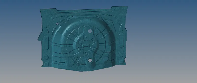
- To see the mesh in 3D. Choose the 2D detailed element representation.
FINAL MODEL:
Conclusion:
- Extracted the mid surface and performed the geometry clean-up on the given component.
- Generated the mesh on the given component with low tria concentration and proper mesh flow.
- Finally, assign the thickness for the given component.
Learning outcomes:
- Extracting the mid-surface.
- cleaning up the geometry.
- Generating the proper mesh flow.
- Reducing tria concentration.
- Assigning the thickness to the given component(Rear wheel holder).