Meshing of Rear Wheel Holder challenge
1. Objective:
- To extract the mid surface and clean up the geometry on the given component.
- To generate mesh on the given component with low tria concentration and proper mesh flow.
- To assign the thickness for the given component.
2 Extraction of Mid- surface:
During the mid surface extraction, The child component (i.e., component of mid surface) extracted should be an exact replica of the parent component.
The mid-surface extraction is done in two ways. They are :
- By using auto mid surface option
- By extracting manually
2.1.1 Extracting by auto mid surfacing:-
Generally, the extraction of mid surface by automatically is performed on "Sheet-metal" components. Because, those components will have uniform thickness. This option is seen in Geoemtry panel as shown in the below figure. This is done automatically in one shot by the algorithm of hyperworks software.

2.1.2 Extraction of mid surface manually:-
In general the extraction of mid surface manually is done on "plastic" components. Because, Those components will have varying thickness. This is done by checking the thickness, duplicating any one of the surface and offsetting it with the average of the thickness. This offset option is available in surface edit panel as shown in the below figure. Actually, it takes much time when compared to the auto mid surfacing.

3.1 Geoemtry clean up:
For any component, before meshing the geoemtry clean up should be done. This is done by performing "Topological repair" on it. At the time of geometry clean up, The errors like missing surfaces, Duplcate surfaces should be identified and clear them properly.
Topology repair consists of correcting connectivity errors between adjacent surfaces. The possible errors include :
- Unconnected adjacent surfaces.
- Duplicate surfaces.
- Missing surfaces.
The objective of topology repair is, to restore the surface data to a perfectly clean representation of the part. The process of topology is:
- To figure out what the ideal surface connectivity of the part should be.
- To Observe the current display of topology colors (free, shared, t-junction).
- Finally, To Use the tools in HyperMesh that get the connectivity from what it is to what it should be as quickly and efficiently as possible.
3.3 Meshing:
Meshing is done by using the "Auto mesh" option in 2D panel. And the key board short cut for it is F12. At the time of meshing, There should be a proper feature capturing & quality criteria should be maintained with proper tria management. Other important parameters in the tria managment are:
- There sholud me no trias in cornersor edges.
- No opposite trias.
- No back to back trias.
- No trias in fillets or Hemmings(Mininimal).
- No rotational quads.
- No trias should share a boundary with a feature line.
- There should be a proper connectivity between elements.
- At the time of meshing, Its better to Split and perform mesh.
- Mixed type mesh should be used for irreglar shaped surfaces and quads are used only for rectangular/square surfaces(Oppoosite sides should be parllel and equal).
Finally after meshing, the following checks should be done:
- Qualty criteria
- Free edges (Keyboard short-cut is Shift+F3).
- Normals (Process for selecting normals option is Tool---> Normals).
After checking all these, The thickness is assigned to the component. This is done by right clicking on tab bar and creating a property at the tab bar which appears as a tree in the left side of the display as shown in the below figure.
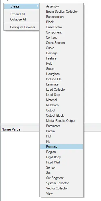
After creating a property, by clicking on the property. The parameters with respect to that property are shown at the bottom. In that one of the parameter is thickness is "T". The required thickness value is entered in it.
4. Procedure:
4.1 Extraction of midsurface:
Initally the given geometry is imported in to the hyperworks. After importing, the given component appears as shown in the fig 4.1.1.
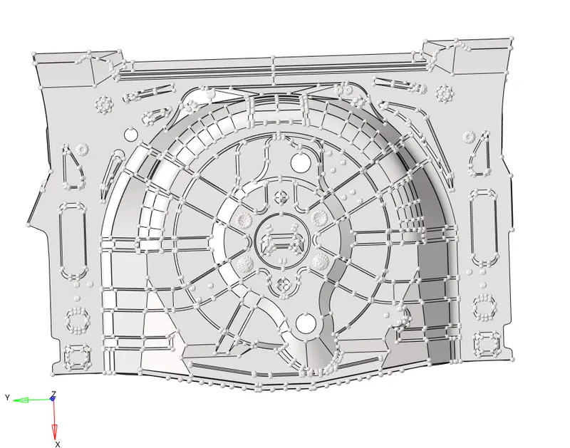
fig 4.1.1
The next step is to view the given component "By Topo". By enabling the topo mode, the given component appears in the graphical display as shown in the fig 4.1.2.
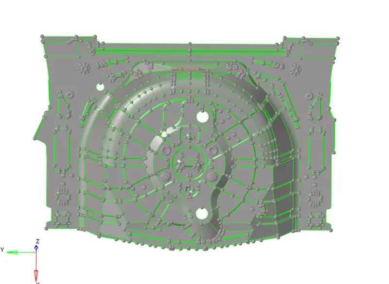
fig 4.1.2
The next step is to extract the mid surface. As the given component is made up of material named "Sheet metal", it will have the same thicknesses in most of the cases. So, The midsurface can be extracted automaically. This is done by selecting the mid surface option from the geometry panel as shown in the fig 4.1.3. 
fig 4.1.3
The option used in this project to extract the mid surface is "Offset+Planes+sweep". The extracted mid surface appears in the graphical display as shown in the fig 4.1.4.
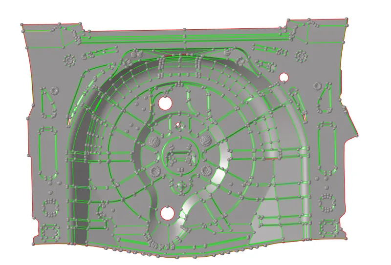
fig 4.1.4
4.2 Geometry clean up:
After extracting the mid surface, some regions are noticed with surface deviation as shown in the fig 4.2.1. These are to be cleaned by using geometry clean tools.
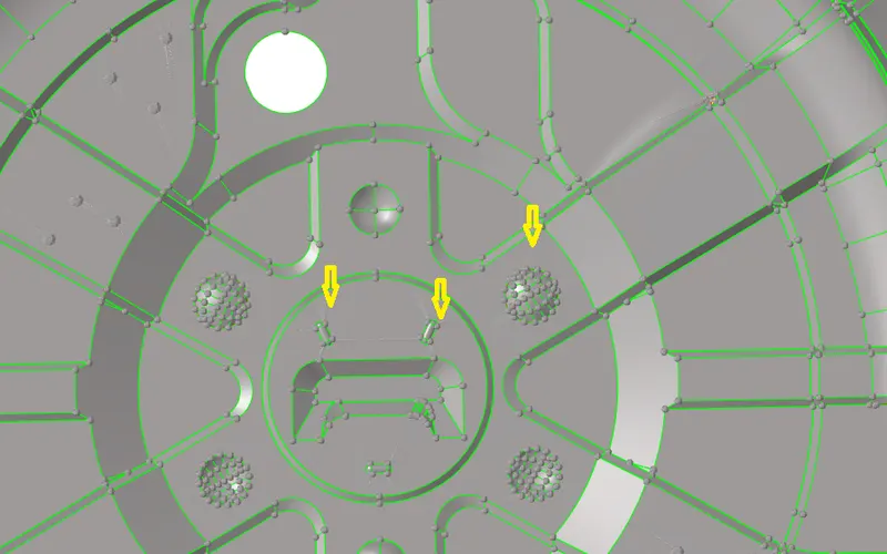
fig 4.2.1
These surfaces are cleaned by choosing a surface that is pretty much better than the other two surfaces. And, There are three surfaces which are raised as shown in the fig 4.2.2. And the remaining three surfaces are lowered with respect to the base surface as shown in fig 4.2.3.
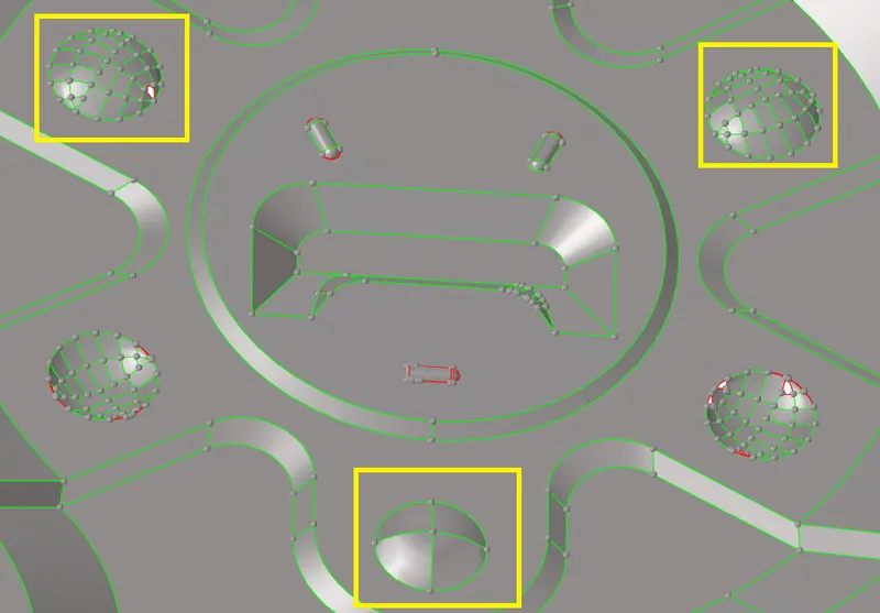
fig 4.2.2
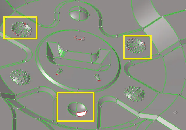
fig 4.2.3
The surfaces that are selected to be deleted are shown in the fig 4.2.4.
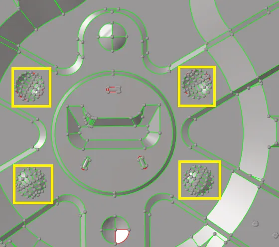
fig 4.2.4
After deleting those surfaces, those regions appears as shown in the fig 4.2.5.
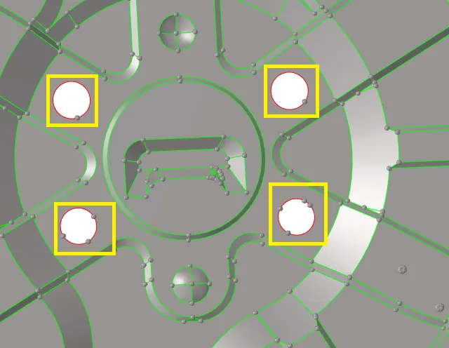
fig 4.2.5
Those deleted surfaces are re-created by duplicating and posistioning the surfaces which are not deleted. The positioning is done by selecting the position option from Tool panel as shown in the fig 4.2.6.

fig 4.2.6
By selecting the surfaces, nodes that are to be positioned. It appears as shown in the fig 4.2.7.
Note: The nodes from & to should be selected in the same direction. If selected improperly, the surfaces are not positioned properly.
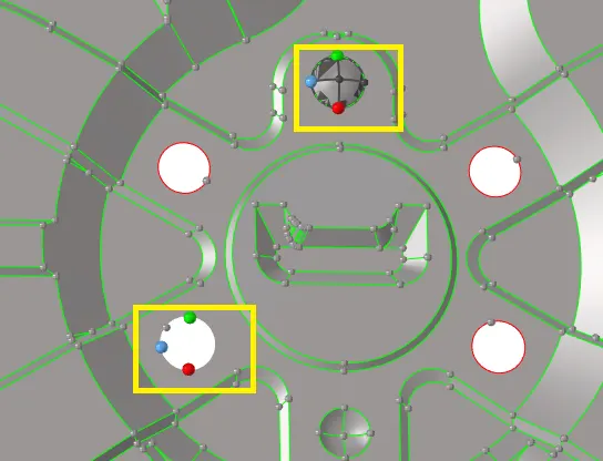
fig 4.2.7
After postioning, the surfaces appears as shown in the fig 4.2.8.
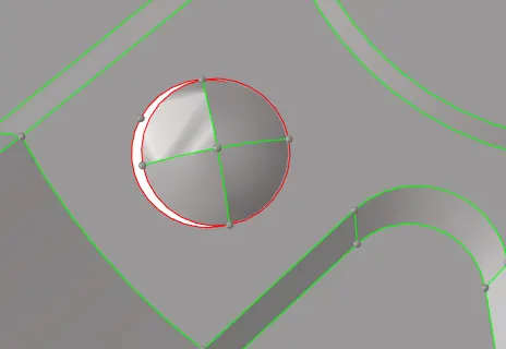
fig 4.2.8
The next step is to translate those surfaces, In order to fit the surfaces in that gap. The translate option is available in Tool panel. The surfaces, vector direction & magnitude are entered as shown in the fig 4.2.9.
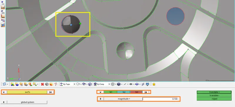
fig 4.2.9
Similarly the rest of the surfaces are positioned, translated if necesscary and toggled. After doing all these things, the surfaces at that region appears as shownn in the fig 4.2.10.
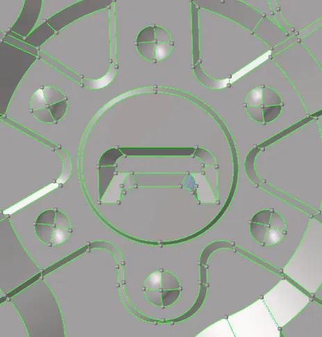
fig 4.2.10
The next step is to delete the surfaces as shown in the fig 4.2.11, which are smaller in size. That results in the failure for minimum element size at the time of meshing.
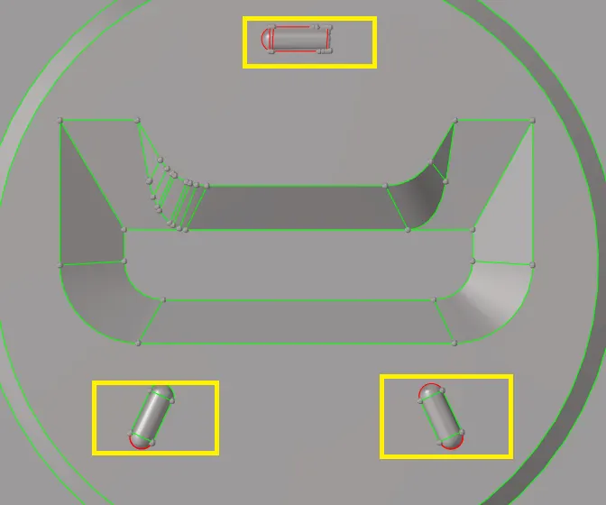
fig 4.2.11
After deleting the surfaces, the and creating the surfaces are re-created by filler surface as shown in the fig 4.2.12.
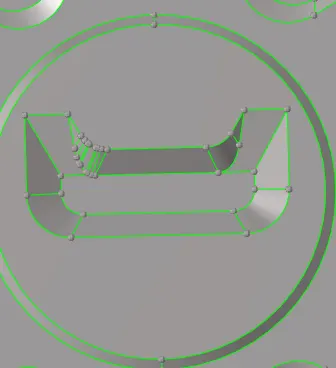
fig 4.2.12
The surfaces which are small in size are to be deleted as shown in the fig 4.2.13.
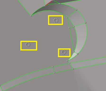
fig 4.2.13
After deleting those surfaces, that region appears as shown in the fig 4.2.14.
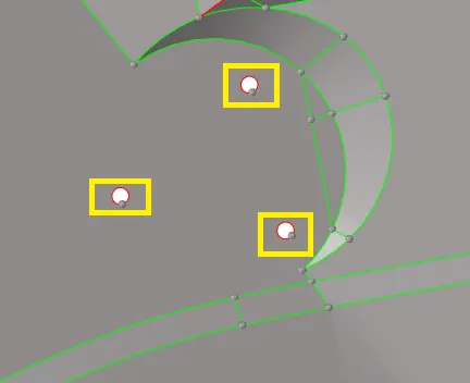
fig 4.2.14
The next step is to create the surfaces by using the option filler surface in "Quick edit" panel. After creating the surfaces in those regions. That region appears as shown in fig 4.2.15.
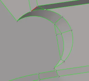
fig 4.2.15
Some surfaces are small in distance, Which results in failure of minimum eleemnt size at the time of meshing. To overcome this problem, a mid line is created the middle of the surface as shown in the fig 4.2.16. The process of creating the mid line is Geometry---> Lines---> Mid lines.
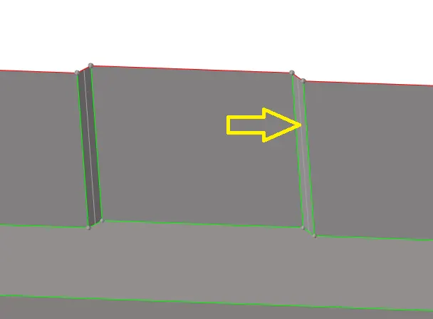
fig 4.2.16
This surfaces are trimmed with respect to lines With the (Trim with lines) option in surface edit panel. And after trimming the surface is didvided in to two parts. Then the created mid line is deleted. And the two lines near to the newly created mid line are toggled. Similarly, all the un-wanted edges are toggled.
After doing the geoemtry clean up, the given component appears as shown in the fig 4.2.17.
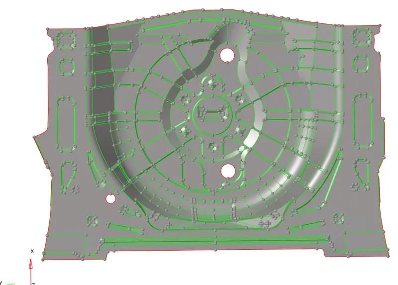
fig 4.2.17
4.3 Meshing:
Before meshing, the given quality criteria should be entered in the criteria editor as shown in the fig 4.3.1. The process of selecting this criteria editor is: Prefernces ( In Menu bar)---> Criteria File settings.
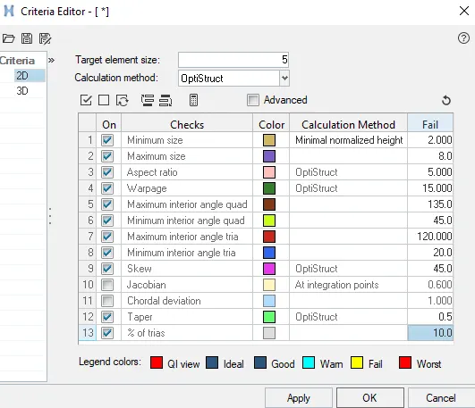
fig 4.3.1
The next step is to select all parameters like enabling align, size, element size, switching to elements to current component as shown in fig 4.3.2. 
fig 4.3.2
The next step is to choose the complex region to mesh. Inorder to have the control over the mesh flow and tria's. After selecting the surface, it is splitted in to sub surfaces as shown in the fig 4.3.3. Which results in reucing the tria's at that region.
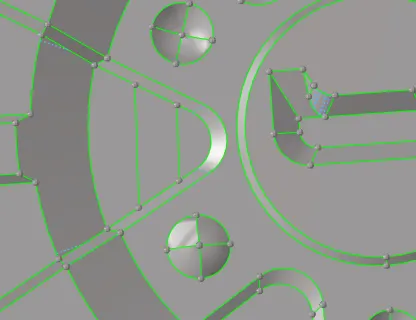
fig 4.3.3
And then meshing is done. After meshing, the splitted surfaces are to be unsplitted by enabling the option "Keep mesh", Inorder to not disturb the mesh at the time of unsplitting. After doing all these, the mesh at that region appears as shown in fig 4.3.4.
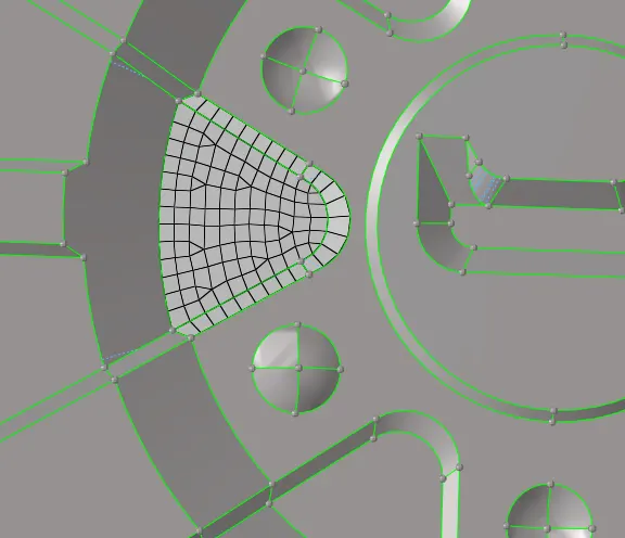
fig 4.3.4
Similarly, all the surfaces are meshed by splitting. After generating the mesh, the given component appears as shown in fig 4.3.5.
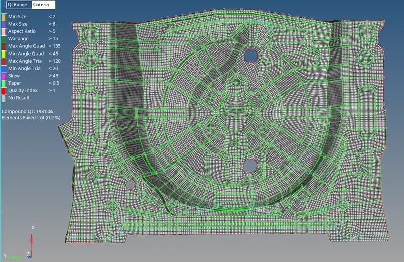
fig 4.3.5
The next step is to concentrate on rectifying the errors. If noticed in the fig 4.3.5, there are 74 elements failing for the quality criteria. Some of the errors represented in various colours are shoen in fig 4.3.6.
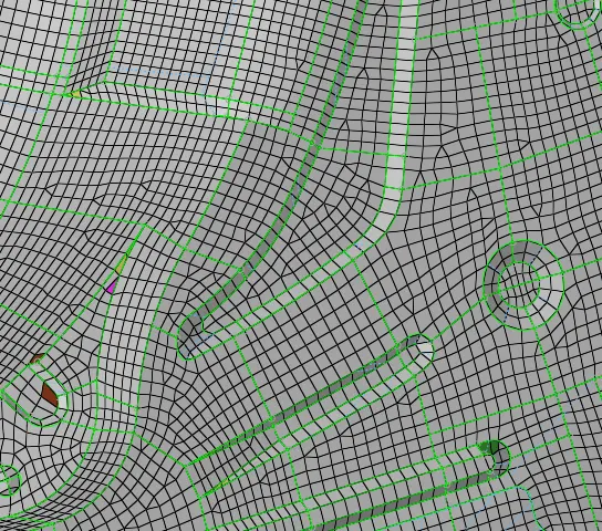
fig 4.3.6
Note: Before going to rectify the errors, Free edges are to be verified first. Because, there may be a chance of forming errors regarding quality criteria again.
So, The free edges are to be verified now. Only if there is no free edges inside the component as shown in fig 4.3.7, the errors regarding quality criteria are rectified.
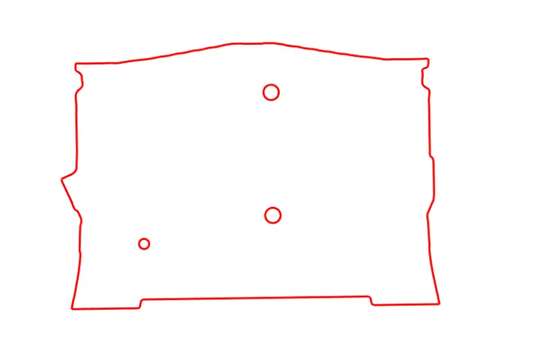
fig 4.3.7
These errors regarding the quality of elements are rectified by the Option named "quality index" in 2D panel. After rectifying those errors, the component with zero errors is shown in fig 4.3.8.
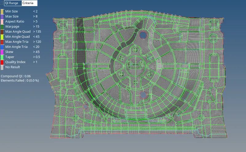
fig 4.3.8
The next step is to reduce the tria %. The achieved tria % is 2.3, which is shown in the fig 4.3.9.
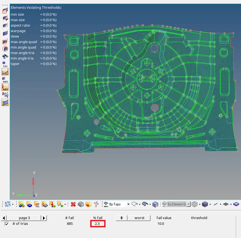
fig 4.3.9
The next step is to check for normals. Normals indicates the direction through which force travels, when it is applied. The normals can be viewed in two ways. They are:
- By color display
- By vector display.
Both are same, But the way of representing the normals are different. The color display, represents the normals in the form of two colors. One is "Red" in colour, Which indicates the positive normal direction Which appears as shown in fig 4.3.10. And in the back side of this consists of "Blue" colour, which indicate the negative normal direction as shown in fig 4.3.11. Whereas, coming to the vector display, the elements are represented with the vector direction as an arrow.
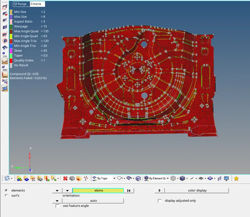
fig 4.3.10
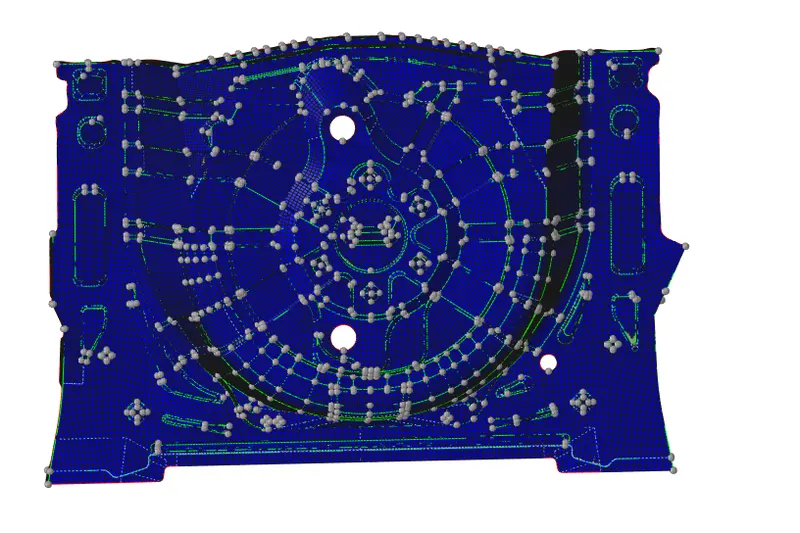
fig 4.3.11
4.4 Assigning Thickness:
The next step is to assign the thickness. For doing this, a property should be created. A property can be created by right clicking on the tab bar, a pop-up appears as shown in the fig 4.4.1. Which indicates the "Create " Option.
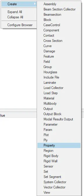
fig 4.4.1
After creating the property, for easy understanding the name of the property is renamed. And kept it as on the name of the thickness, as shown in the fig 4.4.2.
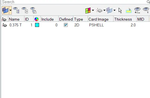
fig 4.4.2
After renaming it, the thickness value is given to the property by clicking on the name of the property in the tab bar. A dialogue box at the bottom left corner appears as shown in the fig 4.4.3. The thickness value measued from the parent geometry is entered at the thickness parameter.
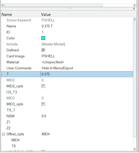
fig 4.4.3
After entering the thickness value to the component, The next step is to assign the property to the component. This is done by right-clicking on the component in the tab bar, Which shows the option to assign as shown in fig 4.4.4.
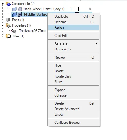
fig 4.4.4
After clicking on assign, a pop-up appears as shown in fig 4.4.5. In which the created property is selected. And then click on "Apply" & "Ok".
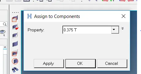
fig 4.4.5
The component visualizing "By Property" with the assigned color appears as shown in fig 4.4.7.
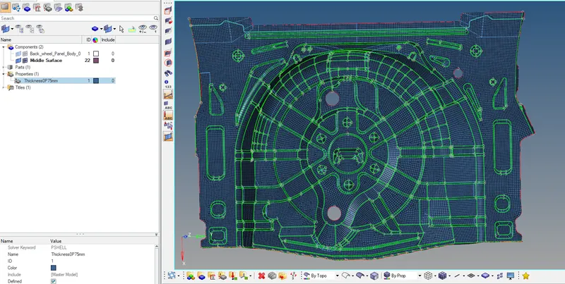
fig 4.4.7
The final component after meshing, assigning thickness is shown in fig 4.4.8.
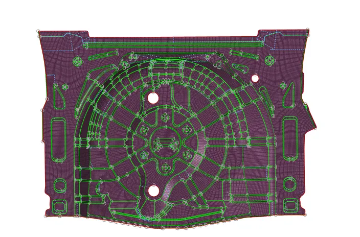
fig 4.4.8
5. Conclusion:
- Extracted the mid surface and performed the geometry clean-up on the given component.
- Generated the mesh on the given component with low tria concentration and proper mesh flow.
- Finally, assign the thickness for the given component.
6. Learning outcomes:
By doing this project, the following aspects can be learned:
- Extracting the mid surface.
- cleaning up the geometry.
- Generating the proper mesh flow.
- Reducing tria concentration.
- Assigning the thickness to the given component(Rear whee