Week 12:Project 2-Meshing of Rear Wheel Holder challenge
OBJECTIVE:-To create midsurface and Meshing of Rear Wheel Holder with the below quality parameters and generated mesh should have low tria concentration and proper mesh flow.
Target Element Length = 5 Units
| S.N | Quality Criteria | Value |
| 1 | Aspect Ratio | 5 |
| 2 | Skewness | 45 |
| 3 | Warping | 15 |
| 4 | Taper | 0.5 |
| 5 | Min. Length | 2 Units |
| 6 | Max. Length | 8 Units |
| 7 | Min angle Quad | 45 |
| 8 | Max angle Quad | 135 |
| 9 | Min angle Tria | 20 |
| 10 | Max angle Tria | 120 |
| 10 | Tria % | 10 |
CAD MODEL IMAGE:-
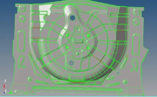
Fig 1 CAD image
PROCEDURE:-
1.Import the file into hypermesh -select→import→import model.
2.Click on the files select model and click on import.
3. Geometry Cleanup
Before extracting the mid surface from the model, ensure that the model surface is perfect and free from errors like free edges, duplicate surfaces and missing surfaces. If any defects are found then the required geometry cleanup needs to be done using the various tools such as toggle edge, filler surf, replace points etc. available under the quick edit panel. (F11 (or) Geom>quick edit)
By closely inspecting the model, various defects in the surface geometry such as free edges (indicated by red lines) and duplicate surfaces (shared edges indicated by yellow lines) can be easily found out and rectified.
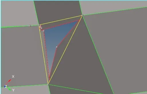
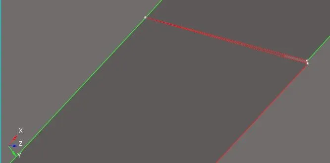
Fig 2 Surface defects before
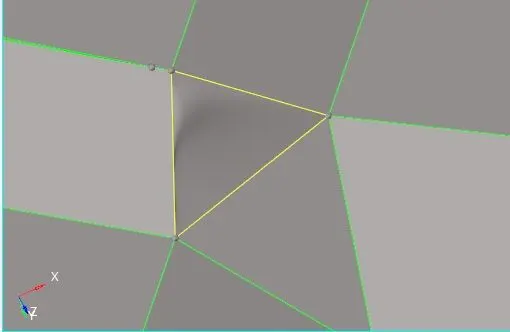
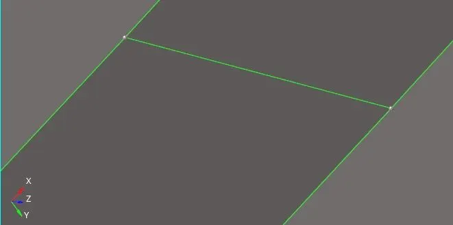
Fig 3 Surface defects after
Using the offset tool the outer surface of the floor panel is offset by a distance that is equal to half of, the distance measured between the outer and inner surfaces of the floor panel. (0.75/2 = 0.375mm )
(Geom>surface edit>offset>select 'surfs'>specify offset distance>offset)
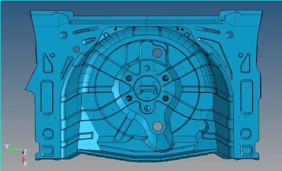
Fig 4 Extracted Mid surface
After extracting the midsurface any defects on the extracted midsurface is rectified before starting the process of meshing. Also, for ensuring proper mesh flow and also for ease of meshing the surface is divided into sections and the meshing is carried out on each of the sections one by one.
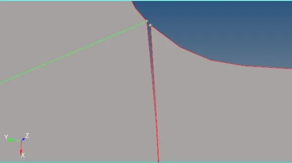
Fig 5 Mid surface Cleanup before
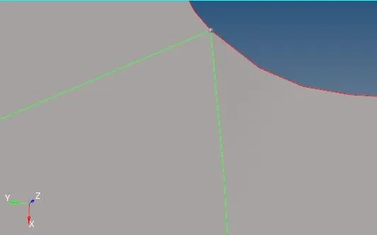
Fig 6 Mid surface Cleanup after
The mentioned quality criterias need to be specified using the criteria file editor before meshing the model.
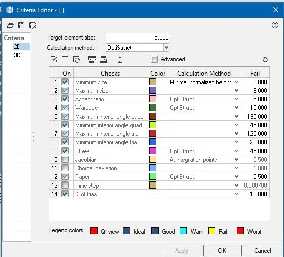
Fig 7 Criteria file
The generated mesh is examined properly to ensure that there is a proper mesh flow. Also, the number of trias should be kept to a minimum. Ensure that there are no rotating quads, back to back trias, opposite trias or trias on feature line.
Check if any elements are failing for any of the given quality criterias. If any element is found to be failing the given quality criteria then the cleanup tools are used to correct them.
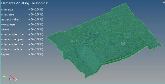
Fig 8 Quality Check
Mesh should also be checked for any imperfection or disconnected mesh. For that we can use find edge command.
TOOL --> EDGE --> FIND EDGES


Fig 9 Edge check command
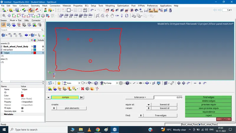
Fig 10 Edges found in the model
Assigning thickness
After meshing, the elements have to be assigned the measured thickness of the floor panel. For this, a ‘property’ has to be created. (Right click tab area>create>property)
Under the property menu the thickness ‘T’ has to be specified. Also, other properties like the material and card image can also be specified if needed.
To assign the property to the component, right click on the corresponding component and choose the ‘assign’ option. In the pop up menu select the corresponding property from the drop down list and apply.
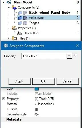
Fig 10 Assigning thickness
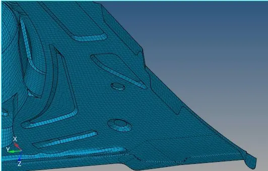
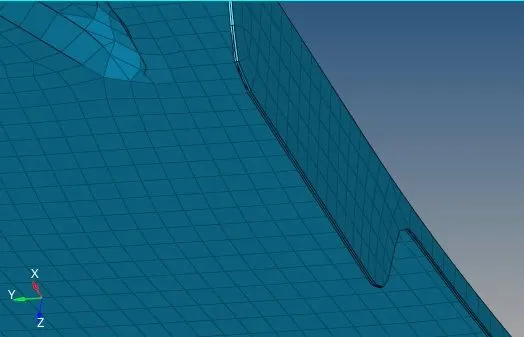
Fig 11 Assigning thickness before and after
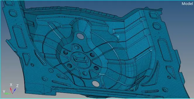
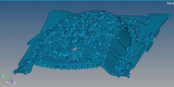
Fig 12 Final mesh images
Result:-
Midsurface generated corrected and meshed successfully for the the given CAD geometry with zero elements failing and low tria concentration.