Week 12:Project 2-Meshing of Rear Wheel Holder challenge
#14 // Week 12: Project 2-Meshing of Rear Wheel Holder challenge.
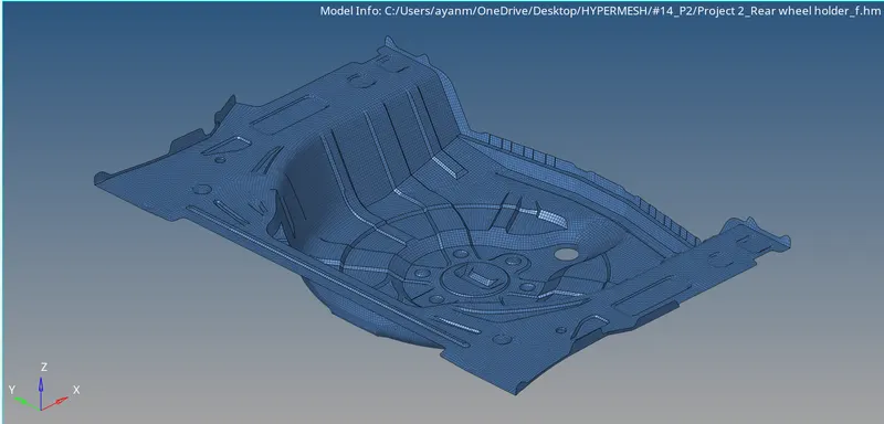
AIM: To mesh the rear wheel holder of a car following the element quality criteria given.
OBJECTIVE:
- To generate the mid surface manually and do a geometry clean up on the component.
- To generate a mesh and to get a proper mesh flow on the given component with low tria concentration.
- To check the elements quality according to the given quality criteria.
- To assign a thickness for the component.
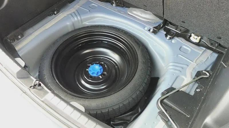
Introduction : The component given to us is car stepney spare wheel floor panel. This component is a sheet metal component. For the plastic and Sheetmetal component with the thickness less than 6mm,We have to take a mid-surface and then we have to mesh. Sheet metal is metal formed by an industrial process into thin, flat pieces.
PROCEDURE:
- Import the model.
- importing the file given in any one of the formats. The option to import the file varies according to the file format and the file format given here is IGES, the file is imported under geometry file option.
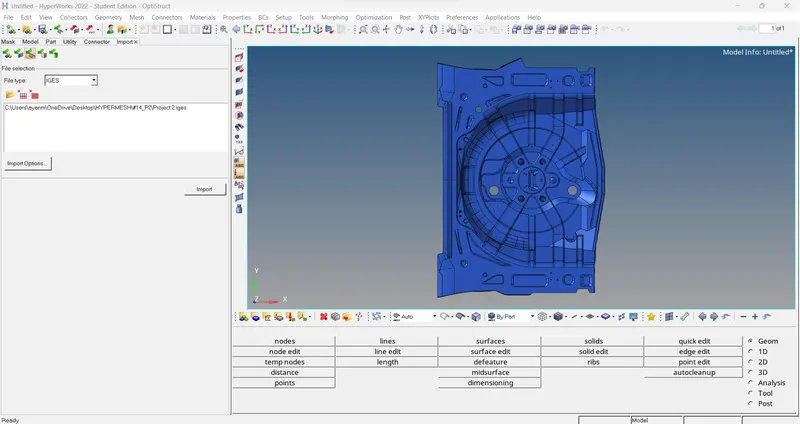
- After importing, the geometry color mode is changed from auto to by topo mode and the surface/solid is visible. If any solid is found it is recommended to delete solid part.
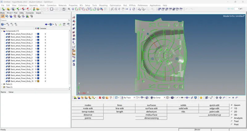
- The parent component itself damage a lot, but we can directly go for Geom > midsurface (auto) option & extract the mid surface, fix the geometrical issue in it.
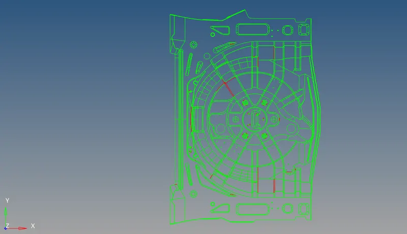
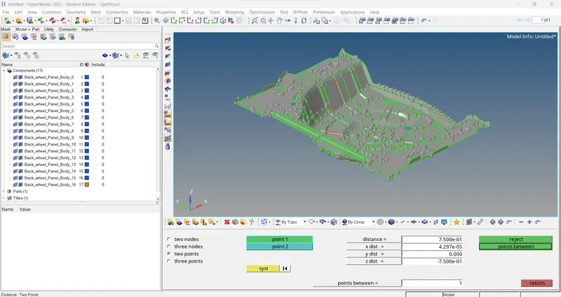
- Or we can measure the thickness in parent component using Geom > distance option and check the thickness. Then go Geom > surface edit > offset & extract mid surface manually.
- The thickness here is almost uniform of 0.75mm.
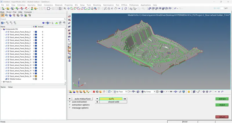
2.Extract the Midsurface.
- To extract the mid surface, go to Geom > midsurface > Extraction option - offset(auto) select the surface (displayed) > extract.
3.Geometry Clean-up.
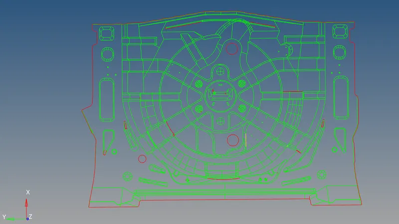
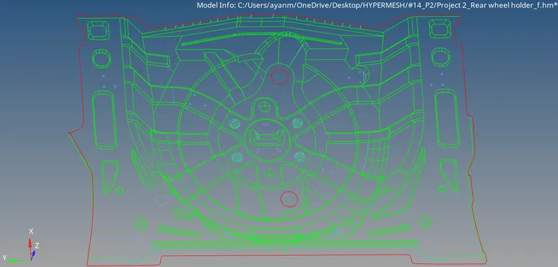
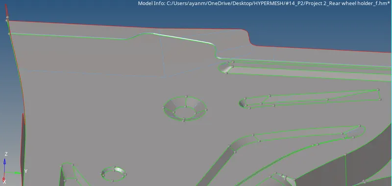
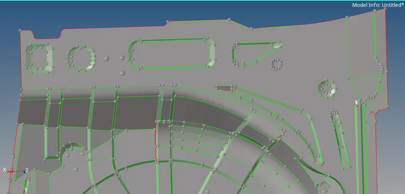
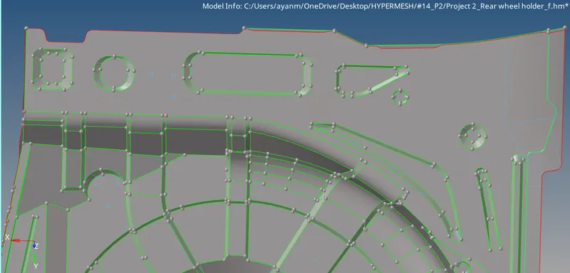
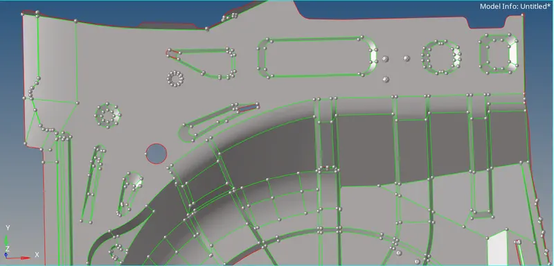
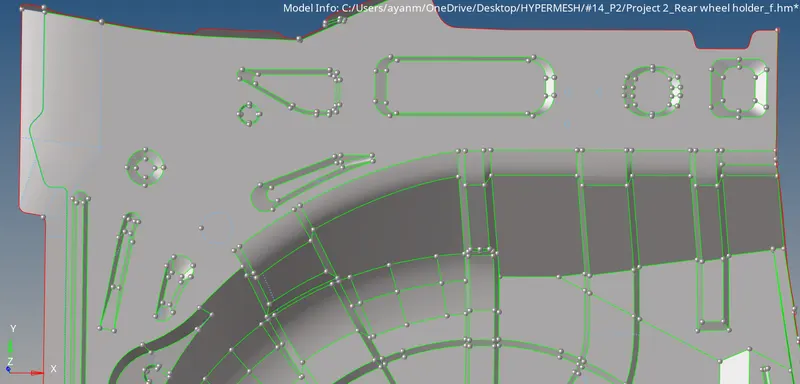
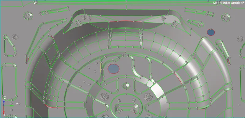
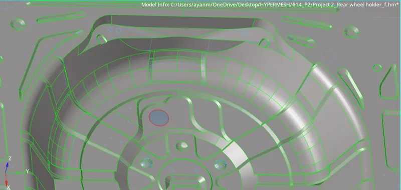
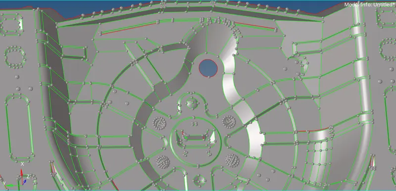
- Some of the region in the face of Rear Wheel Holder will be distorted exp. misaligned lines, unchecked faces, damaged faces, non-washers face, etc.
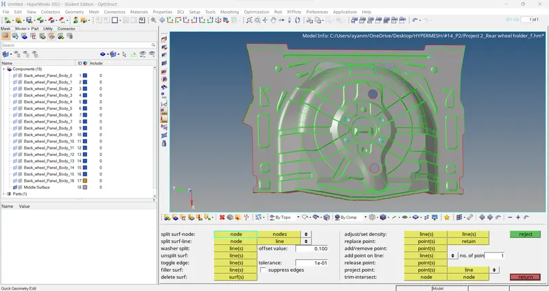
- To fix the geometrical errors go to Geom > quick edit (F11) > split surf-node / split surf-line / toggle edge / filler surf / replace point / add or remove point
- And also for missing surface go to Geom > surface > ruled option > create.
// Note: -
> Brief of quick edit panel-
i) Geometry > Quick edit > split surface node….
- Select two locations of the nodes to split the surface and then select an additional node to continue to split the surface.
ii) Geometry > Quick edit > Split surf-line….
- In this, select a node and select a line to split the surface, here the split will be perpendicular to the line chosen.
iii) Geometry > Quick edit > Adjust/set density….
- After meshing a particular surface. We can adjust the mesh density by using this tool. While meshing we will increase the nodes to get a proper mesh flow. We can also increase nodes after meshing by using this tool.
iv) Geometry > Quick edit > Release points….
- Drag and select the surface, where you want release the points. After releasing the points. The free edges will exist.
v) Geometry > Quick edit > Replace points….
- Move points from their current locations to the locations of other points, where we want them to replace it.
vi) Geometry > Quick edit > Add/Remove points….
- Use window selection (with the left mouse button and right mouse button) to add and remove any points within the
selection box.
vii) Geometry > Quick edit > Add points on line….
- Specify the number of points that we wish to add to that line, and then select the desired line in our model.
viii) Geometry > Quick edit > Delete surface….
- Select the surface which we need to eliminate and delete it.
//
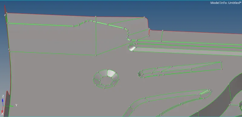
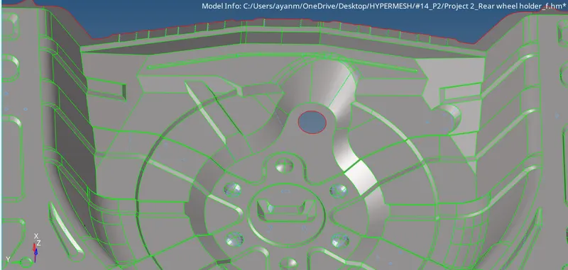
> some shots of geometry clean-up & Defeaturing..
>> Before.... >> After....
4. Meshing.
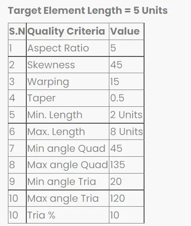
- Before applying mesh, we need to set up given quality criteria as per specified to create quality mesh and also about meshing parameter for every particular Rear Wheel Holder model parts.
- Go to option panel > preferences > parameter file settings/ criteria file settings > set it as per given.
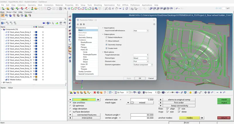
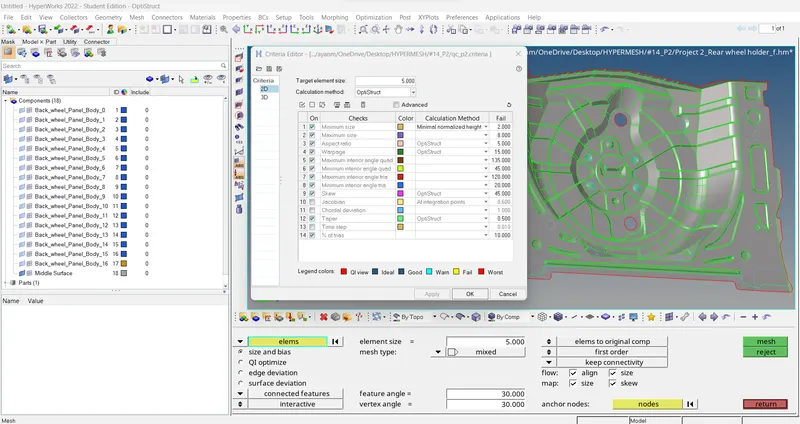
- After the Quality criteria are set, we then need to proceed to mesh the midface. To perform meshing on the component, we need to use the command of Automesh (F12) under the 2D Tab. In this command, we need to change the element type to "Mixed" and change the average element length to 5mm (as given in the Quality criteria). Always keep the flow Align and size option ticked as it will give a much better mesh flow on the component. The basic rules while meshing is to be followed here, such as that there should be no tria element on a feature line and even avoid the rotational Quad elements in the mesh. We also need to keep the tria count as low as possible because Tria elements are much stiffer than Quad Elements, but Tria elements are to be given preference over the presence of Rotational Quad Elements. If we get any Fixed/Pattern Tria we simply need to remesh these regions. Or we can simply resolve the Rotational Quad elements into two separate tria elements in two different directions or even resolve the Fixed/pattern tria elements into three different directions as well.
- These elements need to be cleaned to get the requirement mesh criteria.
- The failed elements can be fixed using the element fixing tools in the quality criteria menu.
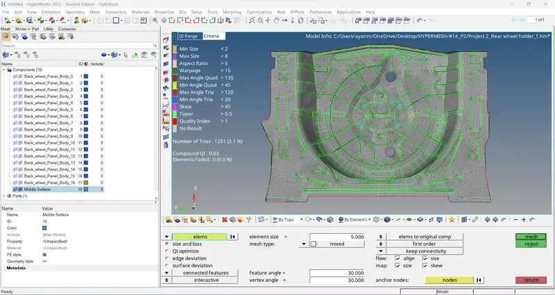
> To check the elements quality according to the given quality criteria.
- There are even some other tips to be followed during meshing such as avoiding trias as much as possible, eliminating rotational quads, avoiding high element density, eliminating trias on the free edge or feature edges and so on.
- To make the mesh flow proper the element clean-up tools in the quality index are used and the smoothening of the elements are meshing is more important to get a uniform mesh flow.
- And in some regions make some splits & restrict the curvature region, then remesh / rebuild both to get a proper mesh flow.
- If possible try to move trias & off elements in plane regions and then remesh / rebuild that region to fix it.
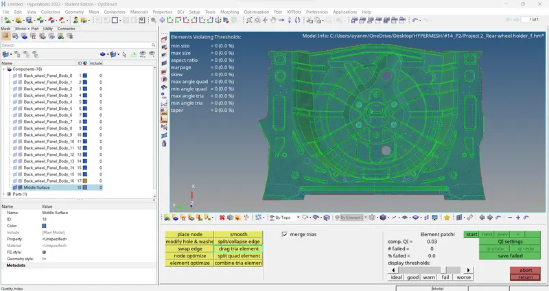
// Note: In this model here, i have two option either i go with clear all off elements & compromise a bit with the feature region Or i choose to feature capturing & ignore few off elements nearby of it. So, i choose to go with clear off elements & do some correction in feature region.
- Go to 2D > replace (F3) Or Tool > Translate (shift+F4) to clear off elements in that feature region.
//
5. Assign thickness:
- Soon after the complete meshing of the component is done, assigning thickness to the elements in the component is carried out. The thickness of the component is measured and the thickness value (for this model 0.75mm) is fed in the property panel of the respective component collector. The property collector is then assigned to the component and thus the thickness is visible in the window by enabling the 2D Detailed Element Representation.
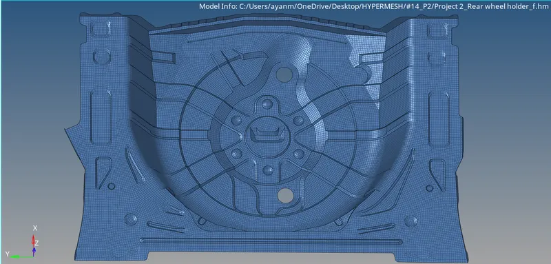
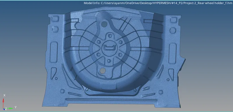
- Thus, the given component is meshed under the given quality criteria and assigned thickness.
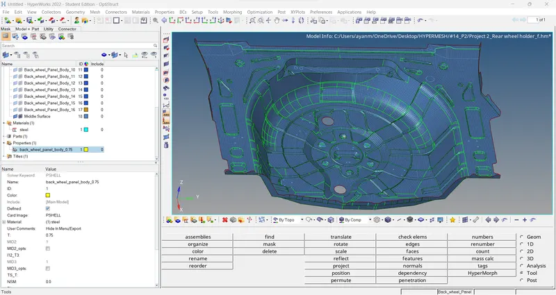
> 2D DETAILED ELEMENT REPRESENTATIONs:
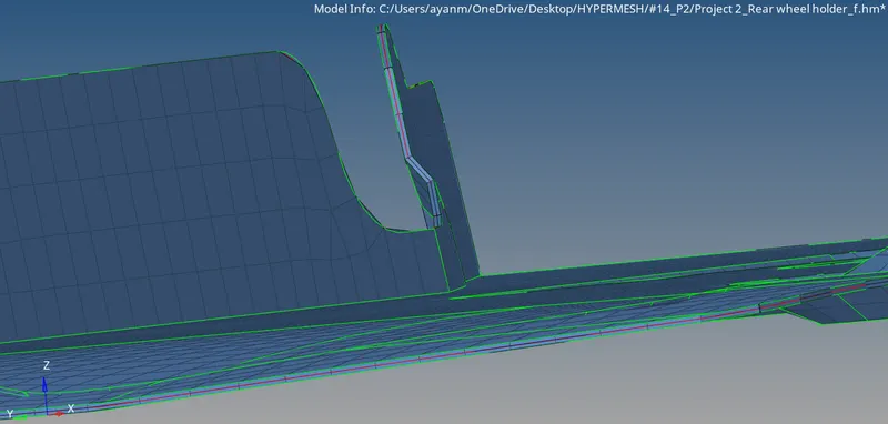
-- Final checks >>
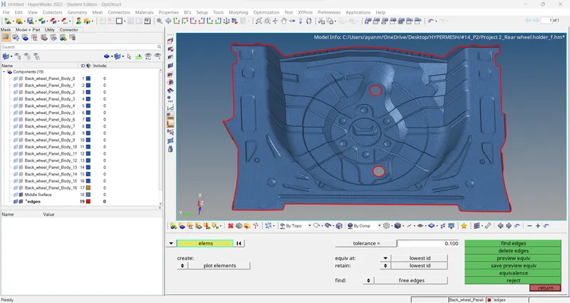
- EDGES check >
Edges check is done to ensure the connectivity of the elements is present.
Go to Tool > edges > elements(displayed) > find edges.
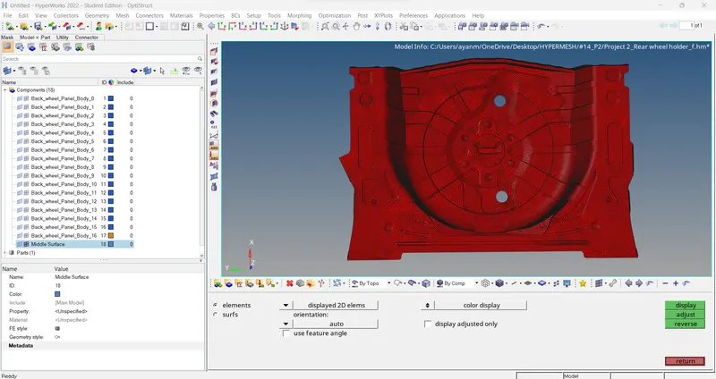
- Normal check >
Normal check is performed to check the direction of the vector consistency of the geometry/Elements which directly affect the calculation of the physical quantity.
Go to Tool > normals > display. (adjust)
- Duplicate check >
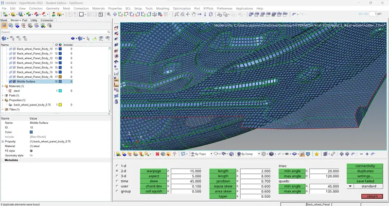
To check any duplicate elements are present in the model.
To do that tools panel shrink elements & analysis manually if there any duplicate elements present.
Or else, go to Tool > elem check > duplicates, here we analysis if there any duplicates elements.
RESULTS-
Final View of model: -
Learning Outcome and Conclusion -
- In this project, I came to know
- How to mesh a complex Sheetmetal component.
- How to extract the mid surface manually for the complex Sheetmetal components.
- How to clean complex geometry.
- How to generate a proper mesh flow with low tria percentage.
- How to assign thickness to the components.
CONCLUSIONs:
Therefore, the given model is meshed under the given quality criteria and assigned thickness successfully.