Week 12:Project 2-Meshing of Rear Wheel Holder challenge
AIM:
To perform FE modelling of an Automotive Spare wheel holder - Stamped sheet metal component by considering the given element Quality criteria.
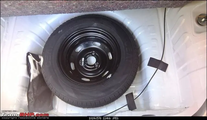
Automotive Spare wheel holder panel
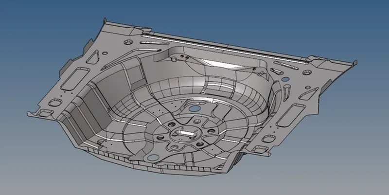
CAD MODEL: Here the given cad model is Automotive Spare wheel holder - Stamped sheet metal component.
QUALITY CRITERIA :
Every product which is been produced will go through the set of quality check. If the quality check fails other steps like boundry condition & loads assignment will not be feasible, So for this reason the element quality check is performed. To identify the quality failure the quality criteria will be entered as an input data. The given quality criteria are shown in the below table. The elements should be maintained within the below given value. If the given quality value is not maintained there will be a failing in qulaity.
|
S.NO |
QUALITY CRITERIA |
VALUE |
|
1. |
Target/Avg length |
5 |
|
2. |
Min. length |
2 |
|
3. |
Max. length |
8 |
|
4. |
Aspect ratio |
5 |
|
5. |
Warpage |
15 |
|
6. |
Skewness |
45 |
|
7. |
Taper |
0.5 |
|
8. |
Min. quad angle |
45 |
|
9. |
Max. quad angle |
135 |
|
10. |
Min. Tria angle |
20 |
|
11. |
Max. Tria angle |
120 |
|
12. |
Tria percentage |
10 |
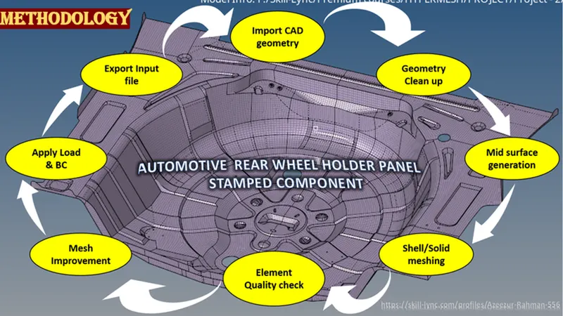
METHODOLOGY:
Import CAD geometry.
Geometry cleanup.
Mid surface / Skin generation.
Shell or solid meshing.
Element quality check.
Mesh improvement.
Apply load & Boundry condition.
Export input file.
- Import CAD geometry:
Input the given cad model. Here the given cad model is Automotive side door inner panel - Trim component.
Also enter the input values - The given quality criteria value.
- Geometry cleanup:
To generate FEM we clean up the geometry.
Surface patch up, creating new surfaces, eleminating of triple cons in unwanted area, converting single cons to double cons in necessary area are comes under geometry cleanup phase.
The rear wheel holder is a plastic component and it has a uniform thickess in it and then the model is cleaned. The cleaning process consists of
closing the holes below 3mm,
toggeling the unwanted lines in the surfaces,
defeaturing the small dia fillet areas,
splitting the surfaces into parts,
filling the empty surfaces,
add/remove the points in the lines,
delete the unwanted surfaces.
There are many useful tools present in the Hypermesh to aviod errors in the model during meshing. The main tool we used in the model is Geometry--->quick edit. The shortcut used for the quick edit tab is F11 key from the keyboard.

Split surf-node:
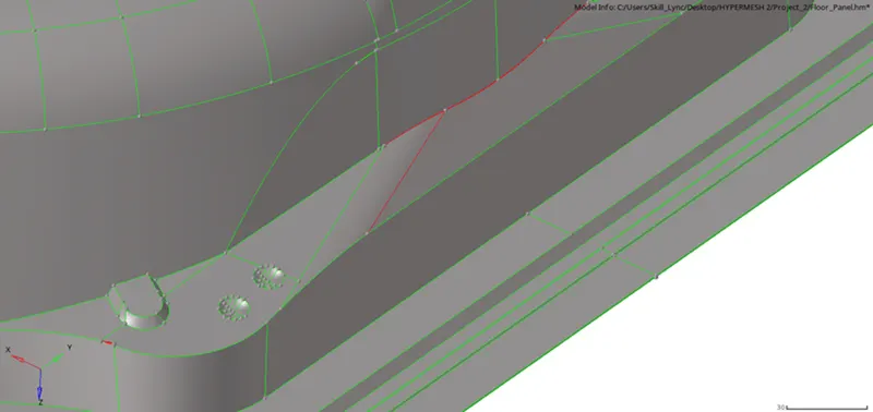
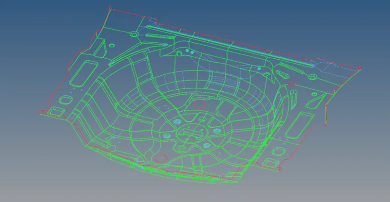
The trim lines in the curved surface in not fully connected to the surfaces and this makes some errors while meshing. To avoid this type of errors split surf-node/split surf-line potion is used. The first option is used to connect two nodes and the second option is used to connect straight line selected.
Toggle edges:
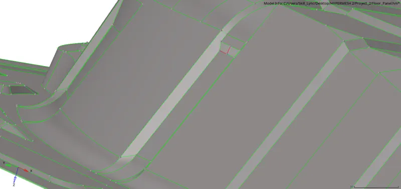
The red line indicates that the line is not shared with the adjacent line and it is called as free edges. To avoid this toggle edge options is used. After togglling the lines the red line is changed to green shared line.
Filler surf:
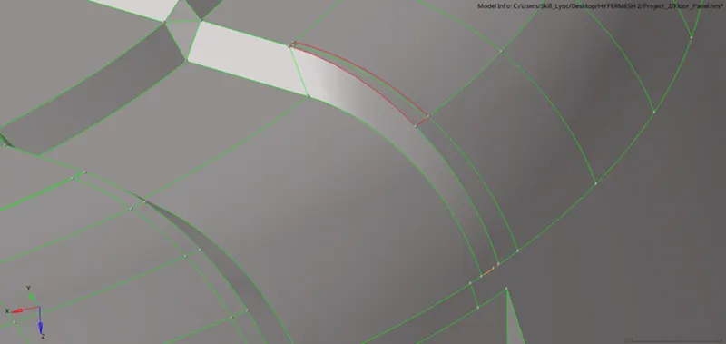
By using the filler surf option the surface is filled. There is also another option used to create surfaces in the missing surface
Geometry--->surfaces, option is used.
Add/remove points:
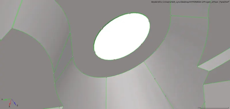
In the fee edge there should be no extra points present it will affect the mesh quality. To remove this unwanted points in the lines, the add/remove points is used.
Project point:
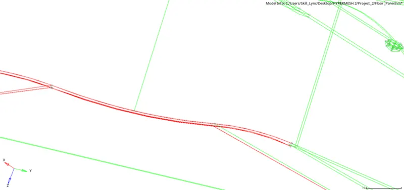
This option is used for pasting two nodes present in two different lines. In this picture, the lines are not connected to the other lines and the hot points are scattered in all the lines in the free edge. So the project point is used to add a parellel point to the adjacent line and join them with the replace point option otr simply toggle the line at the end of the point.
Removing the holes :
The minimum element lenght we got is 2mm and the holes less than 5mm are closed. For that the surface edit option is used.
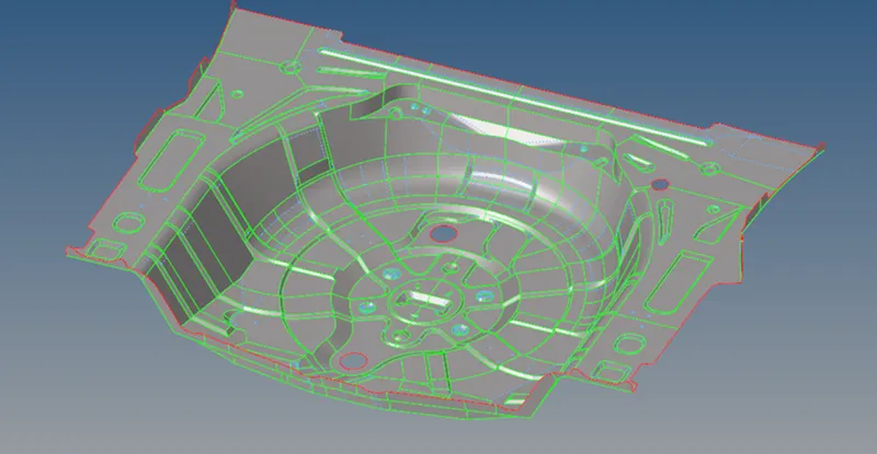
- Mid surface generation:
This will be done once after the geometry cleanup & extraction of mid surface is an important step in CAE which has to be followed.
Mid is the neutral pahse which is been generated from the CAD which is imported or given to us.
The conversion of 3D cad to 2D cad is happening in mid surface generation.
The mid surface is generated to reduce the complexity as by simplifying the cad model we get more accurate simulation results in shorter time.
After the topology cleanup is done the mid surfacing process is started. There are two different methods used for mid surfacing, they are manual midsurfacing, auto midsurfacing. In this challenge I took Auto midsurfacing because the model is a closed volume and having uniform thickness.
The command used to Automidsurfacing is done through Geometry--->midsurfacing.
There are four options used for extracting the middle surface, they are Offset+planes+sweep, offset+planes, offset, skin offset. Each option deals with the specific application for the midsurfacing.
The offset and the skin offset option is used repeatedly for better accuracy in the model.
Offset: Create pieces of the middle surface by offsetting the model's side surfaces towards the middle.
Skin offset: This option is used for uniform thickness components and fastest way of midsurfacing.
Other tools used:
There are other tools used for the small works in the model, they are distance, temp nodes, nodes, line edit options.
Once mid surface is extracted feed in the properties of materials & assign thickness for particular model.
- Shell or solid meshing:
Shell meshing is achieved after skin extraction but we do not mid surface all components based on requirements we should also be doing volumetric mesh.
For casting & molding products we generally go with solid meshing.
For meshing the target element length is 5mm, minimum length is 2mm, maximum length is 8mm. The quality criteria file is inputted to the model. The command used for the automesh is 2D--->automesh. The shortcut used for the automeshing is F12.

The meshing is not done for the whole component in a single shot. Rather than the surfaces are splitted with the lines and seperated into small surfaces. Then the small surfaces are meshed one by one. This makes the mesh flow even in all places.

The density of the mesh is very important. when it is subjected for some external force or shock wave if the mesh is so denser the time step may affected. So the mesh density should be so finer in way to avoid some errors. The density option in automesh option used for adjusting the density of the mesh.

This option is used to modify the style of the mesh and also modify the mesh in the complex areas.
TOOLS USED TO EDIT THE MESH:
To make the mesh better some tools are used they are smoothing, rebuild mesh, quality index, element cleanup, replace, project, edit element, translate, quick edit, mask are used.
Smoothing:
The process of aligning the set of elements in a proper flow. the command used for smoothing is 2D--->smoothing. The shortcut key for smoothing is Shift+F12.
Rebuild mesh:
This option is associated with the quality criteria file and this option automatically modifies the mesh with respect to the surface. This option is only used in the complex regions that the normal automesh is not working properly. The command used for rebuild mesh is
2D--->rebuild mesh.

Quality index:
This tab is used for editing a elements quality parametres like min length, max length, trai elements etc.

Replace panel: Use the Replace panel to relocate one node to the position of another or manually equivalence two nodes. The shortcut used for the replace option is F3.
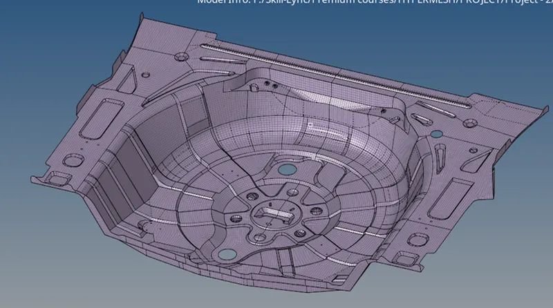
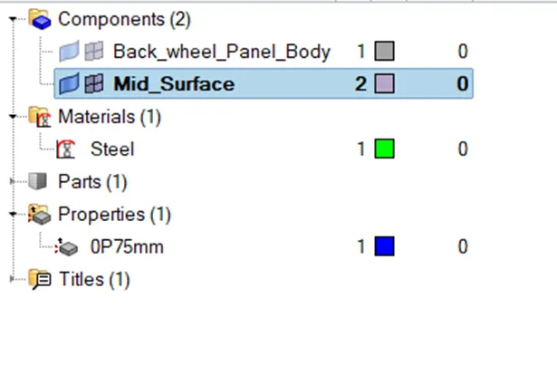
Assign Property, MAT & Thickness -
Since it is a sheet metal part there will be a uniform thickness.
- Element quality check:
Every product which is been produced will go through the set of quality check. If quality check fails other steps like B/C & applying loads will not be feasible, So element quality check will be performed.
The given quality criteria values been enterd in quality crieteria settings under prefernces. These colours are customizable and can be seen while meshing if the elements are beign failed. These failed elements should be corrected and the elements should matches the quality criteria.
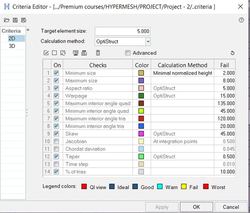
Figure 9. Quality checks.
- Mesh Improvement:
In this phase, the quality of FEM will be improved.
After quality check any improvements that is been addressed that will be done in mesh improvement stage.
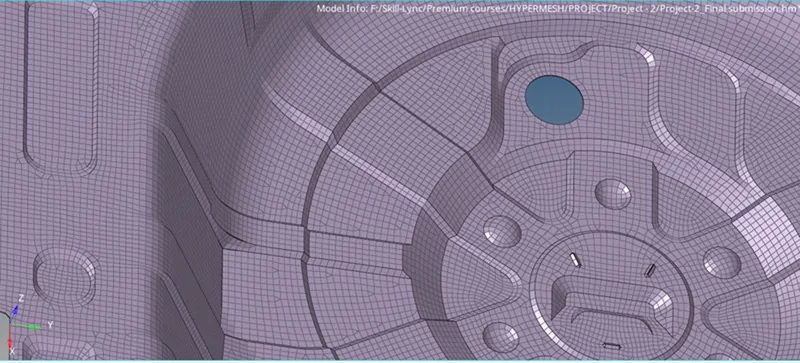
Figure 10. Mesh improvement
- Apply load & BC: Loads & boundry conditions will be applied on this phase.
- Export input file:
Have to choose which software will read the file. As different solvers follow seperate algorithms & process.
Decks: NASTRAN - NVH, PAM CRASH - Safety, LS DYNA - safety, ABAQUS - durability.
2D detailed element representation - It should be activated after finishing challenge. Since it is a shell elements, After activating 2D detailed element representation the meshed shell elements will convert to solid, by considering the thickness assigned on Property card. This is a final stage in this challenge which has to done before submiting.
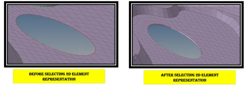
Details of elements
CHECKS:
The checks for,
Comparison
Normal
Free edges
Duplicate elements has been done successfully.
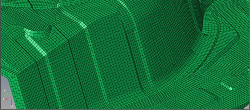
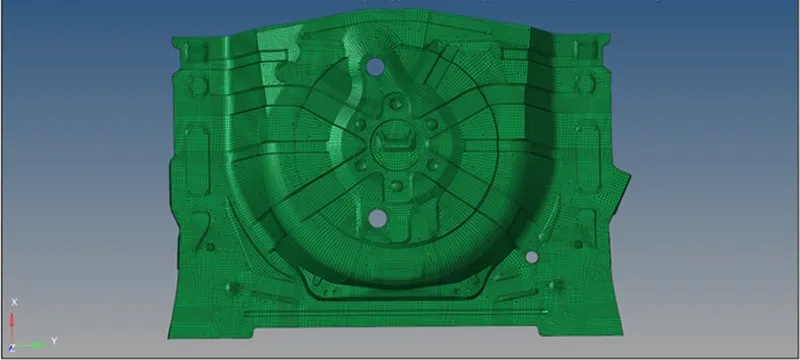
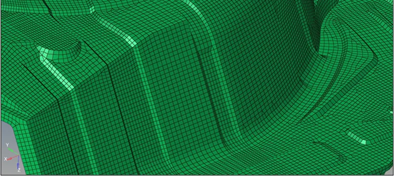
mesh result.
LEARNING OUTCOMES :
At the end of this challenge, I can able to
Easily perform FE Model building for any complex automotive components with a good mesh flow.
Develops better understanding of tools and methods of operation in Hypermesh.