Week 12:Project 2-Meshing of Rear Wheel Holder challenge
Problem Statement:
For the given component, perform mid-surfacing and mesh with the given element Quality criteria. After meshing the component, assign the thickness.
Theory:
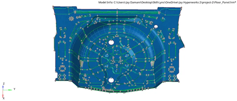
The part is an automobile's spare wheel cover. It houses the spare wheel usually in the trunk of a car. The thickness of the part is close to 0.9 mm.
Procedure -
Procedure:
Following are the steps involved to achieve the objective -
1) Import CAD Geometry - The part file should be of a format supported by Hyperworks (STP., IGES., STEP., etc.).
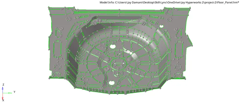
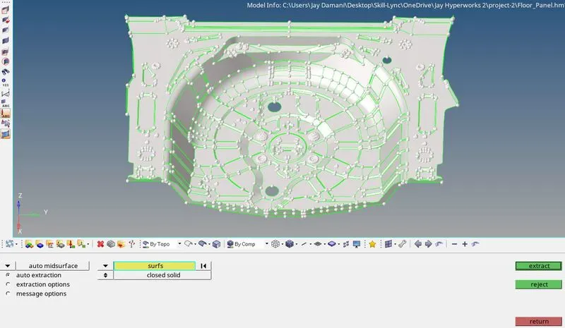
2) Mid-surfacing - Since the geometry is clean we can move onto mid-surfacing. Once a closed volume is achieved, the 2D shell can be created by using the 'mid-surface function under the 'Geo' tab. Under the extraction options, we'll choose the 'offset+planes' option. Once selected, the only input required is the selection of all surfaces and then press create to start the automatic process of mid-surfacing. Check for abnormalities such as cracks and missing surfaces once the process is complete. Fix them using tools used for geometry cleanup.
3) Meshing -
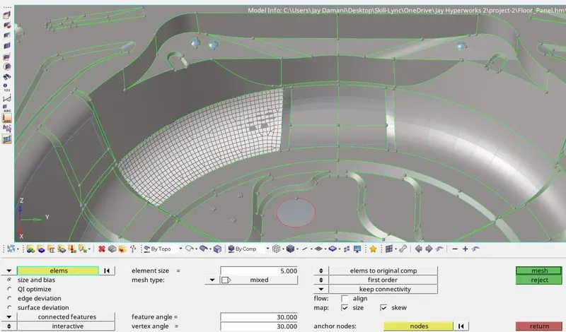
a) Now that we are all set for meshing, we firstly select an area to start from. A good practice would be to move from the middle of the part towards the outer edges. This leaves some flexibility for rearrangements while in the other case, the area becomes constrained by the surrounding mesh. Element type and size are set to 'mixed' and '5' respectively.
b) Larger areas should be sub-divided by creating split lines. This helps better regulate mesh quality. Small changes to the mesh's flow and arrangement can be made by altering the number of nodes on each edge. If this does not suffice, the function 'rebuild mesh' under the '2D' tab can help improve the mesh. Firstly the mesh criteria have to be set to the given mesh quality parameters after which the elements are selected which require betterment. Running this should output a mesh that fulfills all quality criteria and maintains good mesh flow.
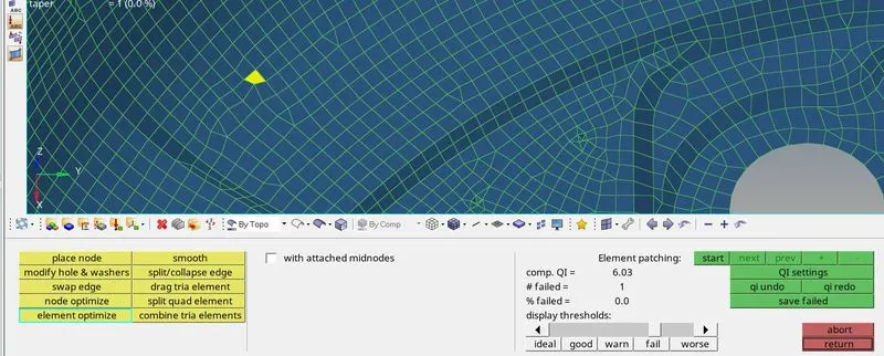
c) Further changes can be made to the mesh using the 'quality index' function under the '2D' tab. This checks all elements in the model for quality errors and provides to cleanup any such errors. Cleanup tools such as 'smooth' and 'element optimize' automatically make minor adjustments to the mesh to improve flow and adjust elements to clear quality criteria. Others such as 'place node', 'drag tria elements', 'combine tria elements', etc. allow for manual changes to the mesh.
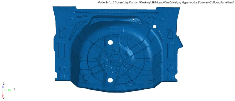
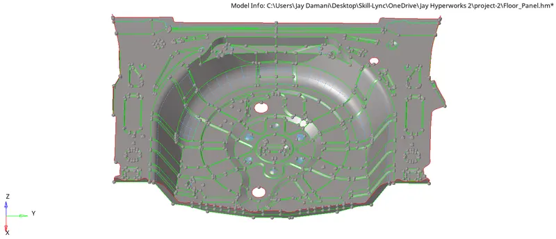
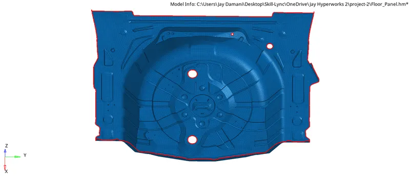
4) Check for free edges - To check for element connectivity, the 'edges' function under the 'tools' tab can be used. The only input required is the component selection and the output is shown as red free edges. An unnecessary free edge in the middle of a component can be thus noticed and corrected easily.
6) Creating material cards, assigning properties, and thickness - A material card is created to define the material properties of each part such as the young's modulus, Poisson's ratio, etc. The default values in a material card are that of steel and we'll be using the same. These material cards are then selected while defining the property cards for each part. The property cards allow us to define the type of elements in the parts wiz. 2D shells in our case hence we'll be using the property 'PSHELL'. Here we also input the thickness of the part. These property cards are then assigned to each component. All this is accomplished in the model tree segment of the GUI. A thickened version of the 2D shells can be visualized using the '2D detailed element representation' option under the visualization tab.
Final CAD Images