Week 12:Project-1-Meshing of Door Inner Panel Challenge
OBJECTIVE:
Follow the Quality Criteria and mesh the following component and assign thickness:
Target Element Length = 4 Units
| S.N | Quality Criteria | Value |
| 1 | Aspect Ratio | 5 |
| 2 | Skewness | 45 |
| 3 | Warping | 15 |
| 4 | Taper | 0.5 |
| 5 | Min. Length | 2 Units |
| 6 | Max. Length | 6 Units |
| 7 | Min angle Quad | 45 |
| 8 | Max angle Quad | 135 |
| 9 | Min angle Tria | 20 |
| 10 | Max angle Tria | 120 |
| 10 | Tria % | 10 |
Important Points to Remember
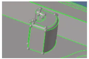
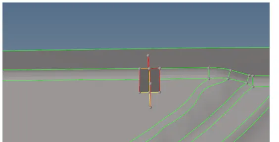
- The area which is having more than 6mm thickness should not model in 2D. You can capture them like in the Below-mentioned picture
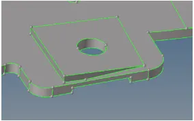
- The below image has some geometrical issue on it so modeling them in the 2D will be difficult.
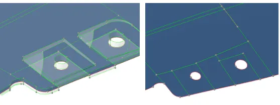
- In those areas, the main objective is to capture the hole so we can take a mid surface by creating a flat surface with a hole like an image below.
- No need to model the below-mentioned area. The mentioned area does not have a proper attachment to the model.
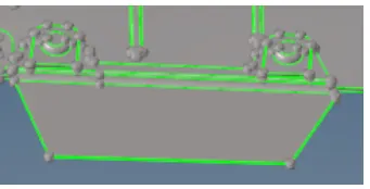
- For variable thickness areas, Assign the thickness taking an average value of the cross-section
SOFTWARE REQUIRED: Altair-Hypermesh.
ABOUT SOFTWARE: It is a preprocessor tool which is used for modelling of any component in CAE domain.
ABSTRACT: It is a plastic door inner panel which is attached to the every door of a car which is used for extra elegant look for car and to make a door smooth.
INTRODUCTION:
II. Exsisting Inner Door Panel Design
Inner door panel is a component which is usefor strengthening the door assembly and it is one of themost important components on witch all accessories are mount like hinges, glass guide channel. Front door sill,window winding regulator, hard pad, molded trim, latch etc. Front door inner panel is use for sealing purpose when the primary sill is mounted on this. The weight of Door inner panel is near about 7to8kg depends upon its material and its thickness. The possible method is the integration method. In the integration method, the part is
stamped out of a single blank. This reduces the number of tools needed; the assembly cost, and eliminates any fit ability problem. However, the design engineer is forced to work with same grade, thickness, and corrosion resistance throughout the entire part. Since the most demanding of all these conditions must be satisfied for the entire blank, this would increase the cost and weight of the part.
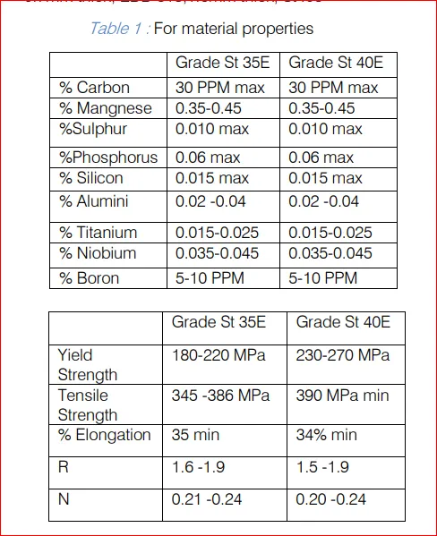
III. Design Of New Door Inner Panel ForReducing Cost And Weight Of Front Door:
In this paper we are going to reduce weight of a front door assembly by using tailor welded blank concept for front door inner panel and using less
thickness high strength material and reducing cost by replacing molded trim with hard pad in front door assembly and saving 1400 Rs/set.
a) Methods of preparing inner door panel
1. In current automotive stamping technology, there are two basic paths that can be followed to arrive at
the final inner door panel. The first method is part disintegration or part separation. In this technique, each different section of the blank is stamped separately and then spot welded together in the shape of the final part. This method has numerous advantages such as the ability to select the specific properties, i.e. the strength, thickness, corrosion resistance, etc. of each area of the blank. This method also gives a higher yield ratio of material used.
2. The other possible method is the integration method. In the integration method, the part is stamped out of a single blank. This reduces the number of tools needed; the assembly cost, and eliminates any fit ability problem. However, the design engineer is forced to work with same grade, thickness, and corrosion resistance throughout the entire part. Since the most demanding of all these conditions must be satisfied for the entire blank, this would increase the cost and weight of the part significantly.
3. A solution to the problems listed above is the utilization of tailor-welded blanks. A tailor-welded blank is a blank that is comprised of two separate pieces of sheet metal that has been welded together previous to stamping. Tailor welded blanks allow the welding of the different grades, different thickness or different corrosion coatings together in order give the properties needed in different areas, without increasing the number of tools needed to form the part and eliminating the fit ability concerns. They also allow a high degree of flexibility in designing parts and large blanks can be formed from much smaller sheets .The use of tailor-welded blanks would reduce the weight of the car. Having the ability to selectively place different thickness of material would result in weight reductions. An example of this used in production is the door inner panel. The only strength requirement on a doorinner is in the region where the hinges attach to the panel.
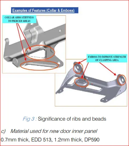
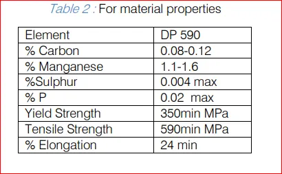
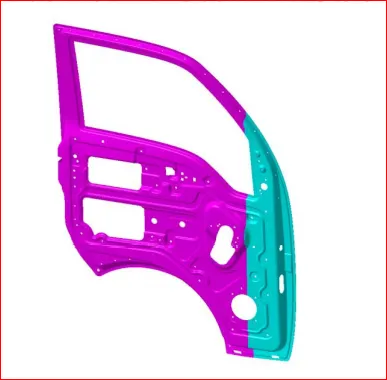
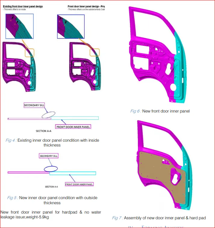
d) Design of new door inner panel for solving water leakage issue Tailor Welded Blanks are made from individual steel sheets of different thickness, strength and coating which are joined together by laser welding. When we design inner door panel with tailor welded blank in witch some portion of a panel having different thickness and other is different. In our case some portion of door inner panel is 0.7mm thick shown below with pink color and another is 1.2mm thick shown below with sky color. There is a 0.5mm gap between these two thicknesses and this is the reason that water is leakage between door inner panel and secondary sill in shower test. Below figures gives the idea of existing and new coditions.
IV. Forming Analysis:
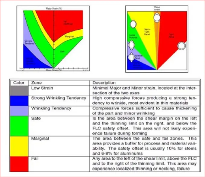
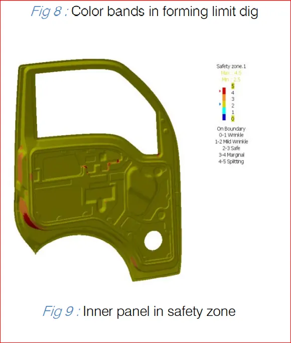
The technique of sheet metal forming analysis requires non-contact optical 3D deformation measuring system. The system analyzes, calculates and documents deformations of sheet metal parts, for example. It provides the 3D coordinates of the component's surface as well as the distribution of major and minor strain on the surface and the material thickness reduction. In the Forming Limit Diagram, the measured deformations are compared to the material characteristics. The system supports optimization processes in sheet metal forming by means of; Fast
detection of critical deformation areas, Solving complex forming problems. The optical forming analysis with forming analysis system provides for precise and fast measurement of small and large components using a high scanning density. Forming analysis system operates independently of the material. It can analyze components made from flat blanks, tubes or other components manufactured by an internal high pressure forming process (Hydro forming). The Forming limit curve is used in sheet metal forming for predicting forming behavior of sheet metal. The diagram attempts to provide a graphical description of material failure tests, In order to determine whether a given region has failed, a mechanical test is performed. The mechanical test is performed by placing a circular mark on the work piece prior to deformation, and then measuring the post-deformation ellipse that is generated from the action on this circle.
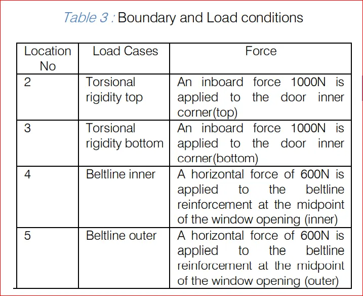
V. Cae AnalysisTo evaluate the stiffness and sag performance of the front door for both existing and hard pad. Different stiffness’s considered for front door assemblies are. The objective of this analysis is to predict the vertical sag behavior of the front door assembly of CUB (Goods Carrier). As per the procedure, there should not be a permanent set exceeding 1 mm and maximum latch point deflection (elastic) should not be more than 10 mm. At the latch point under two conditions.
a) Results
Stiffness Analysis :
1) Predicted vertical stiffness of door with hard pad interiors is lower than existing front door design
2) Predicted beltline inner stiffness of door with hard pad interiors is lower than existing front door design
3) Predicted beltline outer stiffness of door with hard pad interiors (CAE Proposed design) is equivalent to existing front door design
Door Sag Analysis :
Predicted maximum elastic deflection and permanent set in door under worst door sag load case
are as follows.
1) Existing design: Maximum elastic deflection is
7.75mm and permanent set is 0.23
2) Hard pad design: Maximum elastic deflection is
9.27mm and permanent set is 0.34
VI. Conclusion
In this paper we design new front door assembly components with tailor welded blank technology for reducing weight and cost of door assembly. Tailor-welded blanks allow combining
different strengths of steel in one part without adding complications at the joints. Weight of a door assembly is reducing by 0.4 kg, by reducing weight of a door inner panel by using less thickness high strength material, reduce cost by replacing molded trim with hard pad. We are successfully solved water leakage problem by modeling front door inner panel correctly.
PROCEDURE:
1) IMPORT A CAD MODEL
2) GEOMETRY CLEANUP
3) MID SURFACE EXTRACTION
4)SHELL/SOLID MESHING
5) ELEMENTARY QUALITY CHECK
6) MESHING IMPROVEMENT
7) APPLY LOAD AND BOUNDARY CONDITONS.
8) EXPORT IMPORTED CAD MODEL.
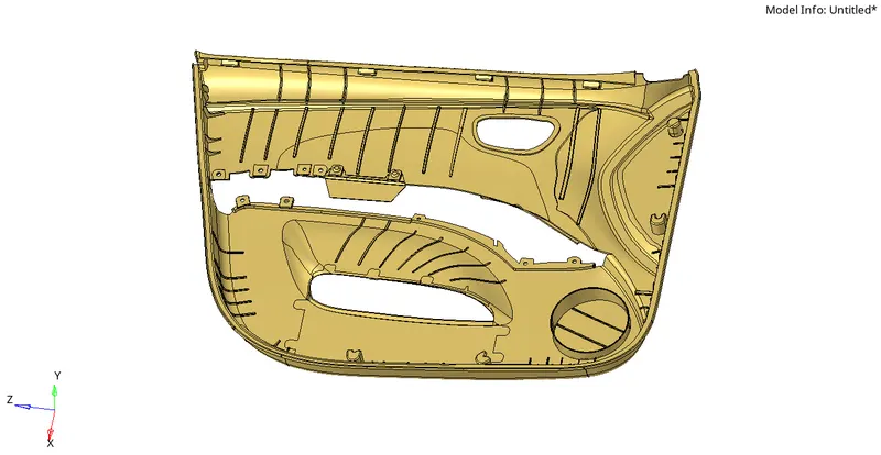
1) IMPORT A CAD MODEL: This is the first step in any preprocessor tool we have to import a cad model.
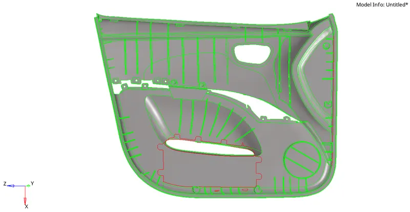
2)GEOMETRY CLEAN UP: If any unnecessary triple cons ,double cons, single cons , sharp corners, free edges etc. as a cae engineer we need to cleanup the geometry by manually using quick edit, edge edit, lines, and surfaces commands.
3) MID SURFACE GENERATION: This is the first step to take after completing the geometry cleanup.it is maily depending on component, we need to identify weather we are working with the sheet metal component ,plastic trim , etc.
- If the thickness is greater than 5mm we will choose solid meshing.
- If the thickness is less than 5mm we will go for shell meshing.
- if the thickness might be uneven then also we will choose solid meshing.
here i am taking a mod surface by using mid surace command, in that command it has some types of methods
- skin offset
- offset
- sweep+planes
- offset+plane+sweeps.
by manually checking with different components with different algorithms then only will get which method is best for which component.
generally skin offset gives the better results while taking a mid suarface, sometimes offset command.
below figures represents the mid suface extraction from parent geometry.
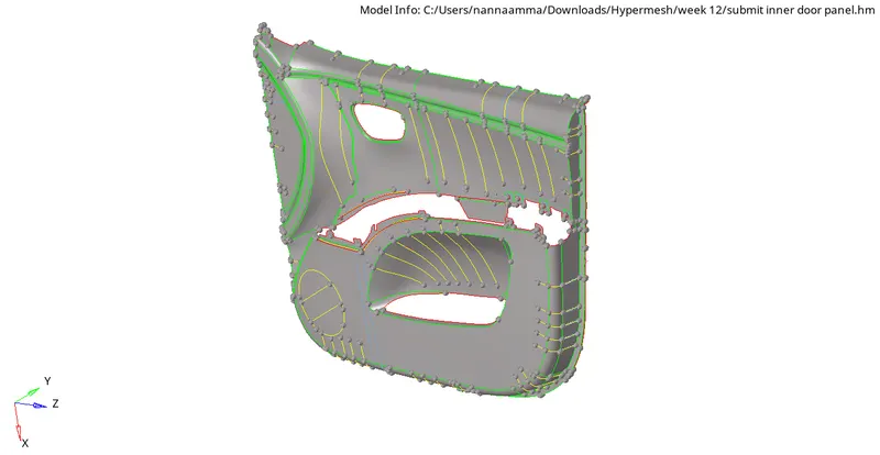
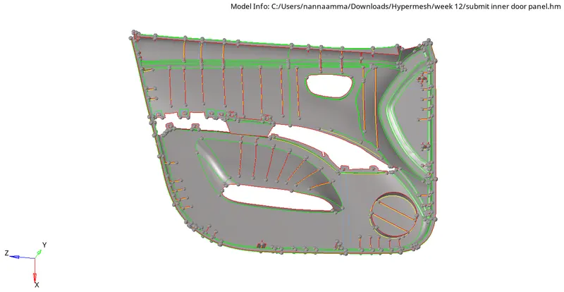
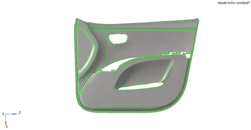
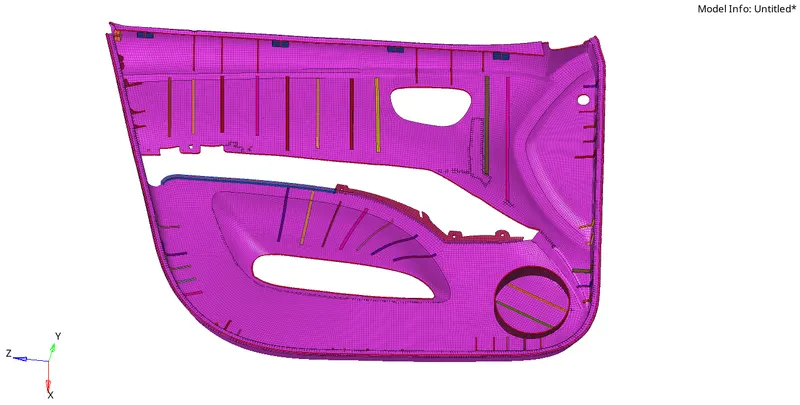
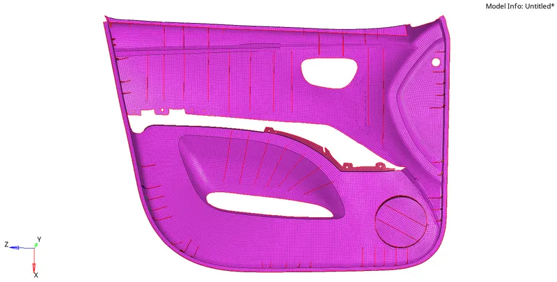
4) SHELL/SOLID MESHING: This component is sheet metal so the thickness is also same throughout the component. so i prefered shell meshing.
below figures represents the shell meshing parts.
5) ELEMENTARY QUALITY CHECK: The main use of this quality criterians it tells about how our mesh flow is.
- A good mesh flow improves result accuarcy with lesser computational time.
- A bad mesh flow provides longer simulation run time with less accuaracy.
WARP ANGLE:The angle between two local normals is called warpangle.
It is possible only if four elements available, let us take a quad element so it has four nodes then we made a cut diagonally we got two tria in the quad . so each tria element have one local normal.
SKEWNESS: an ideal tria element has an equilateral triangle and an ideal quad has a square. it is used to find the deviation from any side.
it is recommended to maintain a skewness less than 45 .
ASPECT RATIO: it is used to calculate the length of all elements .(or) it is the ratio of maximum edge length to the minimum edge length.
because of this we will get a perfect elements in quad shape.
it is recommended to maintain the aspect ratio is less than 5mm.
JACOBIAN: It is the short from for the determinant of the jacobian matrix, it does co ordination transformation.
it is used mainly we will convert critical co ordinate system to simpler co ordinate system.
it is recommended to maintain less than 1mm and greate than .6mm.
the deteminant of jacobian helps in identifying the distortion.
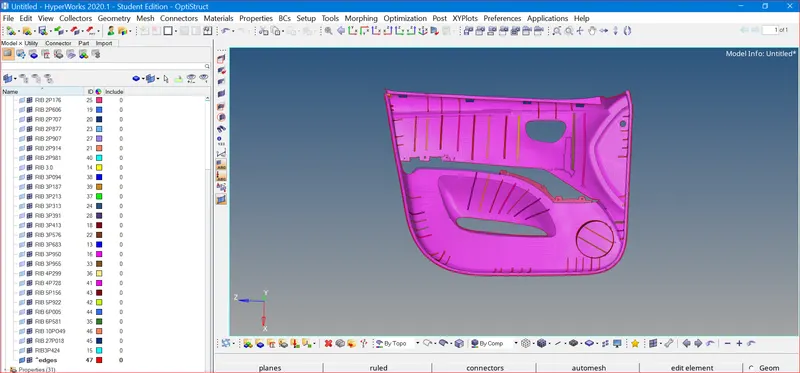
ASSIGNING THE THICKNESS: we have to assign the thickness as per the requirement and depending on the dimensions of a component.
here for all components have thcikness so i have assigned the thickness depending upon the component.
below figure represnts the thickness assigning.
RESULT: I have
- Imported a cad model
- cleaning up the geometry
- taken a mid surface
- done meshing
- assigned the quality criteria
- assigned the thickness.
- tria percentage of - 1.3%.

Learning outcomes: I learned how to
- import a cad model
- clean up the geometry
- take a mid surface
- assign the quality criteria
- make meshing
- use drag tria and element optimization options.
- made a reflect
- give a distance
- make a translate.
- take a mid surfce manuallly.
- remove the free edges using shift +f3 command.
- how to add new command in hypermesh.