Week 12:Project-1-Meshing of Door Inner Panel Challenge
AIM:
To mesh the given model with the given quality criteria and to assign thickness.
PROCEDURE:
STEP 1:
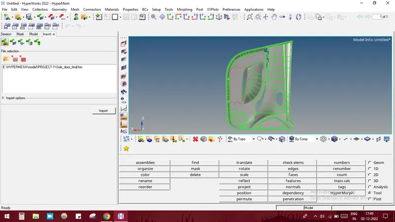
Import the given model into hypermesh by selecting IMPORT SOLVER DECK-IMPORT GEOMETRY-SELECT THE FILE-IMPORT.
STEP 2:
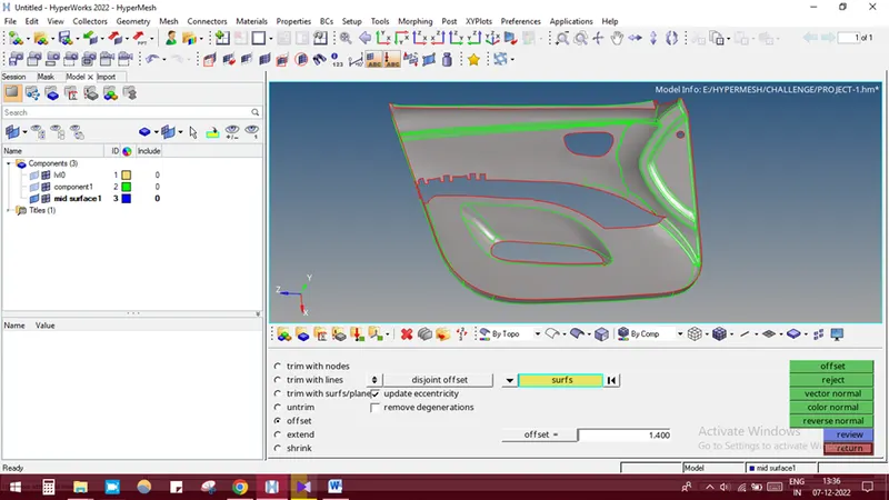
Create a new collector component and name it as mid surface.
Measure the thickness of the component by projecting the points on two different surfaces and use f4 to measure the distance.
Offset the surface by selecting GEOMETRY-SURFACE EDIT-OFFSET-SELECT THE SURFACE-BY FACE-DUPLICATE-GIVE OFFSET VALUE-OFFSET.
STEP 3:
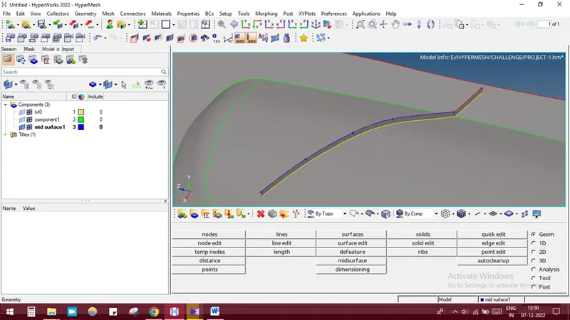
Create the ribs by selecting GEOMETRY-LINES-MID-LINE-SELECT THE LINES-CREATE.
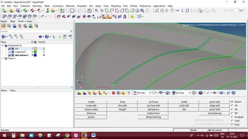
Project the lines into the surface by selecting GEOMETRY-SURFACE EDIT-TRIM WITH LINES-SELECT THE SURFACE-SELECT THE LINES-TRIM.
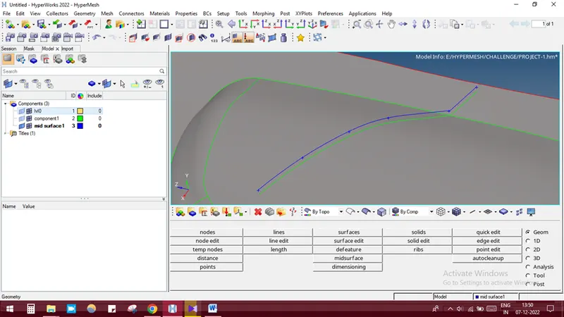
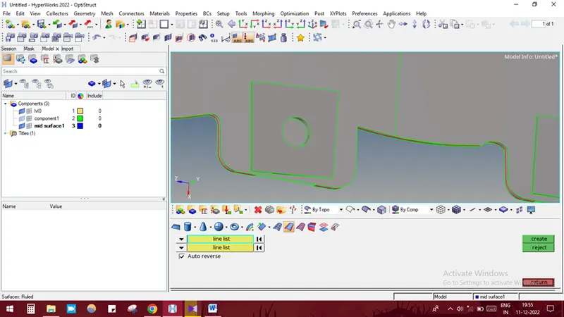
Create the surface by selecting GEOMETRY-SURFACE-RULED-SELECT THE LINES-CREATE.
Creating holes at the mid surface region
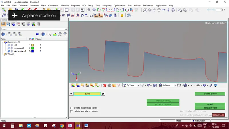
But the actual mid surface looks like this
So we are creating surface at this region
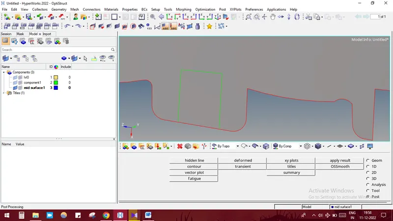
By using the surface edit option, the circle could be created at the mid surface by selecting GEOMETRY-SURFACE EDIT-TRIM WITH LINES-SELECT THE SURFACE EDGES-SEECT THE SURFACE-SELECT NORMAL TO SURFACE OPTION-TRIM.
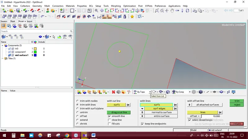
Then the surface could be selected and deleted by using the delete option.
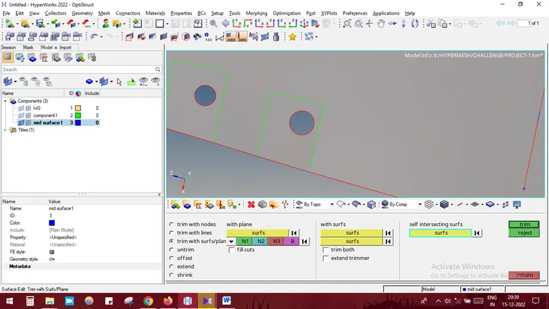
Dog house capturing procedure is explained as follows
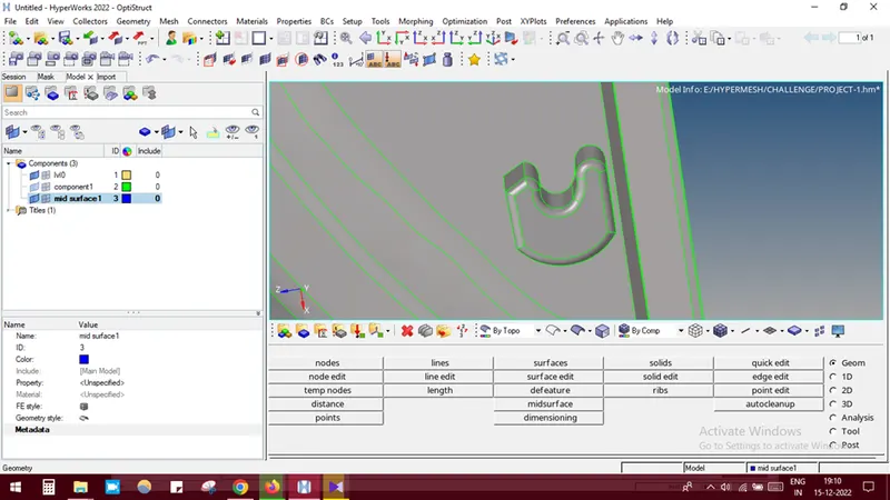
Initially create a cross line by using GEOMETY-LINES-LINEAR NODES-SELECT THE NODE-CREATE. Use surface trim option to create lines on the base surface
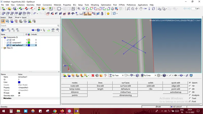
Use SURFACE-LINE LIST Option to create the surface.
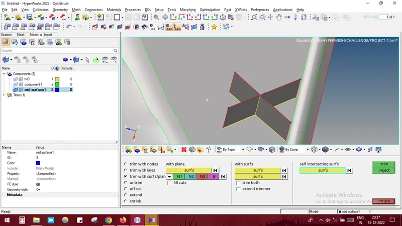
In some areas the components has a different thickness so the new collector component has to be created and in that the mid surface of the particular component has to be assigned manually using the OFFSET option. The image below shows about this.
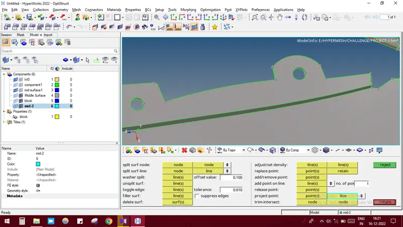
After offset it looks like this
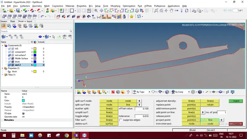
Then these two surfaces are to be joined. For that initially the end points of the small surfaces are projected to the opposite surface using the QUICK EDIT-PROJECT POINTS option.
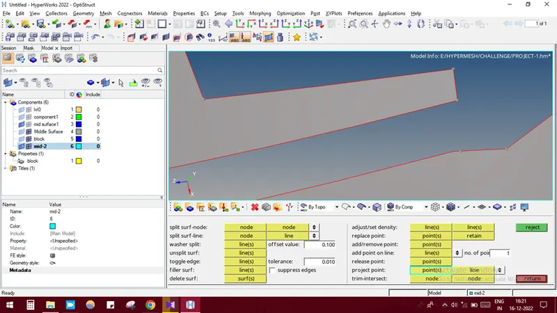
In GEOMETRY-SURFACE-DRAG ALONG VECTOR-SELECT THE LINE-GIVE N1 AND N2-GIVE DISTANCE-DRAG+ which is used to join the two surface.
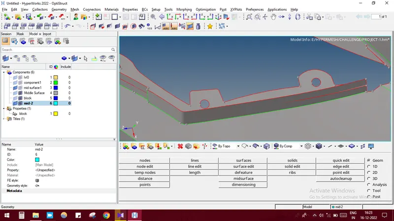
Since both the parent surface are intersecting so the mid surfaces are also to be intersected so in GEOMETRY-SURFACE EDIT-EXTEND –LINES TO EXTEND OVER-SELECT THE MIDDLE INTERSECTING SURFACE LINE-SURFACE TO TARGET-SELECT THE SURFACE WHICH GETS INTERSECTED-MIDDLE CLICK.
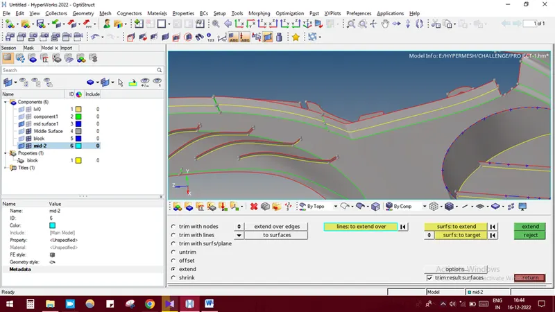
In some regions, after offset there might be some gaps present it could be easily eliminated by using extend option from SURFACE EDIT-EXTEND-MAX EXTENSION-CROSS EXTENSION-SELECT THE SURFACE TO BE EXTENDED-EXTEND.
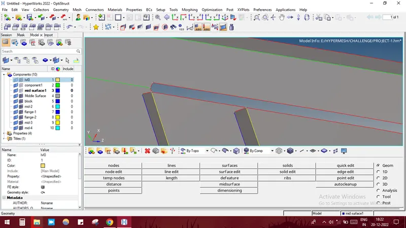
After using the option, the surface looks like this
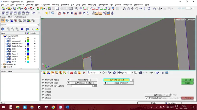
After creating the mid surface it actually looks in this manner with all ribs and mountings
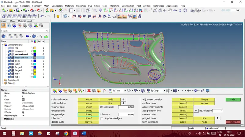
In some areas, there may be a few surface imperfections due to openings. These could be cleared using the edge edit option. GEOMETRY-EDGE EDIT-REPLACE-SELECT THE LINE WHICH NEEDS TO BE MOVED-SELECT THE RETAINED LINE WHICH IS TO BE FIXED-GIVE CLEANUP TOLERANCE VALUE OF 5-REPLACE.
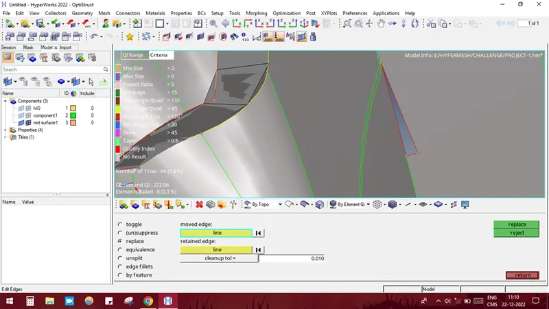
After using edge edit option,
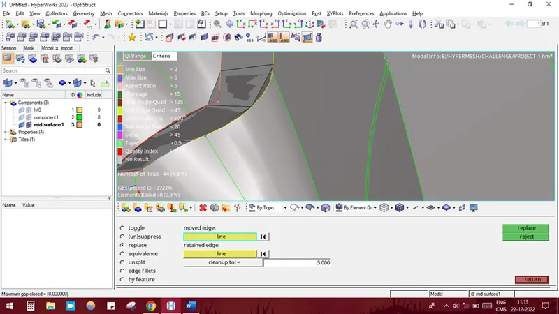
STEP 4:
Meshing the mid surface, initially, the regions which are critical is selected and meshed. The regions present in ribs and its rib side surface are to be meshed.
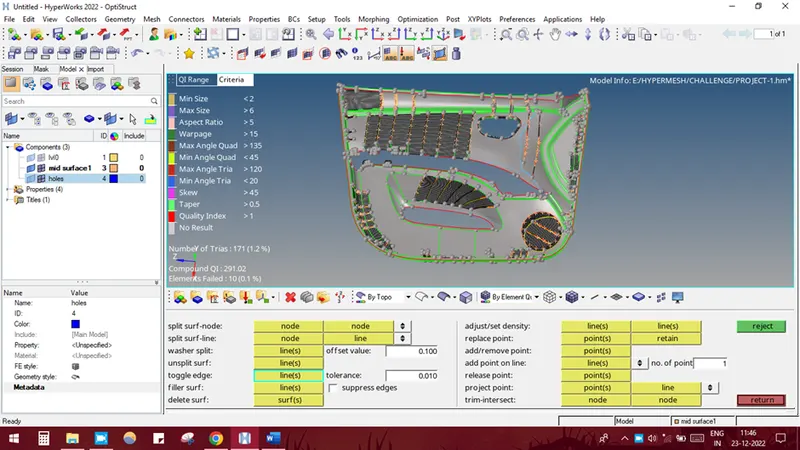
In case of warpage failure
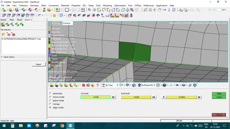
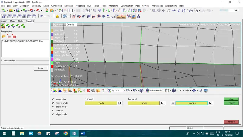
It can be resolved by align option. Press F7-align-select the first node-select the last node-select the in between node which is to be aligned-middle click. By doing so the node will get align and element failure can be rectified.
STEP 5: Checking of mesh connectivity
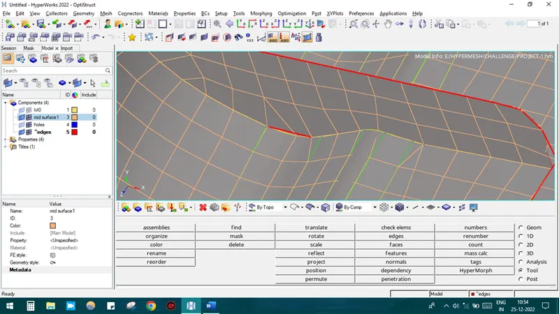
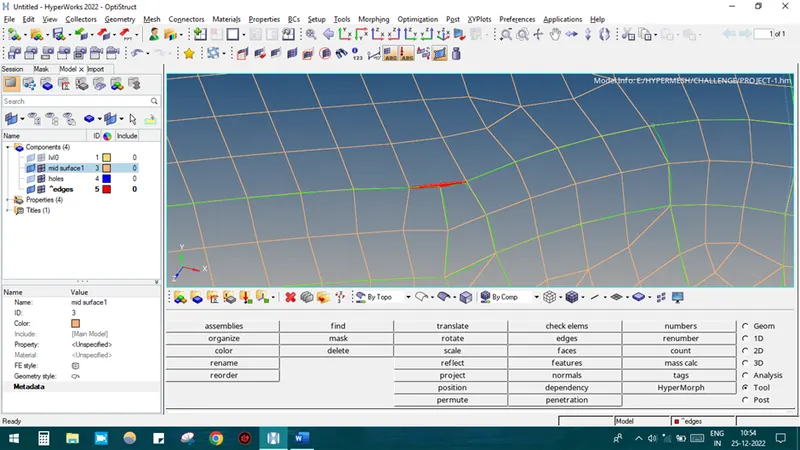
After completing meshing we have to check for mesh connectivity using EDGE option by selecting TOOL-EDGED-ELEMENTS-DISPLAYED-FIND EDGES. Switch on the wireframe elements skin only option.
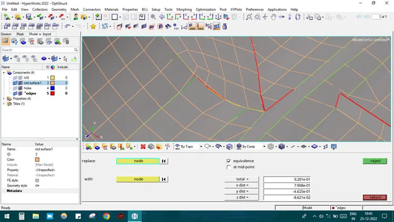
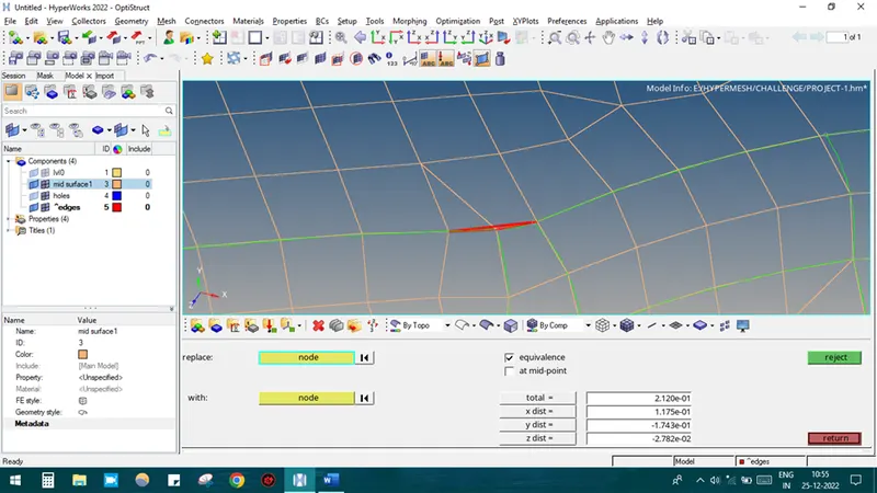
The red lines are indicating free edge as there was no mesh connectivity. So we have to do mesh connection in manual method.
It could be done by splitting the elements using F6 option and connecting the node with the neighboring element node by F3 replace node option.
STEP 6: Assigning thickness
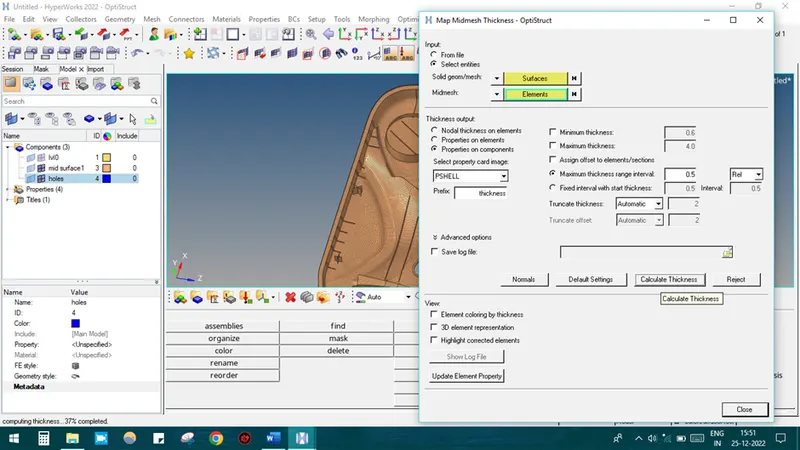
In the top panel, MESH-ASSIGN-MID MIESH THICKNESS-SOLID GEOM/MESH-SELECT THE PARENT GEOMETRY SURFACE-ELEMENTS-SELECT THE ELEMENTS IN THE MID SURFACE GEOMETRY
GIVE MAXIMUM THICKNESS RANGE AS 0.5
SWITCH ON PROPERTIES ON COMPONENT option
Click CALCULATE THICKNESS option.
Then the software does calculate and gives the thickness accordingly.
STEP 7: Assign material and properties
Right-click on the menu bar CREATE-MATERIAL AND PROPERTY.
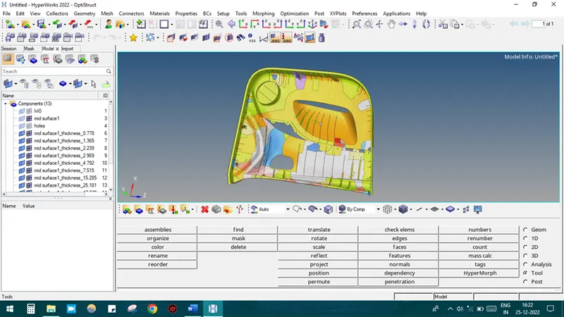
The final image of the model has shown below.
LEARNING OUTCOME:
From this project, I have learned about how to do mid-surface on the door inner panel and meshing the same.
CONCLUSION:
Thus the given inner door panel mid-surface was extracted, meshed with the desired quality criteria and thickness was assigned.
---------------------------------------------------------------------------------------------------------------------------------