Week 12:Project-1-Meshing of Door Inner Panel Challenge
#13 // Week 12: Project-1-Meshing of Door Inner Panel Challenge.
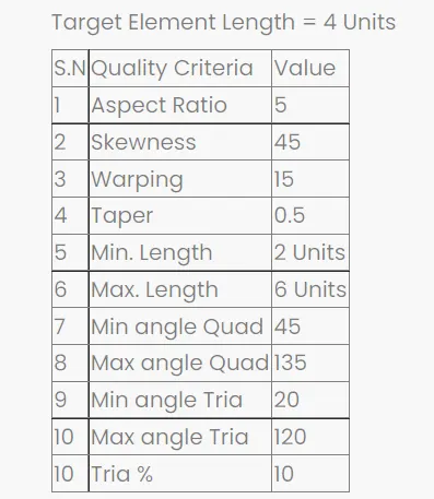
AIM: To extract the mid surface and generate the mesh the given plastic component of door inner panel within given quality criteria and assigning thickness to it.
OBJECTIVE:
- Importing geometry and clean-up.
- Generating Midsurface and geometry clean up on the given component.
- Meshing the geometry within the given quality criteria.
- Model should pass all the given quality parameters.
- Assigning Thickness to component.
INTRODUCTION:
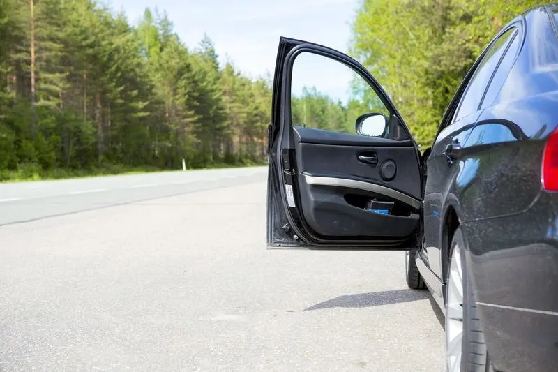
The door panel covers internal parts like the door handle, window switch, the power window motor, wiring, cup holder, audio speakers, storage compartment and other features. Mostly cars have door panels made from plastic most often using injection moulding, as well as incorporating other decorative materials. The door panel typically incorporates other parts that contribute to the appearance, functionality, and ergonomics of the vehicle. In most cases, the door panel is attached to the car's door frame by visible screws and ones hidden behind decorative plugs or under the armrest, as well as spring clips.
PROCEDURE:
- Importing Geometry and clean up:
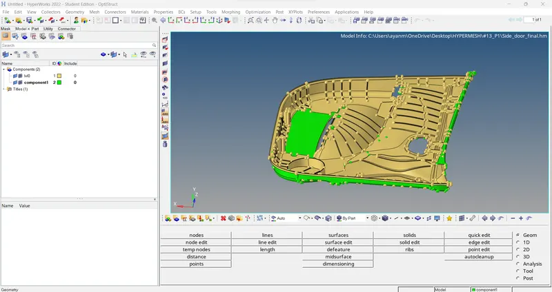
- To import the geometry, go to file > Import > select the file > Import.
- After importing the geometry, the geometry is checked for any missing surfaces or triple cons. If there are no errors present in the geometry then the geometry is ready for the mid-surface extraction.
2.Generating Midsurface and geometry clean up on the given component.
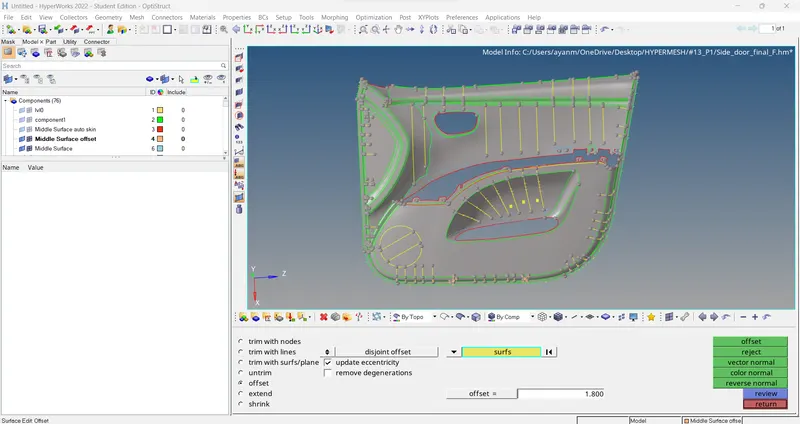
- Mid-surface can be extracted either using automid or manually (using offset option). In this challenge the automid is failing to give the accurate mid-surface so manual mid-surface option is used.
- To manually extract the mid-surface, go to surface edit > offset > enter offset value > select the surfaces > select duplicate > offset.
- After extracting the mid-surface, it is checked for any geometrical errors like needle faces, missing surfaces and triple cons.
- For feature regions we can go with Geom > lines > Midline.
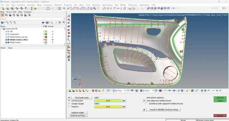
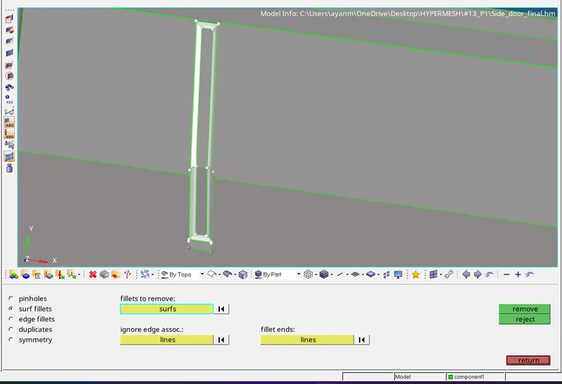
- Or we defeature fillets in feature regions and then go for Geom > Midsurface > final edit tools > select two opposite faces > extract. It gives midsurface for features perfectly.
> MidSurface....
> For Defeature fillets..
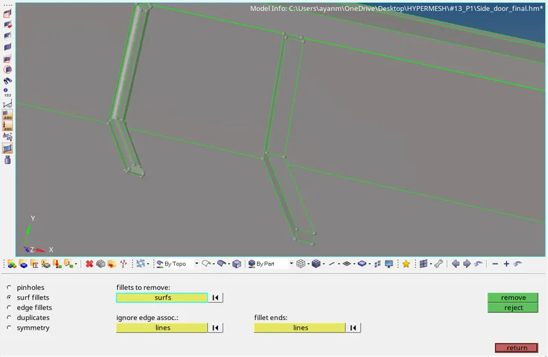
- Go to 2D > auto-mid > Final edit tools option for auto mod generation. This option is usually used for ribs that contain varying thicknesses.
- select the opposite surfaces as shown below and make sure you tick those extraction options as these will connect generated surface to the main mid surface automatically.
> for create midsurface for fillets region use final edit tool in geom > midsurface..
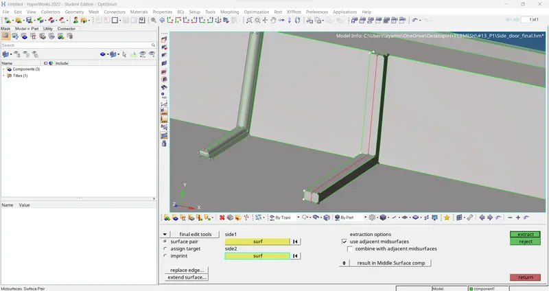
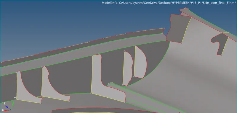
> some features mid-surface by final edit tool.
> or else create mid lines by Geom > lines > Midline, Project it to mid-surface by geom > surface edit > trim with lines & create surface by surfaces > ruled option.
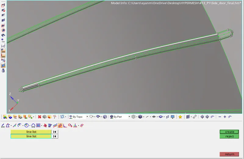
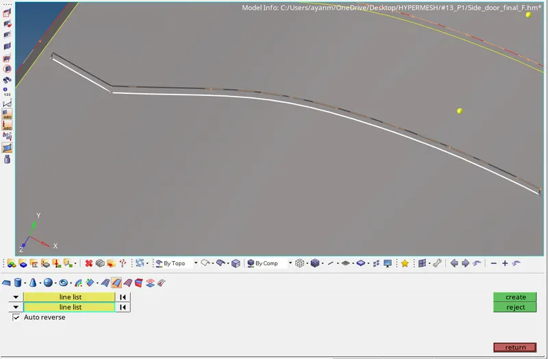
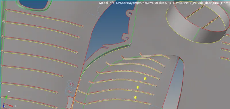
> some features mid-surface by line's Midline option.
// Note:
- for Extend created surface to base mid-surface use Geom > surface edit > extend.

- and also for geometrical clean-up use Geom > quick edit (F11) > Toggle edges / unsplit surf / delete surf / replace point / add or removed point / project point etc.

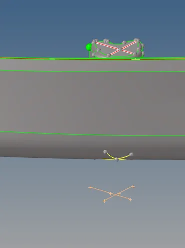
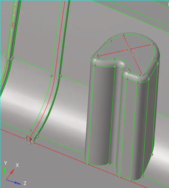
- for dog-house type features, first create node to node lines at the top then duplicate it & translate (shift+F4) to bottom and the ruled with top & bottom lines, after that intersect this cross surfaces.
//
3.Meshing the geometry with in the given quality criteria:
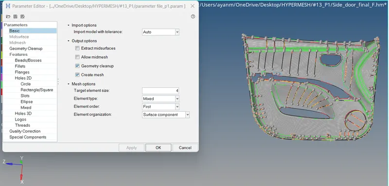
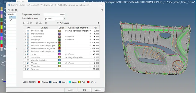
- Before generating mesh, we have to set parameter file settings & Criteria file settings in preferences option.
- To generate mesh, go to 2D > auto mesh > select the surface > mesh. To edit the mesh for proper flow, the elements are selected and meshed again.
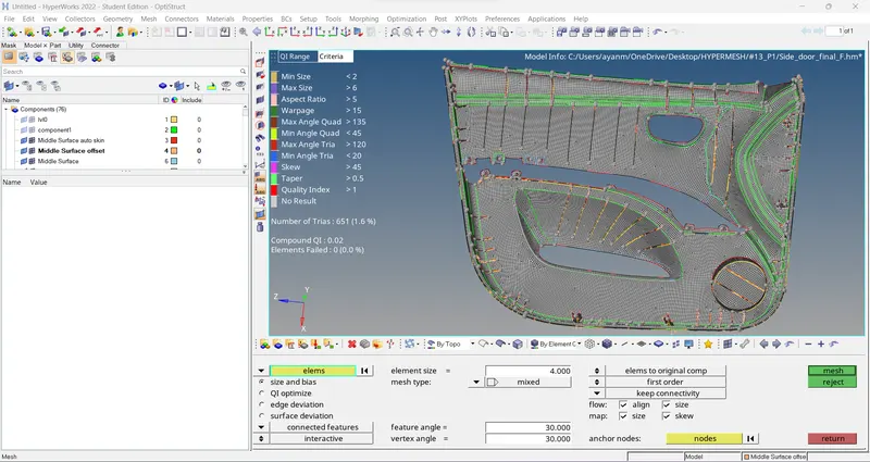
4. Model should pass all the given quality parameters:
- To deal with off elements –
- If any elements are failing for quality, then clean-up tools option which is present in quality index can be used.
- Also we can use 2D > rebuild mesh to get better mesh flow & clear off elements in that particular region.
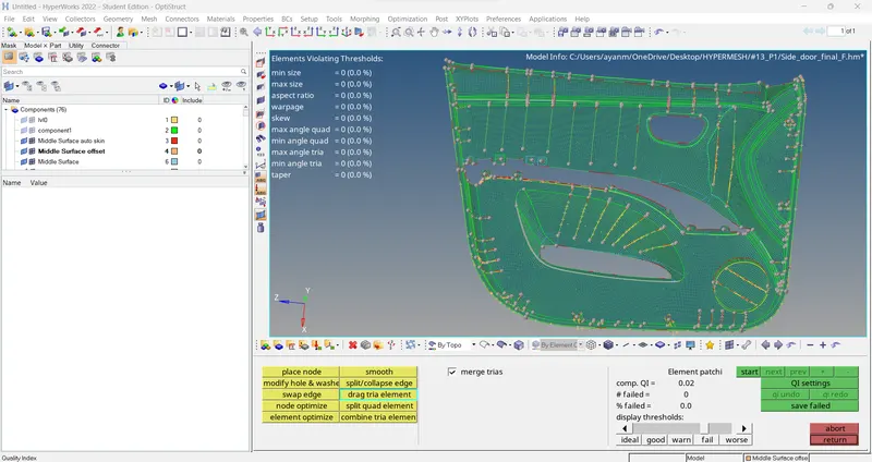
// Note:
> Clean Up tools for clearing off elements and to achieve better mesh flow -
- Use 2D > Quality index tool > Clean up tools (Smooth, drag tria elements, Element optimize, combine tria element, Split quad element, Place node) to eliminate all off elements.
- Smooth: This option helps us to achieve better mesh flow. After clearing off elements, we usually use smooth in that area.
- Drag Tria Element: we can drag any tria element out of the geometry easily. This option helps us to remove trias easily.
- Split Quad Element: Splits one quad into two trias. We use this to reduce rotating quads.
- Combine Tria Elements: Combines two tria elements into one Quad element. Helps in Reducing tria percentage
- Element Optimize: Smooths the quality by adjusting the neighbouring elements. Helps in Clearing elements for quality.
- Place Node: This option allows us to manually change the position of a single node. Helps us to clear off elements.
//
5.Assigning Thickness to component:
- In the model the thickness of the ribs is different, calculating thickness and assigning it to each rib takes time so automatic thickness is used. To use the automatic thickness, go to option panel mesh > assign > midmesh thickness > select surfaces and elements > enter property name > calculate thickness.
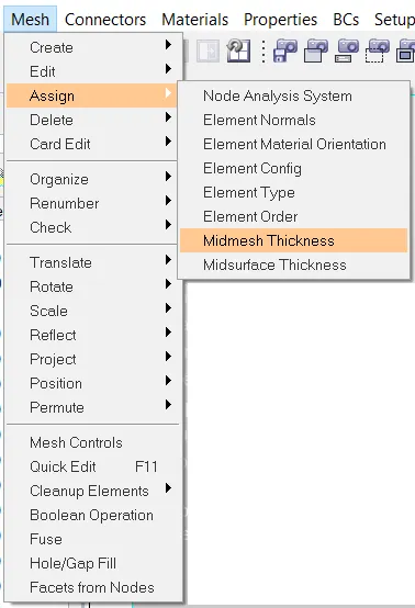
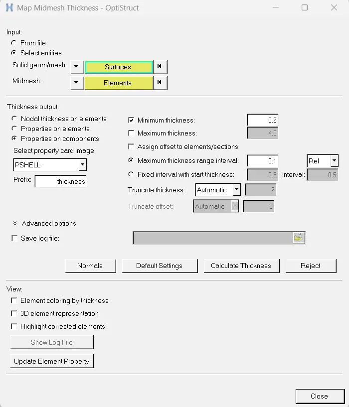
> Element represented in 2D detailed element representation..
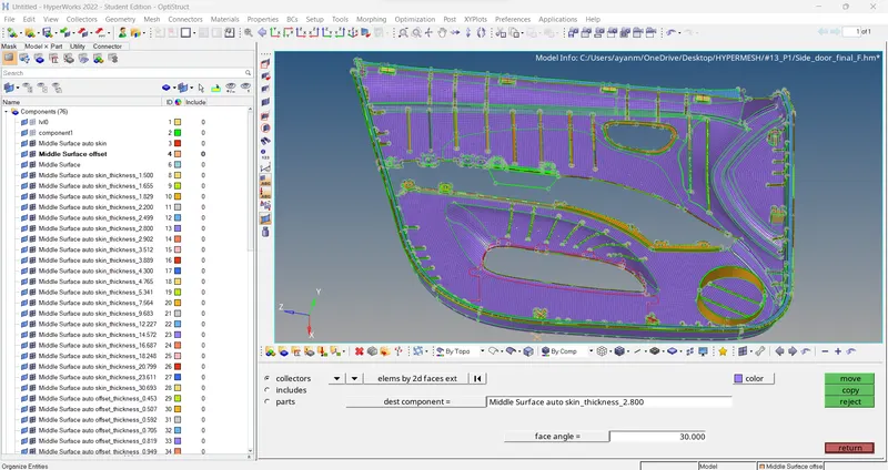
// Note: some Thickness are wrongly done by software. so, we have to organize that region thickness by manually with average thickness of that region in plastic non-uniform component like this.
> to do that go to Tool > organize > elements > dest. component > move.

//
-- Final checks >>
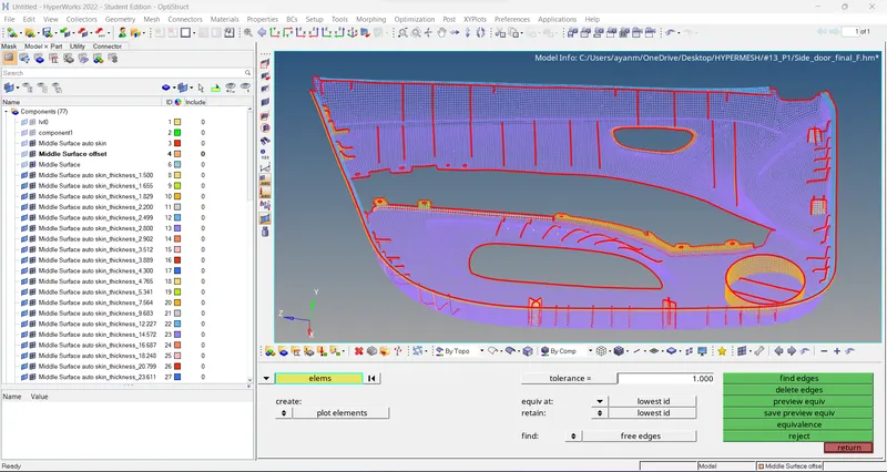
- EDGES check >
Edges check is done to ensure the connectivity of the elements is present.
Go to Tool > edges > elements(displayed) > find edges.
- Normal check >
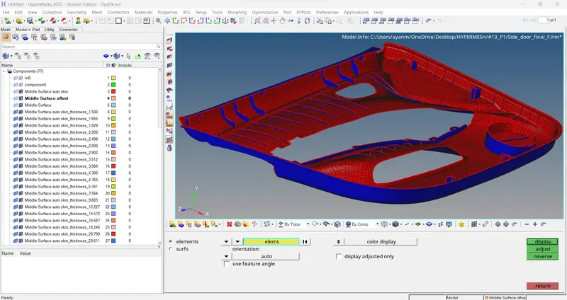
Normal check is performed to check the direction of the vector consistency of the geometry/Elements which directly affect the calculation of the physical quantity.
Go to Tool > normals > display. (adjust)
- Duplicate check >
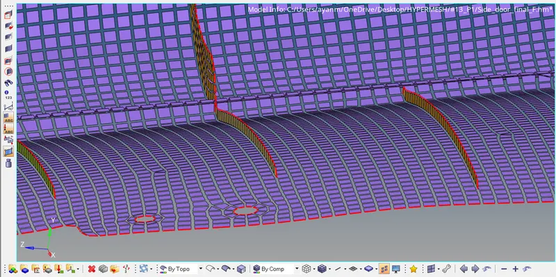
To check any duplicate elements are present in the model.
To do that tools panel shrink elements & analysis manually if there any duplicate elements present.
FINAL VIEW -
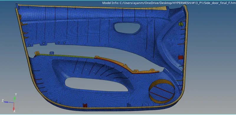
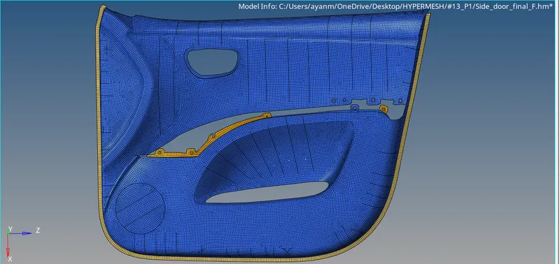
> without Thickness
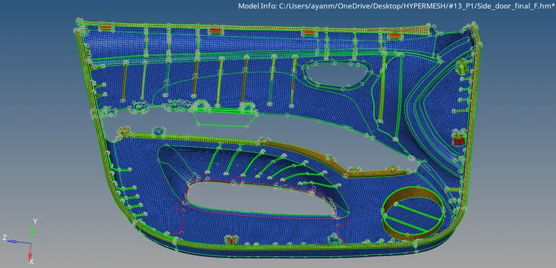
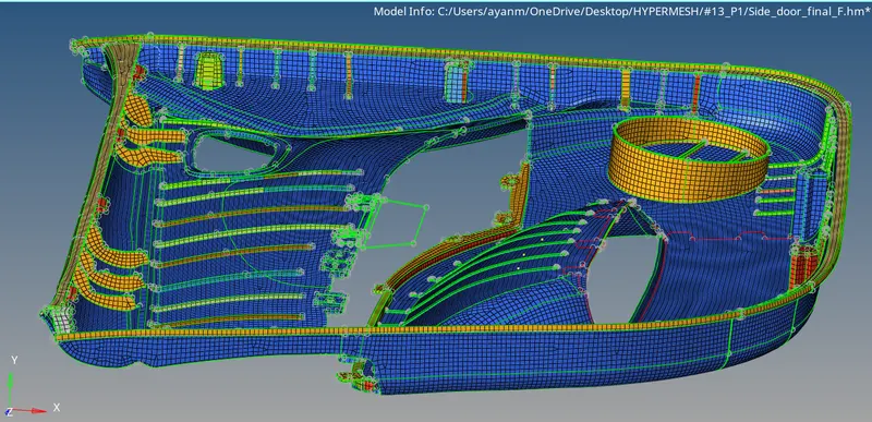
> with Thickness..
Learning Outcomes:
- Able to do geometry clean-up with no errors.
- Able to generate mid surface for complex geometry.
- Aware of all the quality criteria’s and quality parameters during mesh generation.
- Understood mesh generation and implemented mesh generation for complex geometry.
- Learned how to improve mesh flow, remove off elements and remove trias to achieve better mesh flow.
- Assigned thickness for all the features.
CONCLUSIONs:
For the given model mid surface is extracted and mesh is generated with in the given quality criteria. And all elements pass all the given quality parameters.
Also assigning thickness for FE to match with given component.