Week 12:Project-1-Meshing of Door Inner Panel Challenge
Aim:
To generate a mid surface and to mesh the Door Inner panel.
Objective:
- Import geometry to HyperMesh software.
- Generating mid-surface.
- Generate mesh
- Clean up the mesh as per the quality criteria.
- Create property cards and assign thickness.
Procedure:
1. A New Radioss file was created in Hypermesh and the Model was imported By Import option in the geometry pannel.
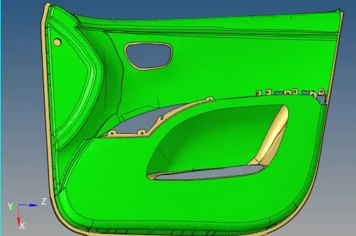
image 1 - Original CAD
2.The Given model/component has been checked each face to create the midsurface.
3. Mid surface created Manually for each Body seperately using Offset option In Surface edit pannel.
4.As the given geometry is a plastic component midsurface was generated with the help of offset+plane+sweep option,
upon further investigation it was observed that all the components were not captured correctly so for those components
midsurface was generated via Manual midsurfacing using Geom--> Surface Edit --> offset command.

image 2 - offset command
5. Geometry clean up was performed both automatically and manually in Mid surfaces.
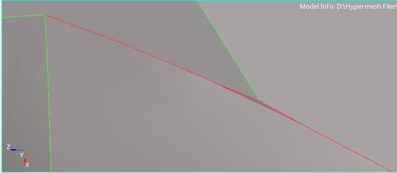
image 3 geometry cleanup before
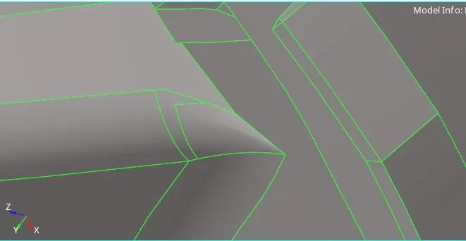
image 4 geometry cleanup after
6. The ribs area were selected according to their surface
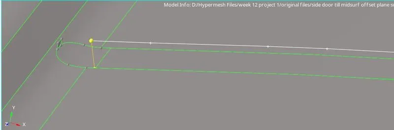
image 5 - Rib Creation before
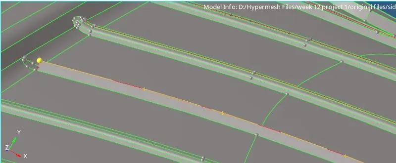
image 6 - Rib Creation after
7. Manual midsurface was created for each ribs and solids by using offset or translate option in tool panel.
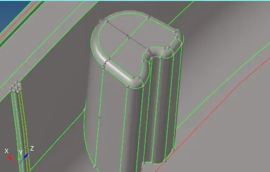
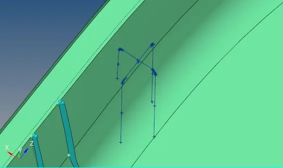
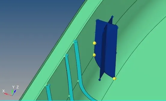
image 7 - Solid Capture
8. Then the created midsurf of each ribs were attached to the surface of parent grometry
9. First every ribs were attached to the surface by extending it to the parent geometry by using
Geometry> surface edit > Extend option.
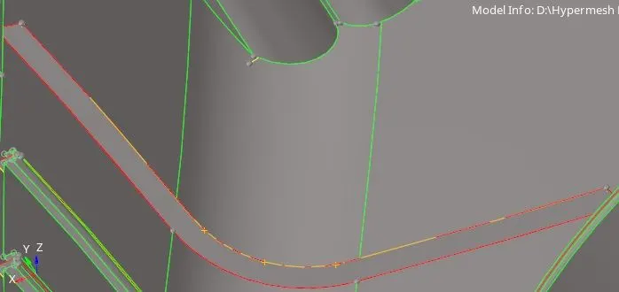
image 8 Surface extension before
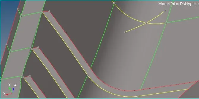
image 9 - Surface extension after
10. After extending the midsurf of rib which was extended over the parent surface was trimmed by using
Geometry > surface edit >trim with line /trim with surf option.
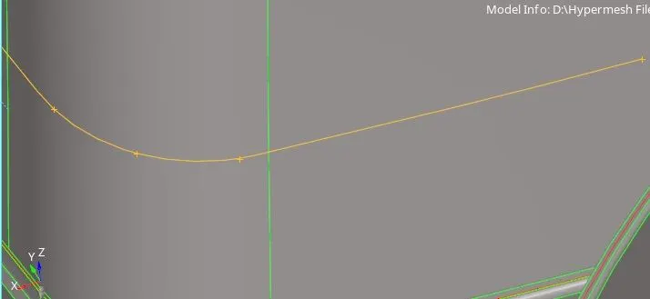
image 10 - Surface trim before
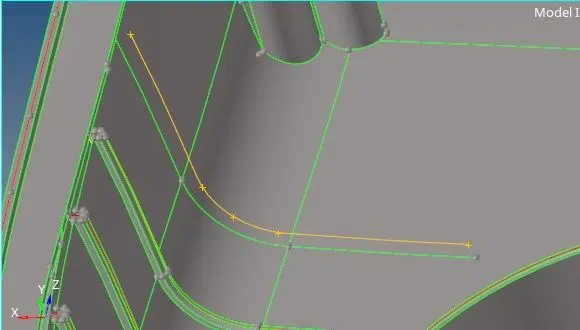
image 11 - Surface trim after
11. The 2D mesh was generated in the midsurface of the given component.The generated midsurface was assymetrical .
12. So that the mesh could be generated by selecting every surface.
13. Target elemnt size and other quality conditions were given in The check elements dialouge box(F10)
14. By checking elements value which given in check elements panel,if any elements fails ,the failed elements were corrected by using remesh or cleanup tools in quality index panel.
15. Check the connectivity of the mesh on ribs with mesh on surface if there is free edges present then clear it by using mesh edit option.
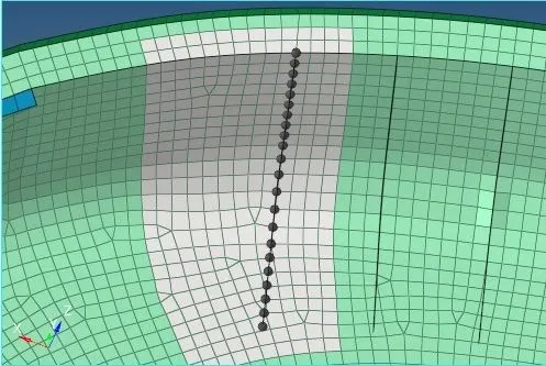
image 12 - disjoint mesh
As shown above there is no connectivity between two mesh surfaces.
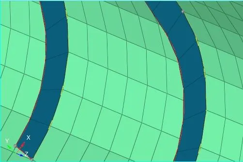
image 13 - mesh imprint
16. The various midsurfaces are extracted into separate collector as per their thickness and assign their thickness in property tab as shown
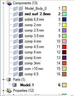
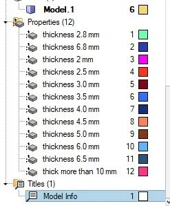
image 14 Asigning thickness for various components
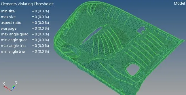
image 15 Element quality final model
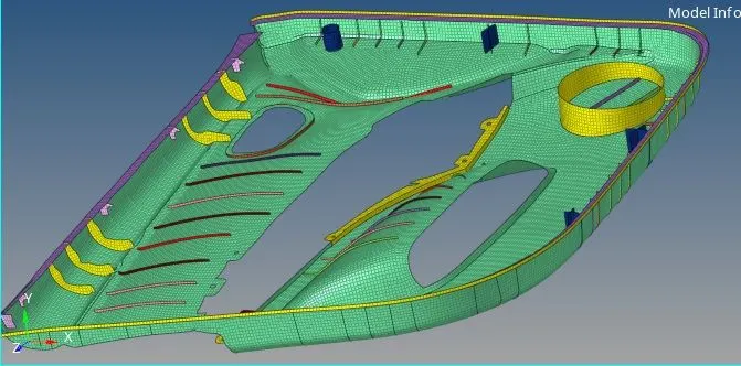
image 16 Final model
Finally we turn on 3D representation of 2D elements and check how well the mesh is captured.
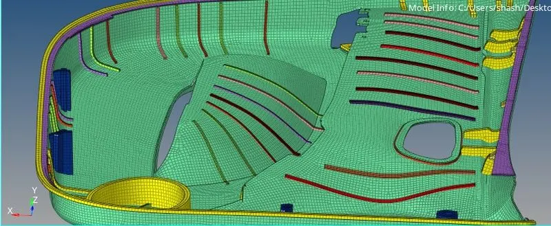
image 17 Final model 3D representation
Result : The following component is meshed as per required quality criteria.
The generated mesh is checked for quality criteria and topology capture.