Aim:
To create the shell (2-D) meshing for the car side door panel by eliminating geometrical errors and considering the given quality criteria using Hypermesh .
Introduction:
Side door panel:
Side door panel is the plastic part, materials used for the door panelare acrylonitrile-butadiene-styrene (ABS), polycarbonate alloys, polypropylene.
Properties:
- High strength and toughness.
- Good heat resistance.
- Good impact resistance.
- Good processing characteristics.
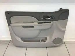
Fig1.1: Side door inner panel.
For user defined Quality criteria refer table1.1:
Target Element Length = 4 Units
| Sr. No. |
Quality Criteria |
Value |
| 1 |
Aspect Ratio |
5 |
| 2 |
Skewness |
45 |
| 3 |
Warping |
15 |
| 4 |
Taper |
0.5 |
| 5 |
Min. Length |
2 Units |
| 6 |
Max. Length |
6 Units |
| 7 |
Min angle Quad |
45 |
| 8 |
Max angle Quad |
135 |
| 9 |
Min angle Tria |
20 |
| 10 |
Max angle Tria |
120 |
| 11 |
Tria % |
10 |
Table1.1: Quality criteria for meshing.
Procedure:
01. CAD geometry clean up and topology.
02. Defeaturing.
03. Mid-surface extraction.
04. Shell meshing.
05. Creating properties and assigning thicknesses.
One by one we will study the above steps in detail.
01.
CAD geometry clean up and topology:
In this step the given model undergoes geometry check, where all the defects such as collapsed faces, cracks, free edges and T-edges are cleared.
Tools used for topology clean up:
Tools > Edge Edit panel
A. Equivalence (multiple edges at a time) Search surfaces for pairs of free edges and combine into shared edges.
B. Toggle (edge pair at a time) Select an edge; equivalences with other free edges found within a user specified tolerance.
C. Replace (one edge pair at a time) Select two edges to equivalence together. Control which edge to retain and which to move.
D. Geom => Surfaces => Ruled or Geom => Quick edit => filler surface or 2D => spline => surfaces only (to create missing surfaces).
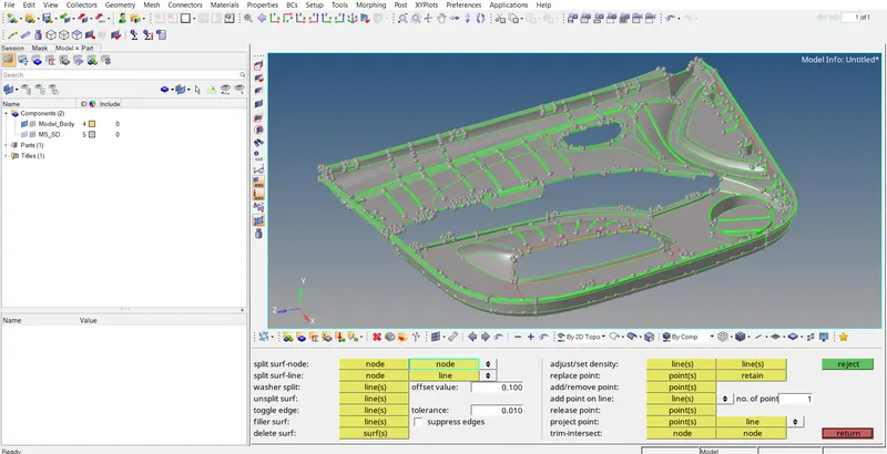
Fig1.2: Quick edit tools (panel) for geometry cleanup.
E. Fill missing surfaces using line drag:
Use the Drag along the line subpanel to create surfaces by dragging lines or a node list along another line, called the 'drag line'.
Follow following steps for dragging:
- Select the lines or node list to drag.
- Select the lines that the drag will follow. This can also be the series of connected lines.
- Merge the input lines into smooth lines when possible and create the surface for each group that forms a tangentially continuous line. Clear this checkbox to create a surface for each input line, with shared edges connecting surfaces where relevant.
- Choose where to organize the resulting surface component.
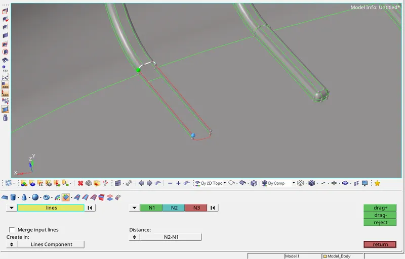
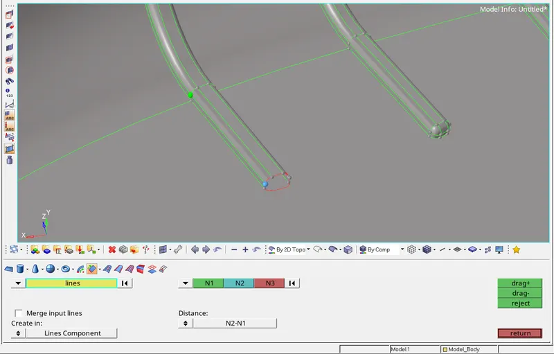
Fig1.3: Creating missing surfaces using drag command.
02.
Defeaturing:
A. Geom => Defeature => surface fillets.
B. Use the surf fillet subpanel to identify and remove surface fillets (curved surfaces that creates a smooth transition between relatively perpendicular geometric entities). You can identify fillets based on radius, because fillets are always uniform arcs. You can also select a fillet by picking one of the edges that it connects. Once found, fillets can be removed using tools that display automatically after the find process.
C. By clicking on remove all selected fillets we can remove the fillets.
Tools used for Defeaturing:
A.
Toggle edge
Left-click a free edge (red) to make it shared (green) or a shared edge to make it supressed (blue).
Right click a supressed edge to make it shared or a shared edge to make it free.
In either case, the edge must meet the criteria for the type of edge you wish to change it to. For example, toggling a free edge to a shared edge tequires a presence of a similar edge within the distance you specify in the tolerance field.
B.
Replace (one edge pair at a time) Select two edges for equivalence together.
Control which edge to retain and which one to move.
C.
Geom => Quick edit => Filler surface (to create the missing surfaces).
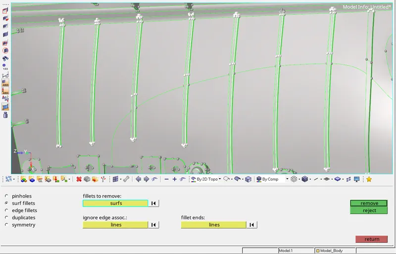
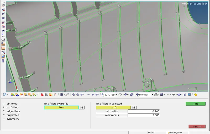
Fig1.4: Removing surface fillets using defeature command.
03.
Mid-surface extraction:
The given model is a side door panel and before going to the Mid surface extraction check for thickness of entities and measure (Geom => distance). We found different thickness on each feature. For the parent component we have thickness (T) is 2.8 units.
Mid surface is done by manually using offset (Geom => surface edit => offset).
Steps followed for offseting surfaces:
- Select offset.
- Offset moves the selected surfaces without retaining their connections to surrounding geometry.
- Select the surface and make a duplicate of same surface.
- Input the value which is half of the thickness.
- To check the direction click on vector normal so that we can see the offset direction, also one can change the direction by reverse normal.
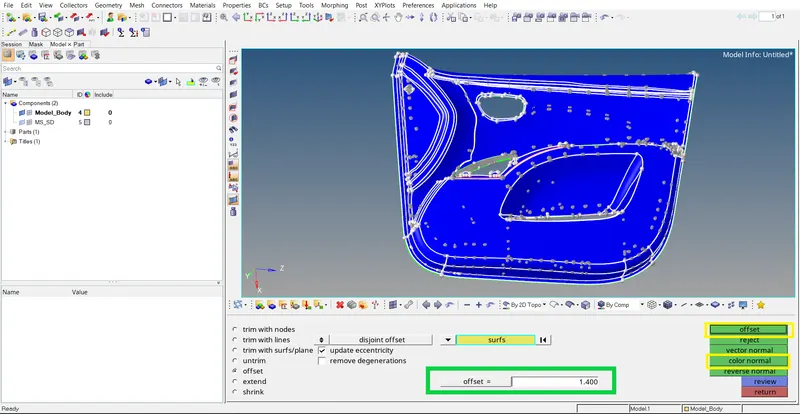
Fig1.5: Extracting mid-surface using offset command on A-surface.
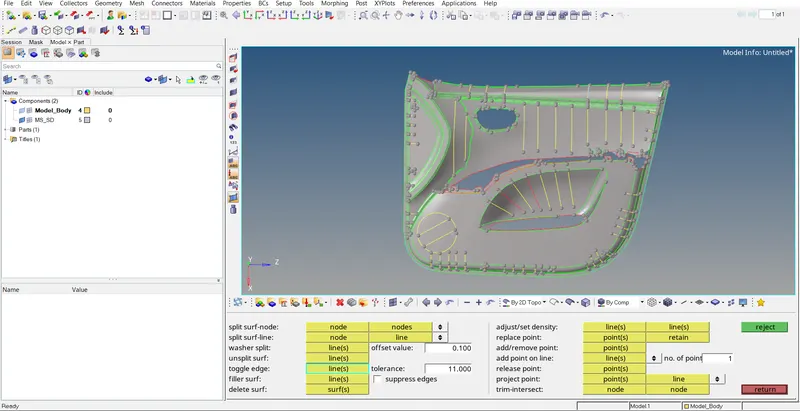
Fig1.6: Extracted mid-surface using offset command.
Offset:
For all ribs extraction of mid one file final edit tool from Midsurface.
(Geom => midsurface => final edit tool).
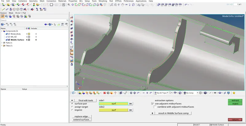
Fig1.7: Extracted mid-surface using final edit tool.
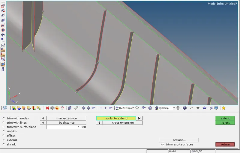
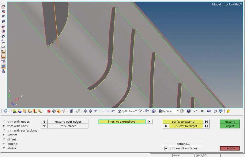
Steps followed for executing of extend command:
- Select a surface.
- Extend all the ribs to the base surface using extend.
- Select the line to extend a surface over edges to another surface.
- Select the target surface.
Fig1.8: Extracted mid-surface is extended to the base surface in order to enhance the connectivity of elements.
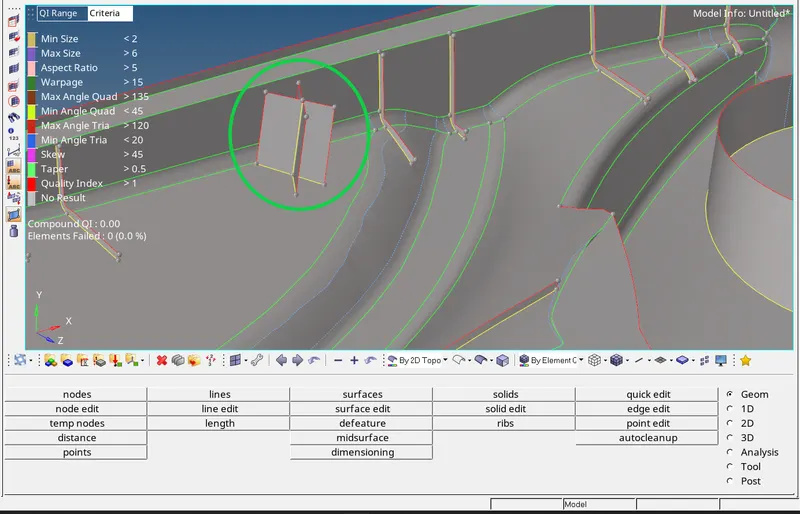
Fig1.9: Extracted mid-surface for representation of doghouses.
04.
Shell meshing:
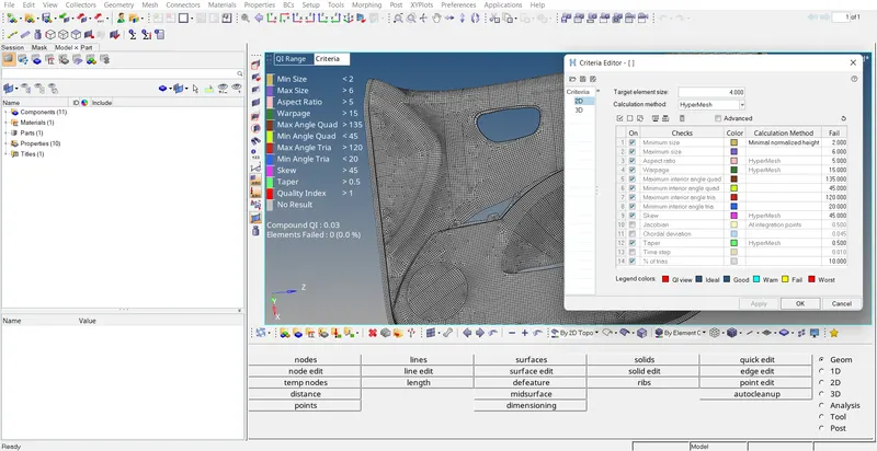
Before meshing assign the given element quality criteria into hypermesh.
For assigning quality criteria:
Go to => Preferences => Criteria file setting.
Fig1.10: Defining the quality criteria for creating mesh of the specified quality.
Start meshing process by Automesh (2D-Automesh)
Steps for meshing:
A.
Select surfaces for initial mesh and for remesh select elements.
B.
Select mesh size which is Target/Average length 5 units. Use the size and bias subpanel to perform size and bias meshing, a flexible and powerful meshing method.
A minimum of inputs are required for the element criteria settingsettings. The algorithm options set preferences on how to handle certain situations when encountered in the geometry. When using existing finite elements as basis for mesh generationgeneration, feature recognition settings allows mesher to break up the are as defined by the selected elements into logical groupings boundary with mesh control set for each group boundary.
C.
Select the type of mesh as 'mixed' (Quad, Tria, Mixed, R tria, etc) and click on alin and size in order to get proper mesh near features.
Click on 'mesh' or middle mouse button.
Modify mesh flow by changing surfaces to elements and select the elements. Make sure that while meshing all the quality criteria must be satisfied. Avoid opposite trias, trias touching each other, trias on free edges and rotational quads.
Remove all the failing elements by using cleanup tools.
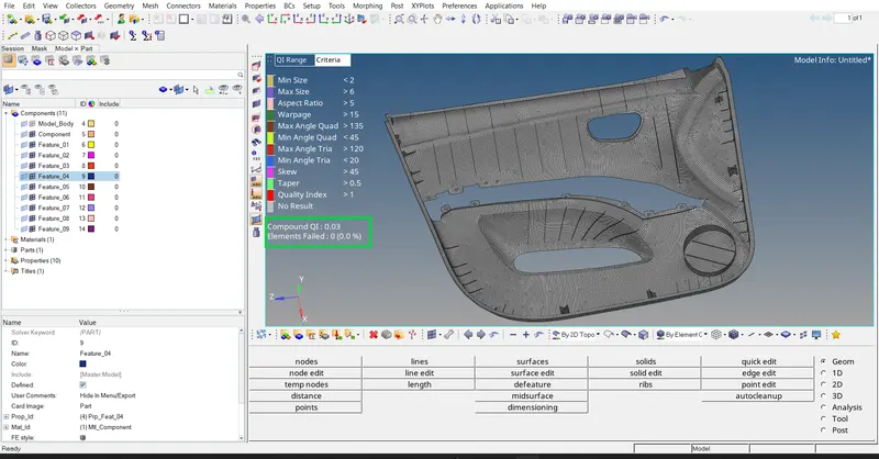
We can see zero elements are failing.
Fig1.11: Mesh for the given component as per specified quality criteria.
05.
Creating properties and assigning thicknesses:
Not only property we can create components, materials, cross sections, etc.
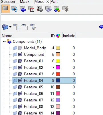
Brfore creating properties we need to create components for elements as per the different thickness.
Right click on the tab area and select components to create components.
Fig1.12: Components defining different features and surfaces of the geometry.
If thickness varies then divide that region w. r. t. mesh flow and assign thickness value from maximum to minimum with equal intervals.
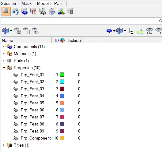
Create properties as per components and their thicknesses. To create right click on the Tab area and select property to create properties.
A.
Select property, we can see the properties in the tab area.
B.
Click on the property and rename, change thickness, select material, card image, etc.
For each component we need to create property as shown in fig
Assign properties to each component by right click on the comp => assign => select property.
Fig1.13: Properties defining different thicknesses of different features and surfaces of the geometry.
Find free edges:
Use the edges panel to find the free edges in a group of shell elements, find the T-connections in a group of shell elements. Free edges are defined as a pair of nodes identifying an elemwnt edge that is not shared with another element. Free edges are normally found around the outer perimeter of the part or around the openings of the part.
Free edges found in your model are displayed as red plot elements in their own component called edges. Free edges within a field of elements typically indicate a discontinuity within the meah. Such discontinuities may be intentionalintentional, such as crack modeling for durability simulation or unintentional due to geometrical discontinuities, meshing methods or component boundaries. In cases where a mesh has a discontinuity, there will typically be more than one node at approximately the same location in space.
Such nodes are called as 'coincident'.
You can use equivalence to remove the coincident nodes, based on a search tolerance that you specify.
Steps
A.
Goto => tools => edge
B.
Select the elements those are associated with edges you wish to find.
C.
Specify a spherical search radius around each node in the selected component or group of elements. If multiple nodes are found within search tolerance they are considered coincident and can be reaolved with the equivalence function. Tolerance is 60% to 70% of the thickness.
D.
Click on a preview equivalence and equivalence to join nodes.
E.
Click on find edges to see the free edges in red colour for mesh.
Check for normals:
Use the normal panel to display and reverse the normals of elements or surfaces. The orientation of element normals can also be adjusted. The normal of an element is determined by following the order of nodes of the elements using the right hand rule.
Steps:
A.
Use the elements subpanel to display and reverse the normals of elements. Select elements indirectly by components or directly by elementselements or elect to have all of the displayed 2D elements selected automatically. Click display to review the current normal orientation of the selected elements. Optionally, click reverse to flip the normals to the opposite sides.
B. Adjust the normals based on the orientation method you specified.
C. Flip all of the normals of the selected elements.
Result:
Shell (2D) mesh is done successfully for side door panel model by eliminating geometrical errors and considering specified quality criteria also assigning the thicknesses using hypermesh.