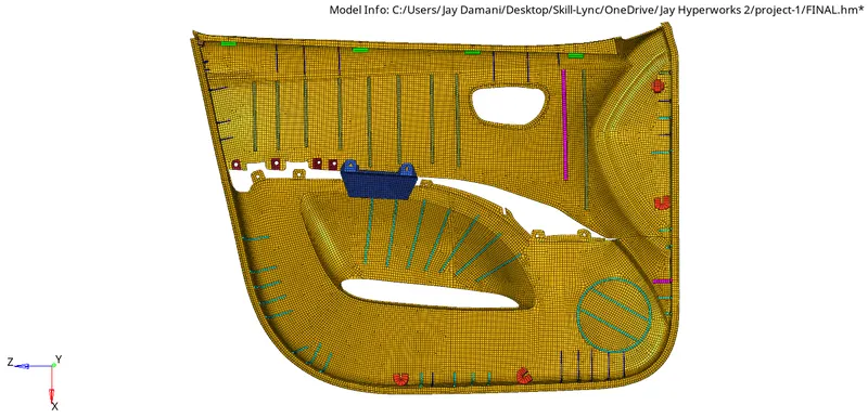
Week 12:Project-1-Meshing of Door Inner Panel Challenge
Problem Statement:
For the given component, perform mid-surfacing and mesh with the given element Quality criteria. After meshing the component, assign the thickness.
Theory:
The given part is an automobile's plastic door trim which latches onto the door's metal frame and lies on the interior.
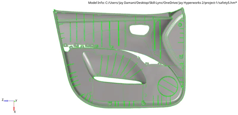
It is manufactured using processes such as blow molding, injection molding, compression molding, thermoforming, etc. Materials used can be ABS, LDPE, etc. These processes and materials allow the part to have varying thickness across all its dimensions. For most components, an average thickness is assumed while obtaining the mid-surface shell of such components.
Procedure:
Following are the steps involved to achieve the objective -
1) Import CAD Geometry - The part file should be of a format supported by Hyperworks (STP., IGES., STEP., etc.).
2) Geometry Cleanup - Most geometries when imported contain their surface & connectivity information which helps hypermesh. Still, sometimes the following errors can occur -
a. ill-defined surfaces
b. unconnected adjacent surfaces
c. duplicate surfaces
d. missing surfaces
The goal of geometry clean-up or topology repair is the restoration of surface data to a perfectly clean representation of the part. The unconnected adjacent surface can be identified by 'red edge lines'. When two adjacent surfaces are well-connected they are represented by a 'green edge line'. Such edges can be dealt with by using the 'Quick edit-toggle edges' function under the 'Geo' tab. The tolerance value should be according to the gap value across which we are trying to stitch the two surfaces. If a surface is missing in the middle of adjacent surfaces which is characterized by an area surrounded by red edges, the 'quick edit - filler surf' function can be used to automatically create the missing surfaces. Unnecessary split lines in the middle of a surface can ruin the mesh flow. so once the filler surfaces is created, its edges can be toggled which can be identified by a blue dotted line.
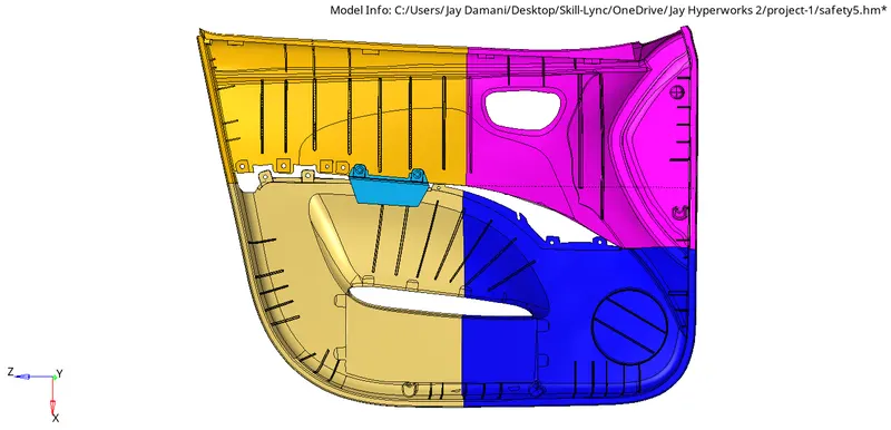
Since this is a single huge component, divide it into four parts to make visualization and working on the model simpler.
3) Mid-Surfacing - Plastic trims are intricate geometries and their varying thickness put the use of automatic mid-surfacing out of question. Different parts of such geometries have to be treated differently. Following are the ways of representing the various parts of such a geometry
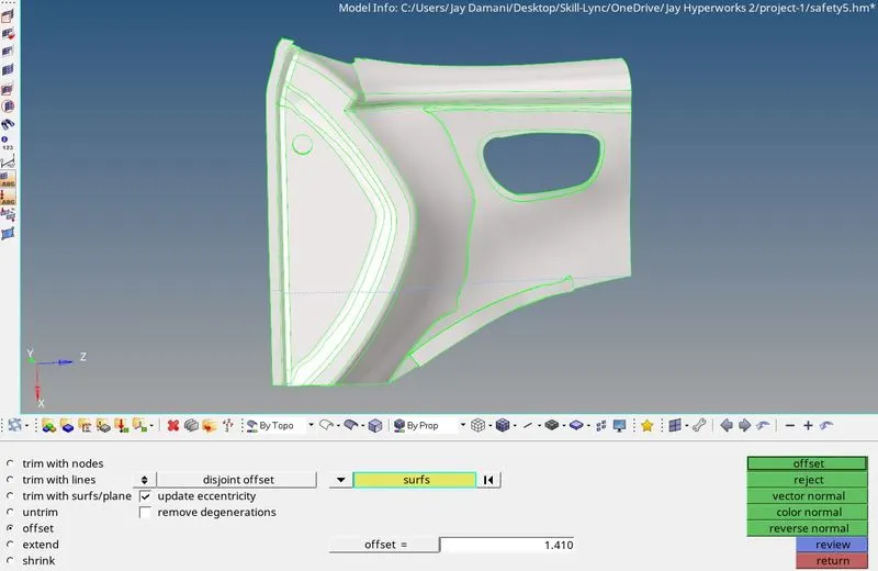
a) Main Plane - It is the base shape of the complete trim. All features lie over this. To obtain the midsurface we'll use the 'surface edit -> offset' function under the 'Geo' tab. The distance the surface needs to be offset can be determined by using the 'distance -> two points' function under the 'Geo' tab. Once the surface to be offset is selected, we need to duplicate it from the sub-menu and offset this duplicate surface to a distance equal to half of the thickness.
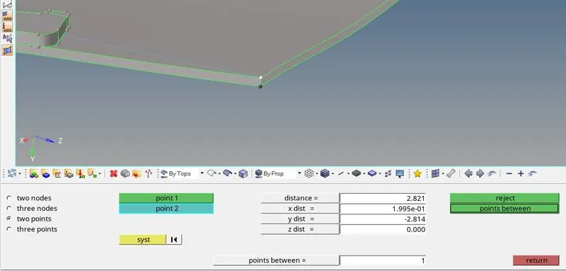

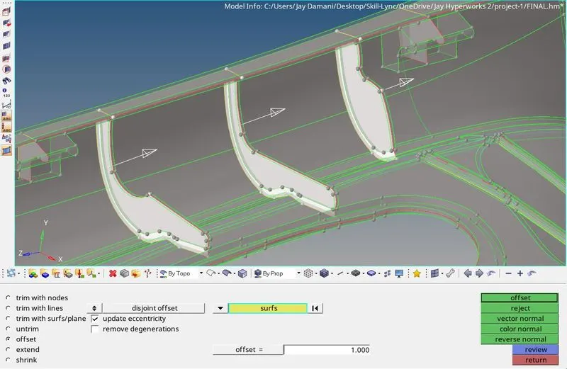
b) Ribs - Their main purpose is to provide strength. These are located at strategic locations since plastics are very elastic in nature till one point and they break if they flexed beyond a certain point. The strength also improves the consumer experience. Hence, modeling them properly is important while conducting strength studies. To obtain the midsurface we'll use the 'surface edit -> offset' function under the 'Geo' tab. The distance the surface needs to be offset can be determined by using the 'distance -> two points' function under the 'Geo' tab. Once the surface to be offset is selected, we need to duplicate it from the sub-menu and offset this duplicate surface to a distance equal to half of the thickness.
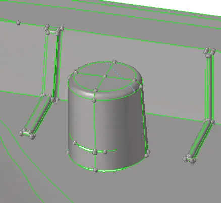
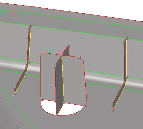
c) Boss - The boss helps to locate the part while fitting together with other plastic trims or metal parts of the main chassis. Since these parts usually have wide variations in thickness or are 3D solid, they can be captured into a 2D shell using no particular method. The location and volume are the most important here and not just the thickness or form.
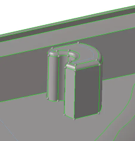
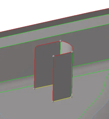
4) Meshing -
a) Now that we are all set for meshing, we firstly select an area to start from. A good practice would be to move from the middle of the part towards the outer edges. This leaves some flexibility for rearrangements while in the other case, the area becomes constrained by the surrounding mesh. Element type and size are set to 'mixed' and '4' respectively.
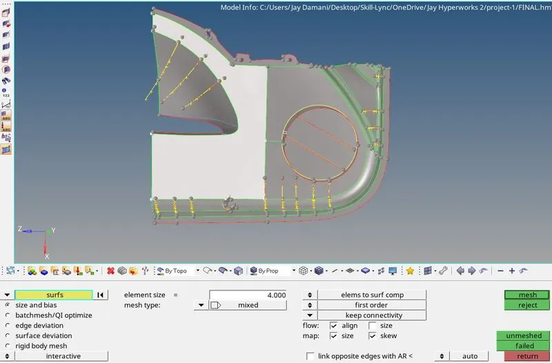
b) Larger areas should be sub-divided by creating split lines. This helps better regulate mesh quality. Small changes to the mesh's flow and arrangement can be made by altering the number of nodes on each edge. If this does not suffice, the function 'rebuild mesh' under the '2D' tab can help improve the mesh. Firstly the mesh criteria have to be set to the given mesh quality parameters after which the elements are selected which require betterment. Running this should output a mesh that fulfills all quality criteria and maintains good mesh flow.
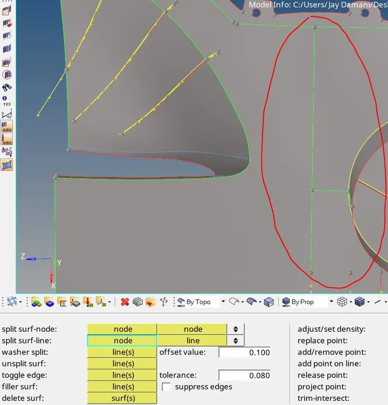
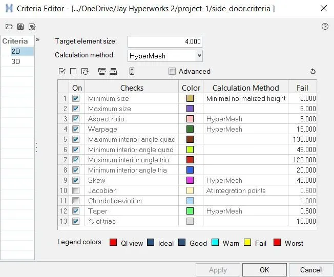
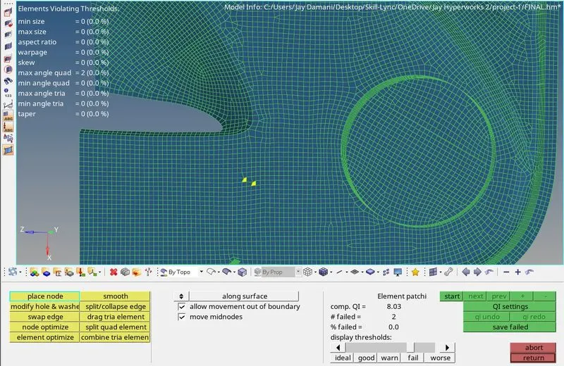
c) Further changes can be made to the mesh using the 'quality index' function under the '2D' tab. This checks all elements in the model for quality errors and provides to cleanup any such errors. Cleanup tools such as 'smooth' and 'element optimize' automatically make minor adjustments to the mesh to improve flow and adjust elements to clear quality criteria. Others such as 'place node', 'drag tria elements', 'combine tria elements', etc. allow for manual changes to the mesh.
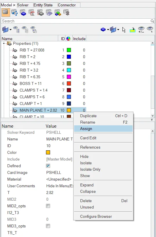
5) Thickness Assignment - The property cards allow us to define the type of elements in the parts wiz. 2D shells in our case hence we'll be using the property 'PSHELL'. Here we also input the thickness of the part. These property cards are then assigned to the respective elements as per the part they represent.
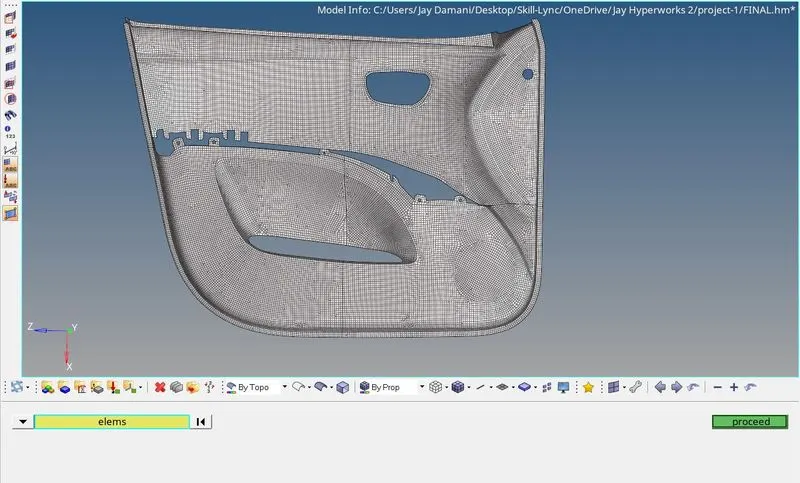
Final CAD Image -