Week 12:Project-1-Meshing of Door Inner Panel Challenge
AIM: To extract the mid surfacesof the side door component and to mesh with the proper thickness following the quality criteria parameters
PROCEDURE:
- initially check the component in all the views, get to know the attachments,etc
- as it is a plastic components it will have varing thickness so observe the component carefully
- find the widths of the edges, which are of varing and complex shapes
MIDSURFACE:
- It is a complex shape,so check for all the midsurface, extraction options like,
- skin offset
- offset+planes+offset
- plane offset
- take the most accurate, midsuface creation, as it has many curvatures, complex shapes HYPERMESH may mis s or excludes some of thr shapes
- it the above methods are not usefull, use MANUAL method, as it is a very accurate methos
- we can even, do both practices
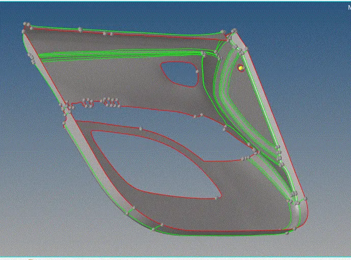
- this is the base mid extracted, given by HYPERMESH which have excluded all the complex fixtures in the component
lets, go to manual mid surface creation for all the complex shapes
- the fixtures are to be extracted and extendes to the midsurface, this can e done by two methods
- by MIDLINE METHID
- SURFACE OFFSET method
midline method is mostly, applicane for the components have waring thickness, by using the mis line method we create a immaginary midline which, we use it to create the surface
surface offset if preferbe for, uniform thick ness one,
we are to following both for the , fixturex/rib ectraction
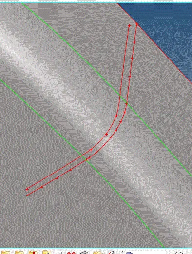
MID LINE method:
- create a mid line and project it on to the attached surface
- combine the created line as single individual lines
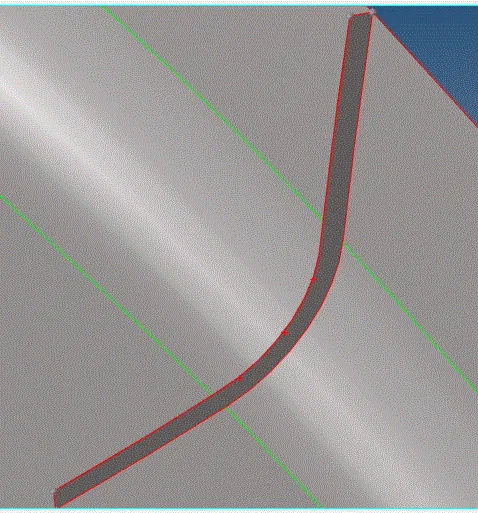
- SURFACES>RULED>CEATE
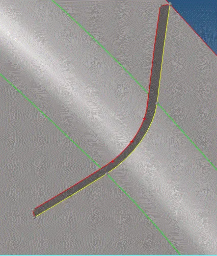
- SURFACE EDIT> EXTENT> from surface and--- to surface with the extending edge are to be selected
- extend , a yellow coloured lines shows that ot has extended
OFFSET METHOD:
- select the side / surface which is to be offset
- duplicate it and offset to the middle distance
- aftercreation, extend it to the base mid surface
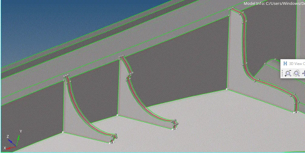
- red coloured line shows the creation of mid surface
- we can visualize it by changing the transprancy of the components
- these are to ve extended to the midsurface
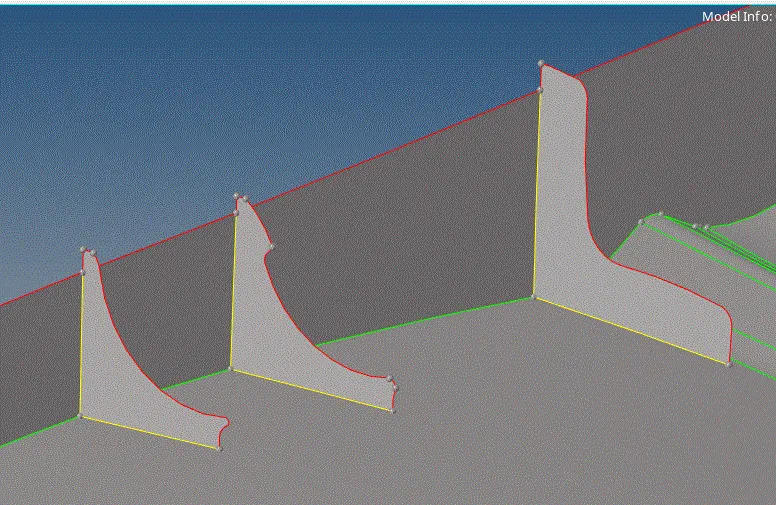
- simillarly created all other ribs
- not only these two methods but, we have to use different new methods for mid surface creation of the fixtures
- we are to be using,replace point, toggle, project ppoint, inset point on lines for the creation of lines ets
- replace point is one of the most usable tools, which helps to replace point yo sedired point, which also changes the shapes
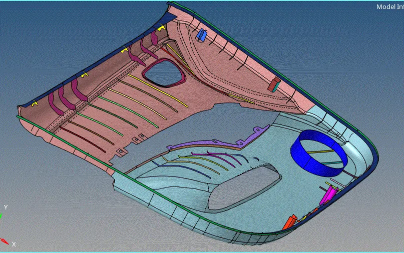
simillaRLY, CREATE and set all the extracred midsurfaces, in the assigned components , set different colours fof better visualzation and understanding
the entire extractedmissurface is as shown
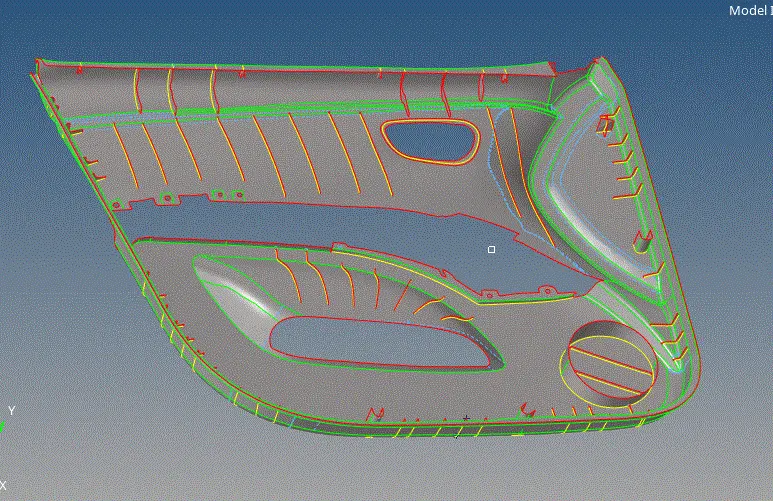
there are to assigne in different components,with assigned names
MESHING:
- This can be done by two ways,
- components by components
- at once
as it is having a lot of extebded cures,going pary by part may compramise the edge cinnectivity, so, i have prefered the layer, meshing the component at once
example: we have meshed base first and then we have done the ribs then there is ni connectivity between them which takes time for stiching the elements
- set in the meshing parametrs and start meshing
NOTE: we can also follow the batch meshing process, but the created mid surface and mesh are very disturbed leaving th lot of qualitu errors
- mesh the components
- correct all te errors by, rebuilding, smooting and tria drad'
- mesh can be done with out errors but to maintai the mesh flow is important
- toggele the reqiured lines, check by trail and error methods
- because mesh will be created by toggeling all the feature and construction lines, but the formed elements loode the bade shape of the componet
- also it effects the mesh flow
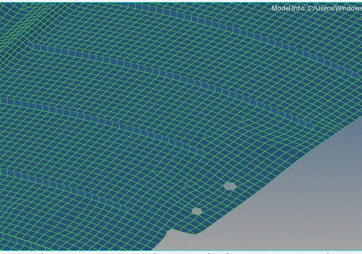
- remove the tria elememts to the maxium extend,
- drab them combine them or re build the mesh so as to maintain the good mesh flow
- don't entirly remove the trias, we have to use them as the critical areas ehere quads are impossibe
- correct the mesh to the maxium
- the entire mesh is asshown
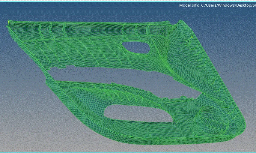
- there will be still errors at the extending or intersecting lines(yellow lines) this will raise due to the poor extebding of thr rib surfaces
- this can be clearedby replace points option
FREE EDGES:
- if your components comtain free edges it is not a very good practice, we have to create a goo connecting mesg
- if there are free edges then it leades to the element breakage while testing
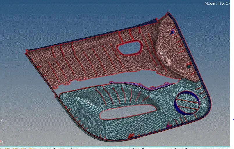
- there will be duplicate elements formed while making corrections in the mesh , find them and delete them, generally these are seen at free edge testing if not visuble change view to grid and see
- delete all the mid lines , constrction loines that are created
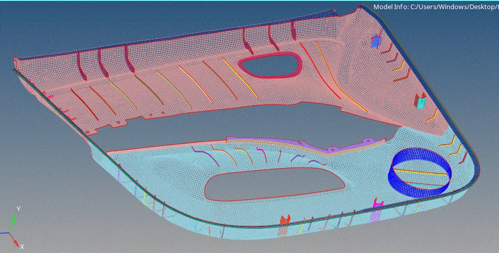
thickness assignng:
- create properties for all the components with the assigning thickines
- here i have assigned same material for all the components
- for th dog houses and mountngs, assign the near by rib thickness
CONCLUSION:
- i have tried a lot of methods, tries each possible method of mid surface extraction
- tried different ways of meshing,realized the future possible errors and changed the meshing methods
- how to create good mesh flow, reduce trias
- where to give construction lines for mesh and where not to