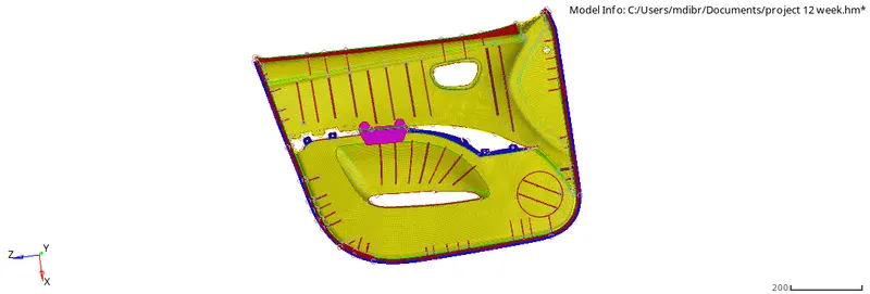
Week 12:Project-1-Meshing of Door Inner Panel Challenge
AIM:To mesh the given side-door panel plastic component by the following quality criteria and assign thickness.
Target Element Length = 4mm
S.N Quality Criteria Value
1 Aspect Ratio 5
2 Skewness 45
3 Warping 15
4 Taper 0.5
5 Min. Length 2mm
6 Max. Length 6mm
7 Min angle Quad 45
8 Max angle Quad 135
9 Min angle Tria 20
10 Max angle Tria 120
10 Tria % 10
OBJECTIVE:
1. To geometrically clean the given surface for any errors in it.
2.To extract a proper midsurface for the component.
3.To clean the midsurface so as to avoid any minimum length errors in it.
4.To mesh the component with minimum number of tria elements and cleaning all the quality crieteria set for the model.
5.To assign thickness to the various parts in the model.
PROCEDURE:
STEP 1 :- Component Study
- Its a car's inner side door panel.
- The given component is a plastic component. So it will be having varying thickness.
- The main part of the component is of 2.8 thickness.
- The rest part is consisting of many ribs and features.
- Ribs are given to increase the strength of the component.
- There is also a circular part where the speakers will be placed.
- While going through the parent geometry we can see that there are many deformations formed while importing the geometry to hypermesh.
STEP 2: Opening the File:
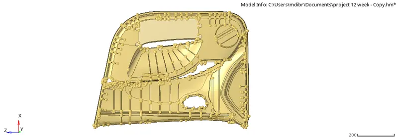
-The File given is a ‘.hm’ File. It can be opened directly by following the steps.
-open the downloaded file.
-after opening the file to view the model click f key.
-Change the mode to topo.
STEP 3: Geometry cleanup:
-After importing the model we can Check for deformation.
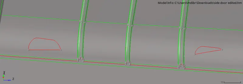
a) We can easily fix this by using Filler Surface.
b) Go to Quick Edit in Geometry.
c) Use Filler Surf tool click on the boundary of the gap. Then you can see the gap is filled and the boundary of the gap will be toggled.
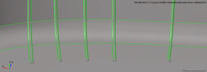
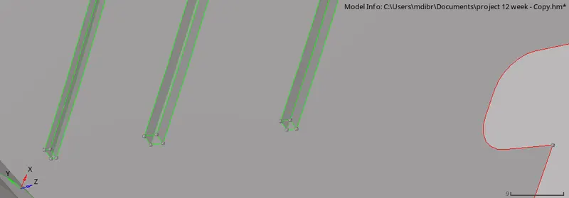
-While taking the Ribs we can see that all the ribs are having fillets at there edges. When taking the midsurface of these Ribs it will be a problem.
-So for a better mid surface creation we will defeature the surface fillets in the Ribs.
-For this we use the tool Defeature in geometry.
-In Defeature use Surface Fillets option.
-Use second option in that which is "Find Fillets in selected" under that choose surface.
-Give Minumum and maximum radius, fillets in between this range will be deleted.
-Click on Find.
-then the Hypermesh will show us the surface fillets between that range.
- From that we can choose the surface to be deleted under " fillets to remove"
-Also under that we can see an option "ignore edge association" which will help use to deselect some edges which was automatically selected by hypermesh which we really needed.
-Then click on remove so that we can remove the fillets and will get a good sharp edged ribs


STEP 4: Mid surface generation and its geometry cleanup of mid surface.
A. Auto mid-surface (Just for referance while making manual Mid-surface)
- There is Auto Midsurface option but we cannot use that in here because it will delete some features that we needed. But we can first create one to know about the shape which our manual mid surface will be almost be looking like.
-For Auto midsurface go to Geometry>Midsurface
-Go to extraction options then choose skin offset for better offset
-Then go back to auto extraction, Select the parent surface body which we want to create auto mid surface. Duplicate it. Then click on extract.
-After sometime we get the auto midsurface
B. Manual mid surfaceing1
-This component is a plastic component so it will be having varying thickness.
-So we need to check the thickness of each part seperately.
-Checking thickness at the edges will be easy but checking thickness at area exept the sides is difficult so we can to one thing.
-Create temp nodes (Shift+F2) on both sides of a place of the parent surfaces.
-Then use distantce (f4), Two nodes option to measure, Thus we can measure the thickness of inside areas.
-After getting thickness we can start manual mid surfaceing. For manual mid surfaceing we will use the Offset in Surace edit option.
-Geometry>Surface Edit> Offset.
-In offset option choose continuous offset
-Then select the surface to be offseted
-Make duplicate of that surface. Then click on offset.
- While doing the manual mid-surface we cannot do the whole part in a single stretch. We need to do it part by part. but can almost do parts with same thickness at a single process.
-We can easily make the mid surface of the mainbody but for ribs it is a bit difficult because of the different shapes on both sides in some ribs
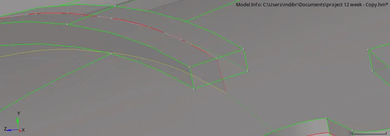
Middle line tool To Generate Midsurface for the Ribs
-First draw a middle line by using the edges of the parent rib.
-Geometry > lines> Midlines.
-Select one edge line on one line list and other edge line on other line list.
-Click on create.
-After Making the line we can project it to the below main midsurface.
-to project the line to the midsurface by Tools> Project>To surface
-Select the lines to project in Lines
-Select the surface to which the lines should be projected in To surface
- Select the direction in Along vector.
-Click on Project.
- Now we have 2 lines for a rib, above and below. Now we can make the mid surface of the rib by making a surface in between using the tool Ruled.
- Geometry> Surface > Ruled
- In the 1st line list Select the first set of lines and in second box choose second set of lines.
- Click on create.
Using Offset option
-This option can be used where the ribs are of equal thickness.
-Measure the thickness of the rib first.
-Then go to Geometry> surface edit > Offset.
- Select the surface to be offseted.
- Right click on surfaces option and make duplicate
-Give half the thickness of the rib in offest box.
-Click on vector normal to know the direction. If want to reverse click on reverse normal.
-Click on offset.
Cleaning up of the mid surface
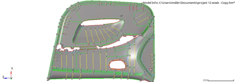
- Small gaps and unnecessary hole can be filled using Filler surface tool in quick edit
- Small deformations can be made good using Replace points in quick edit
-Lines which will be failing for minimum length error can be eliminated using toggle edge in quick edit.
-Proper connection shall be established between lines.
STEP 5: Setting up Quality criteria-
-For setting up the criterias as given the project we need to go to Criteria editor.
- For that go to Preferences> Criteria file settings
- In that tick in the boxes near which all the criteria we wanted and give the values for each criteria.
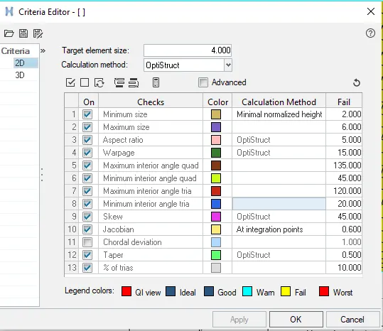
- Save the Criteria file so that we dont need to enter it each time.
- Click on Apply
-Click on Ok.
STEP 6:- Meshing:
- After setting up the Quality criteria we can start the meshing process.
- 2D> Automesh.
- After clicking on the surface box Select the surfaces needed to be meshed.
- Give element size as 4 as in the question
- Give the mesh type as Mixed.
- Elements to surface component is choosen to add the mesh to the surface component
- Keep connectivity is given to keep the mesh connectivity
- Check the Align and size to get a good mesh flow.
- Click on mesh.
- We can change the surface to elements and select the elements we want to remesh and click on Mesh to remesh the elements
- The mesh we get will have a huge number of trias, fixed trias and rotational quads. also the mesh flow wont be in a good pattern.
- Inorder to make it a good mesh. We will reduce the number of trias ( removing the unwanted trias)
- This can be achived be going to 2D> Quality Index> Cleanup tools.
- We can remove trias and get good mesh flow by using the cleanup tools
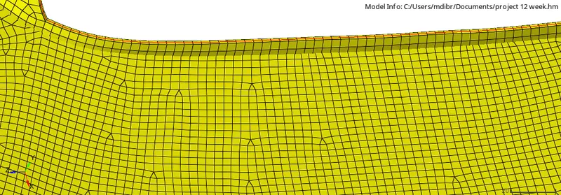

To check Free Edges:
-For checking normal we need to go to Tool> Edges
-Choose Elements> the select the whole elements.
-Click on Find edges.
-Now Hide other parts and Make edges mesh only visible.
-Now check if there is red line on any area which is not a boundary.
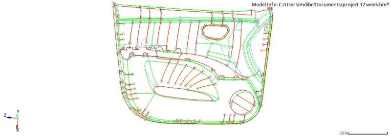

STEP 9: Assigning thickness
-After the whole meshing is done we can assigin thickness to the mesh inorder to make the 2dmesh exact as the real product.
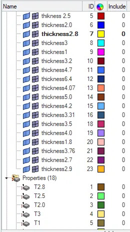
-First step for assigining thickness is to move parts with same thickness to the same component.
-To create a component . Right click on the Model view area> Create > component.
-Now rename the component with Thickness value for easy workflow.
-Move the parts to its assigned components based on the thickness.
-Tools> Organise> Collectors.
-Select elements and choose elements that we want to move.
-In destination component choose the component to where we want to move these elements.
-Click on move.
-After making the whole components, we need to make the properties for each thickness.
-To make property. Right click on Model view area > Create> Property.
-Rename the property with the thickness value.
-Also set the thickness of the property. By clicking on property we can see its details below.
- In that we can see a T which represents the thickness give the thickness value . Click on enter.
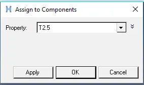
-To Apply the property to the Components. Right click on component
-Select assign. Choose the property of the component from the pop up dialogue box
-Click on Apply. Click on Ok.
-To see the mesh in 3D. Choose the 2D detailed element representsation.
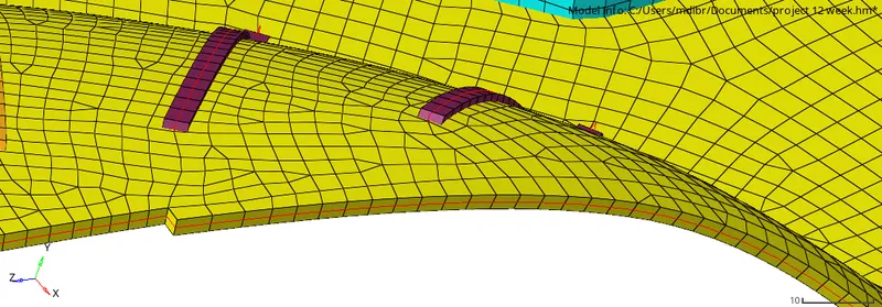
Final model image: