2D shell meshing of side door panel (plastic component) with varying thickness
Objective:
The objective of this project is to create a 2D mesh of a plastic component with varying thickness and assign thickness to the mesh accordingly. For this purpose, we are going to use the side door panel of a car.
For the mesh, the following quality criteria should be followed,
| S.N | Quality Criteria | Value |
| 1 | Target element length | 5 mm |
| 2 | Aspect Ratio | 5 |
| 3 | Skewness | 45 |
| 4 | Warping | 15 |
| 5 | Taper | 0.5 |
| 6 | Min. Length | 2mm |
| 7 | Max. Length | 6mm |
| 8 | Min angle Quad | 45 |
| 9 | Max angle Quad | 135 |
| 10 | Min angle Tria | 20 |
| 11 | Max angle Tria | 120 |
| 12 | Tria % | 10 |
Introduction:
The door panel is the interior part of the car door. Door panels were formerly made of cardboard with an upholstered interior finish of vinyl, leather, cloth, carpet, or other materials for the decorative trim. Modern cars typically have door cards made of plastic, most often using injection molding, as well as incorporating other decorative materials.
The design should incorporate both the necessary service amount and the functional unit (such as "it is strong" and "it looks and feels good") so that a given car door panel would service a car body's life span. The door panel typically incorporates other parts that contribute to the appearance, functionality, and ergonomics of the vehicle. These include armrests, switches or other controls for windows and the locking mechanism, convenience lights, audio speakers, storage compartments, and other features.
Procedure:
The given side door panel model is shown below,
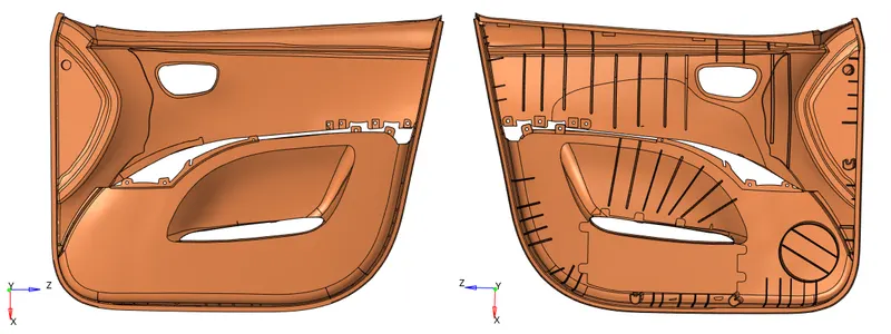
This is a plastic component with varying thickness across the component. The preprocessing process for such component is as follows:
- Analyze the geometry and perform the cleanup
- Extract the midsurfaces and cleanup the geometry
- Organize the midsurfaces into different components according to the thickness
- Generate 2D mesh for extracted midsurfaces
- Check for errors and quality criteria
- Assign thickness to the mesh
This is a 3D scanned model of the side door panel. So, there are a lot of geometrical errors in the model. For eg, the image below shows the missing surface which can be viewed by switching the view to By Topo. The free edges (red) shows where the surface is missing.
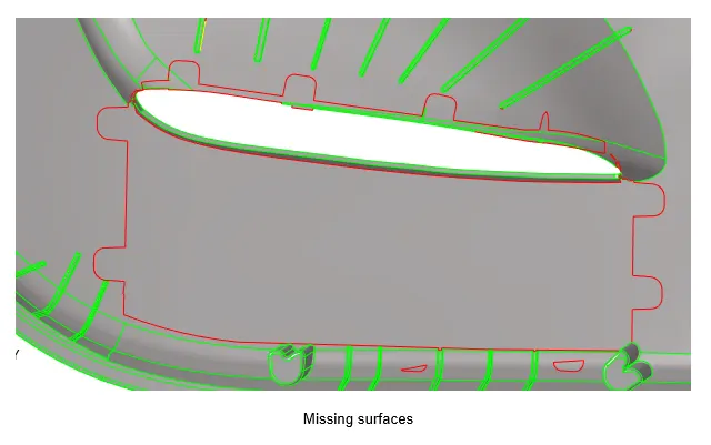
A large portion of the surface is missing. And the model has a complex geometry, so it won't be an easy task to reconstruct the missing surfaces accurately and would take a long time. And, the model being of complex geometry, the auto midsurface extraction might not even work properly. Also, the opposite surface is perfectly fine with no errors. So, it is better to extract the midsurface manually using the surfaces on opposite side.
As the component is of varying thickness, midsurface extraction for different regions needs to be performed separately according to the thickness. Therefore, first, we need to measure the thickness of the component in different regions. The process to measure the thickness is as follows:
- Create a node on a surface of either side.
- Then duplicate and project the node on the opposite surface using normal to surface option with project tool in Tool panel
- Then switch to wireframe view and measure the distance between the two nodes using the distance tool in Geom panel
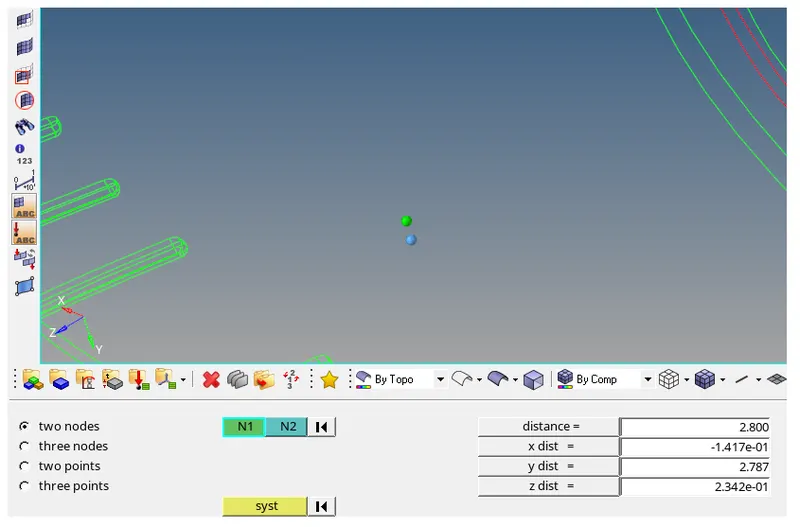
As shown in the image below, the thickness for this particular region is 2.8mm. Similarly, the thickness is measured for all regions.
After knowing the thickness, we can proceed to extract the midsurfaces. Manual midsurfacing is performed by offsetting the surface of either side by a value equal to half of the thickness, i.e., to the middle.
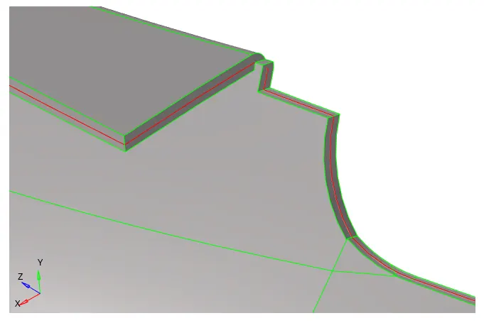
Before extracting the midsurface a new component is created to contain the midsurface and set as the current component. Now midsurface is extracted by using the Offset tool under Geom>surface edit>offset. Then, the surface to be offset is selected and duplicated and the offset value is given equal to half of the thickness in that region. The image below shows the extracted midsurface in the middle of the component.
Similarly, midurface is extracted for all the regions and kept in different components according to thickness.
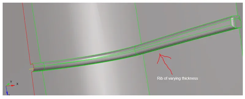
Next, we need to extract the midsurface for the ribs and join them to the base surface. And, there are few ribs where the thickness changed continuously along the length as shown below.
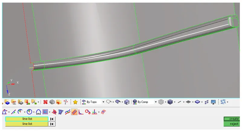
So, instead of defeaturing and offsetting, a different approach is used. First, a line is created in between the two opposite lines along the length of the rib on top using the Midline tool by going to Geom>lines>midline as shown below.
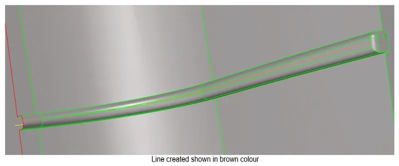
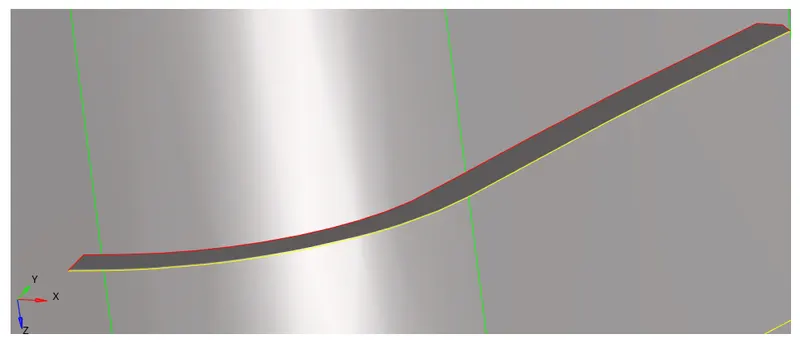
Similarly, another line is created using the bottom two edges of the rib. And then, the surface is created between these two created lines using the Ruled tool under Geom>surfaces>ruled. Then, the created surface is joined to the base surface by using the Extend tool under Geom>surface edit>extend, with extend over edges configuration.
The image below shows the extracted midsurface of a rib and joined to the base surface.
Similarly, midsurface is extracted for all the ribs, joined to the base surface, and kept in different components according to the thickness.
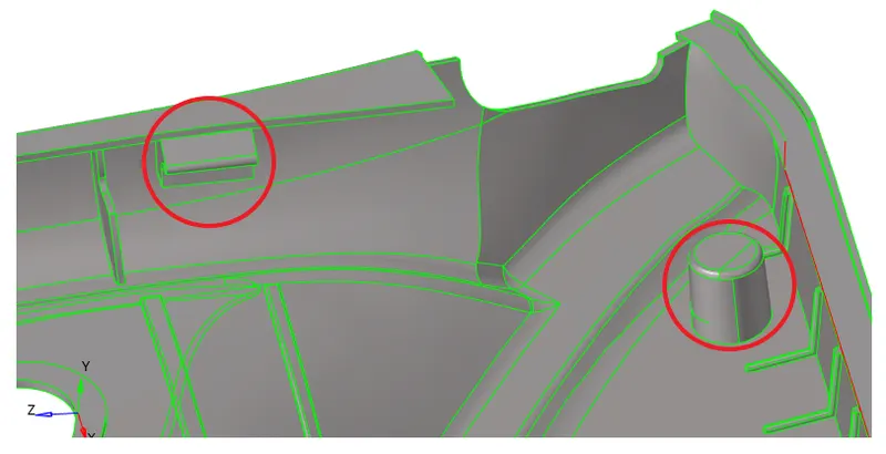
There were few parts that were thicker than 5mm and thus 2D shell meshing for them is not suitable and thus neglected, as shown in the image below, encircled in red.
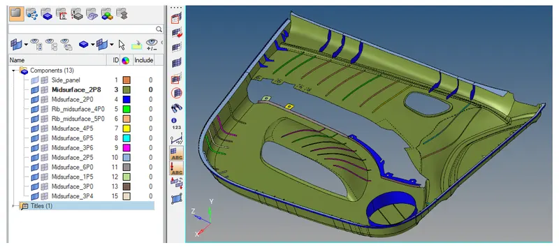
After extracting all the midsurfaces, geometry cleanup is done. There were few places where surfaces were intersecting and few places where surfaces were not joined properly. Such issues were fixed using the surface edit tools and quick edit tools like replace point, trim surface, etc. The image below shows all the midsurfaces extracted along with the component tree created according to the thickness. All the midsurfaces can be approximated within these components (thickness).
After geometry cleanup, 2D meshing is done. We are assuming that the mesh model will be used for crash analysis and thus rotational quads are not at all acceptable. In a few areas, trias are acceptable though they should be kept to a minimum number. Also, while dealing with the trias, it is ensured that there is no high concentration of trias in a region, no trias touching each other, and no opposite trias.
2D meshing is done using the automesh tool under the 2D>automesh tool panel with an element size of 4mm and mesh type configured to mixed. To refine the mesh, remeshing is done by selecting the elements to be refined. Rebuild mesh tool is also used to refine the mesh quickly.
Finally, after creating the mesh, elements are checked for quality criteria. To repair the failing elements several tools were used like remeshing those elements, element optimization, node optimization, element cleanup, etc.
After that, the mesh is checked for connectivity and duplicate errors using the find edges tool under Tool>edges. Elements with connectivity issues are connected using the replace node tool.
Finally, the property is created for each midsurface component by right click>create>property in the component tree panel. And the respective thickness is configured for each. Then the created property is assigned to the respective midsurface component. Average thickness is assigned to ribs that had varying thicknesses.
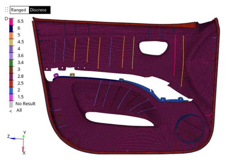
The final mesh generated is shown below with view set to By thickness.
Conclusion:
2D shell mesh was successfully generated for the plastic component with varying thickness. All the elements passed the quality check and tria concentration was kept low at 0.97% only. Mesh was checked for free edges and no connectivity issues were found.