Meshing of Side Door Inner Panel using HyperMesh
Project 1: Side Door Inner Plastic Panel
Aim:
The goal is to extract the mid surface, generate the mesh, and to add the thickness to the given side door inner panel using the Following Quality Criteria.
Target Element Length = 4mm
|
S. No. |
Quality Criteria |
Value |
|
1 |
Aspect Ratio |
5 |
|
2 |
Skewness |
45 |
|
3 |
Warping |
15 |
|
4 |
Taper |
0.5 |
|
5 |
Min. Length |
2mm |
|
6 |
Max. Length |
6mm |
|
7 |
Min angle Quad |
45 |
|
8 |
Max angle Quad |
135 |
|
9 |
Min angle Tria |
20 |
|
10 |
Max angle Tria |
120 |
|
10 |
Tria % |
10 |
Methodology:
The methodology for the given model is as follows.
- Opening the File.
- Extracting the Mid Surface.
- Giving the Quality Criteria.
- Generating the Mesh.
- Clearing the Errors.
- Applying Property.
- Giving the Thickness.
Theory:
Side Door Inner Panel:
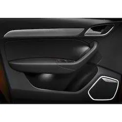
A structural inner-door panel for a door of a vehicle, such as a truck, has a body that is monolithic and molded as a single piece of polymeric material. The body has a front side which faces towards the inside of the vehicle, and a backside opposite the front side. The body substantially spans the width of a truck door frame and substantially spans the distance from the bottom of the door frame to the window opening. The body panel serves as a portion of the interior decor of the door without the need for additional structural support members other than the exterior metal panel of the door. The body front side is configured to have trim pieces and accessories attached thereto. The body may include an integral armrest, storage compartment, and a radio speaker well. The backside has a plurality of baffles projecting outwardly therefrom to provide strength and rigidity to the panel.
Door panels serve as an interface between the interior of the car and the inner workings of the door, and between vehicle occupants and the door. They are expected to meet a variety of design specifications regarding safety, aesthetics, and functionality. Also, they are expected to continue the material theme of the dashboard and pillars while concealing intricate electrical and mechanical components for operating locks, windows, and other features. The door panel has evolved from a simple two-part system of latch and simple winding mechanism to a more sophisticated enclosure. Doors currently have an inner full-width panel consisting of electronic windows, a central locking system, and speakers. These panels typically consist of a foamed core covered with either textiles or plastics.
Procedure:
- Opening the File:
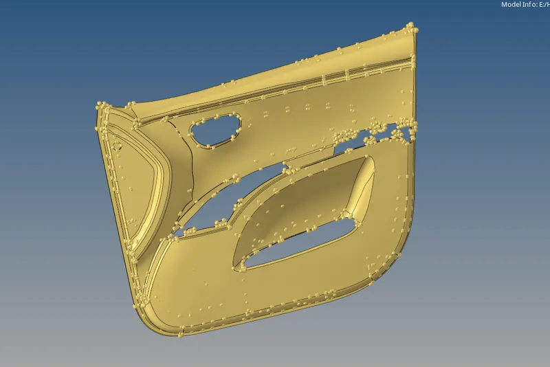
- The File given is a ‘.hm’ File. It can be opened directly by following the steps.
- In the Main Bar, Select File >> Click Open >> Click Model>> Select the File to open >> Click Open.
- The file is opened. To view the Model (if the Screen is empty), Click ‘f’ on the keyboard to fit the model on the screen.
- Extracting the Mid Surface:
- The Model consists of different thicknesses and it is a plastic component and therefore the auto mid surface option doesn’t work.
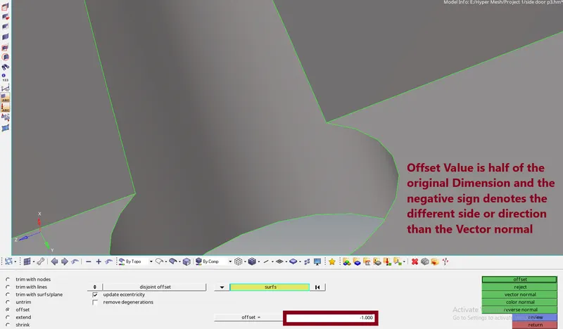
- We use Offset for extracting the mid surface for the varying thickness components in the same model. The steps to achieve the mid surface are directed below.
- In the Geom Tab, Select Surface Edit >> Check the Offset option >> Select the Surface to create the mid surface >> click on surfs >> Click Duplicates >> Select current comp >> Give the Offset value >> Check for the Direction of the offset by clicking the vector normal >> If the direction is opposite to the mid surface generation, Click reverse normal or prefix the offset value to ‘-’.

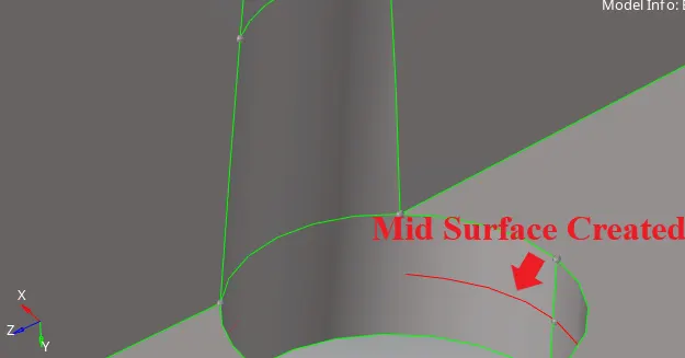
- For Rib Parts, since the ribs consist of varying thickness, therefore, the offset is not possible. TO create a mid surface, a mid-line needs to be created.
- To create a mid-line, Go to the lines panel in the Geom Tab >> Click Midline Option >> Select the 1st Line >> Select the 2nd Line >> Click Create.

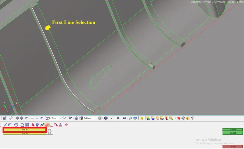
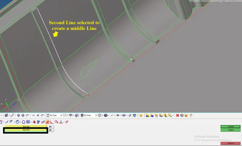
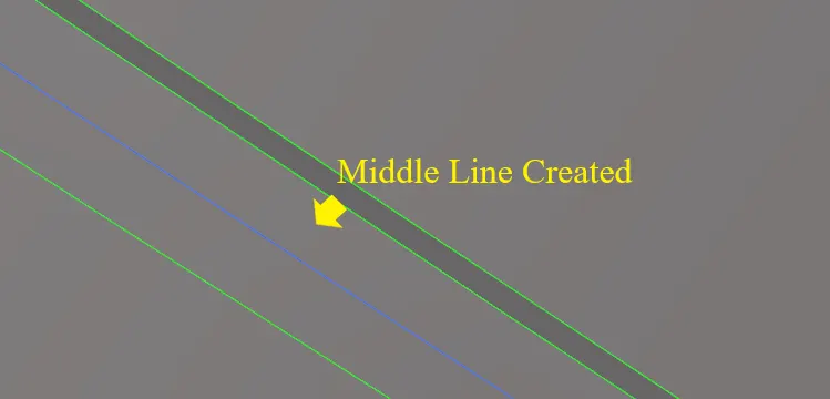
- The Middle Line is created. Now the Line needs to be projected to the Mid surface of the component where the rib is getting attached in the parent geometry.
- To Project, Click Shift+F7, or Go to the Project panel in the Tool Tab >> Select to surface option >> Change the option from Nodes to Lines >>Select the surface to extend >> Click Project.

- The Line is projected. Now the Surface is needed to be created.
- To create the surface, Go to the Surfaces option in the Geom Tab >> Select Ruled Option >> Select the 2 Lines to create the Surface>> Click Create.

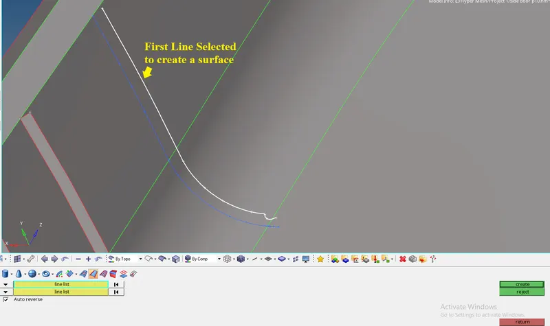
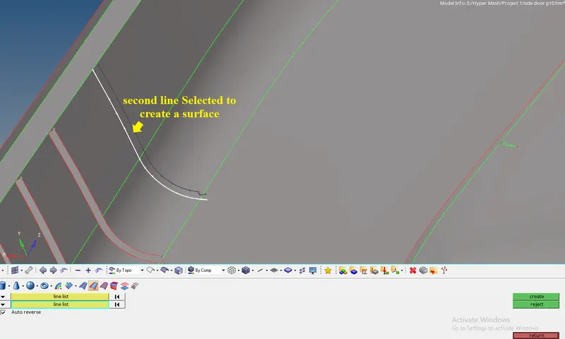
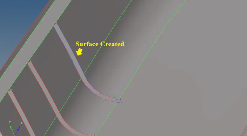
- The Mid surface is created for the Rib parts.
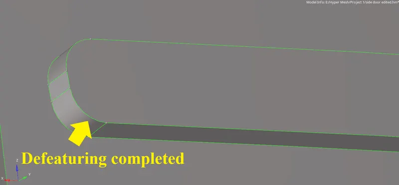
- For some of the Ribs the thickness is same but the curved fillet is formed. To make the curved fillet region to normal surface, we can make small adjustments to the rib by defeaturing.
- To defeature, Go to the Defeature panel in the Geom Tab >> Select the surface fillet option >> In find Fillets in select option, select the surface where you want the fillet to be defeatured (Note: Best to select the total area nearby to get rid of any irregularities.) >> Give the Min radius as less than the given quality criteria minimum length. >> Click Find >> The Surface gets selected where it is failing for Minimum Length >> Click Remove.



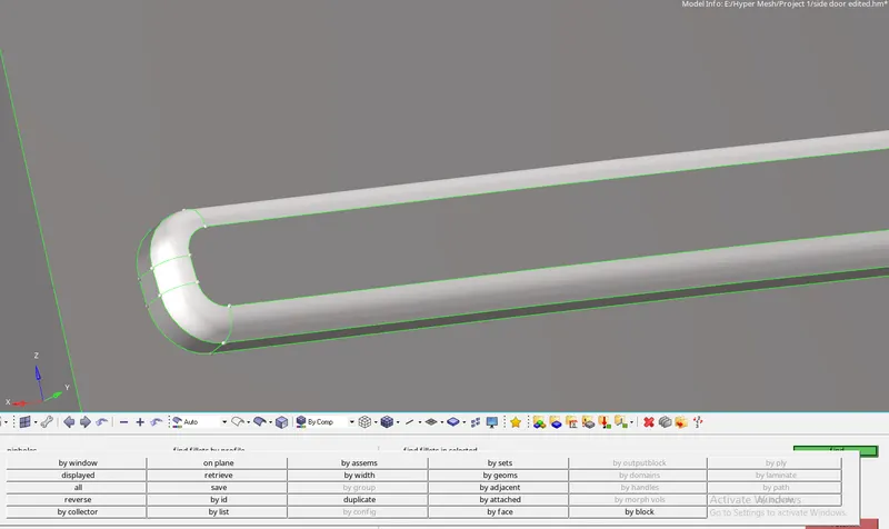

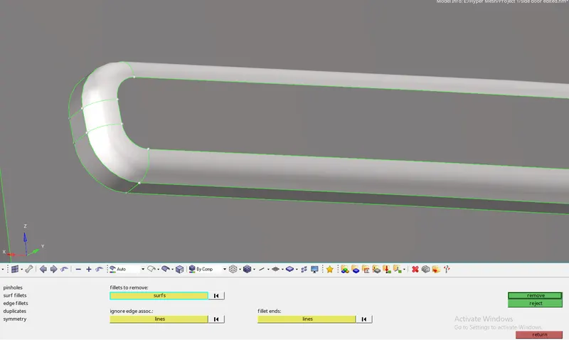
- Giving the Quality Criteria:
- The Quality Criteria is an important task which is to be used to get the required outcome of the mesh.
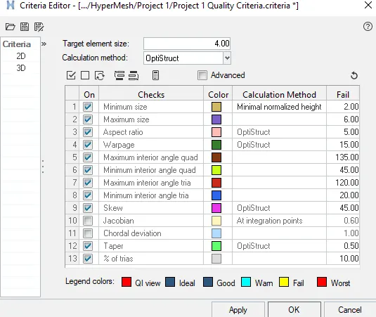
- This helps to retrieve the mesh with the given criteria. To give the criteria,
- Go to the Preferences tab in the Main Menu >> Click Criteria file settings >> Give the values as given >> Click Apply. >> Click Ok.
- The Quality Criteria are given.
- Generating the Mesh:
- To mesh the model, either the whole model is selected at a time or a part of the model is selected separately.
- Go to the 2D window, Click auto mesh >> Select the surface to mesh >> Give the Element size >> Keep the mesh type as mixed >> Click mesh.

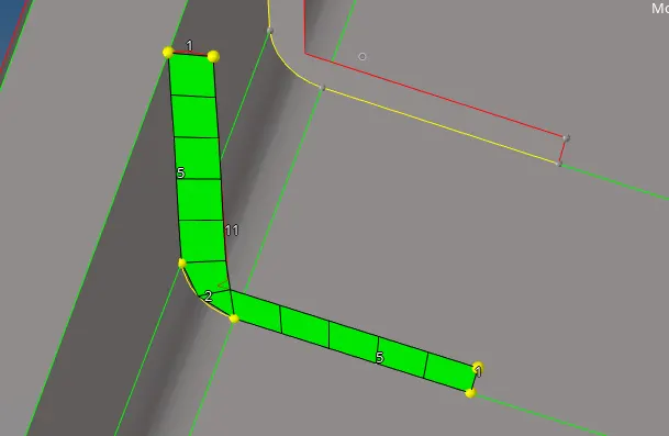
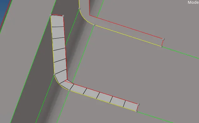
- The mesh is created.
- If the mesh flow is not good, select the down arrow beside surfs to change it to elements >> select the elements to re-mesh >> click mesh the software gives the optimal mesh.
- Clearing the Errors:
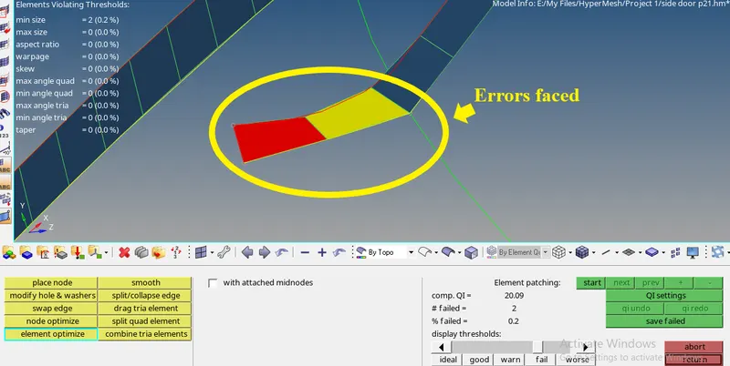
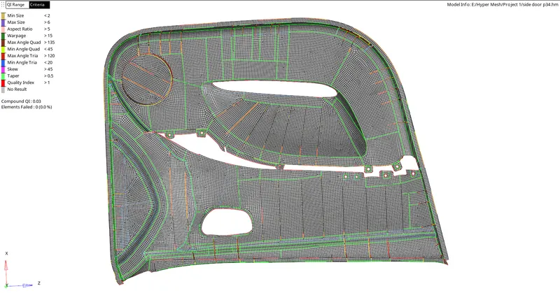
- The errors occur when the elements fail to meet the given quality criteria.
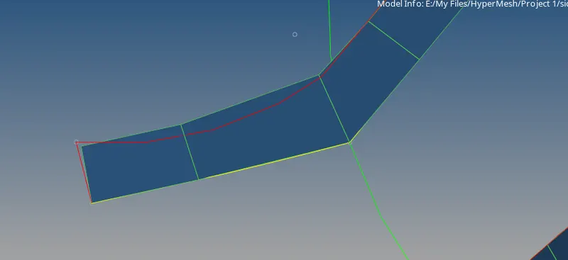
- To clear the quality criteria, Go to the 2D panel, Select quality Index >> Click cleanup tools >> Select the tools you want to use to clear the Errors.
- The errors will be cleared.

- Applying Property and thickness to the Component:
- Property is given to the components so that the thickness of any other properties can be added to the part.
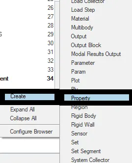
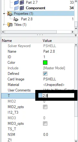
- To create a property, Right-click on the space in the Tab bar >> select Create >> Select Property >> Give a name to the Property Created >> Give the Thickness as per the parent geometry.
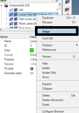
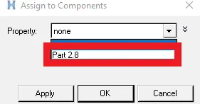
- To assign the property to the component, Go to the components tab >> select the component in the tab bar >> right click on the component >> click assign >> A new Dialog box appears >> Select the property to assign >> Click Apply and then Click Ok.
Terms Used:
- De-featuring:
De-featuring is the removal of details in the geometry to make the shape of the part simpler. It makes the model easy to extract the mid surface or to perform the mesh without the elements failing for min length. It can be done only if the changes made don’t affect the model drastically.
- Offset:
Offset is a method used to create a surface or a component that is needed at a particular distance. In engineering, the offset is an adjustment of tool positions in machines to compensate for their wear, finishing, or displacement from an axis.
- Aspect Ratio:
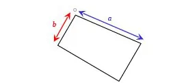
Aspect Ratio is the ratio of the width to the height of the FE part.
- Skewness:
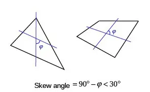
- Skewness refers to distortion or asymmetry in a symmetrical bell curve, or normal distribution, in a set of data.
- If the curve is shifted to the left or the right, it is said to be skewed.
- Skewness can be quantified as a representation of the extent to which a given distribution varies from a normal distribution.
- Warping:
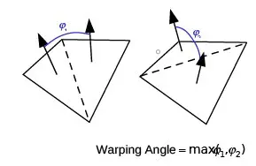
- Ideally, all the nodes of the quadrilateral element should lie on the same plane but at curvatures and complicated geometry profiles, it is not possible. Generally, the measure of planeness of a Quadrilateral is called Warping Factor or Warping Angle.
- It is defined as the angle between the normal of two (triangular) planes formed by splitting the quad element along diagonals.
- Maximum Angle out of the two possibilities is reported as "Warp Angle".
- In the case of solid elements, an element's face deviates from being planar. The quad is divided into two trias along its diagonal, and the angle between the trias normals is measured.
- Ideal Value = 0° ( Acceptable < 5° to 10°)
- Taper:
- Taper occurs when the angular distortion of a quadrilateral shell element approaches 180. When you check your mesh, Hypermesh uses the Taper quality measures to highlight elements having angles between included edges that exceed the minimum taper angle.
Tools Used:
- Offset:
- The Offset tool in the Hypermesh creates a new surface of the selected original component at a given offset value (i.e. at a particular distance away from the parent geometry).
- To explain clearly, Use the Offset subpanel to offset a group of surfaces by a given distance along the normals of those surfaces. A negative offset value can be used to offset these surfaces in the opposite direction of the surface normal.
- The topology of the surface edges (free, shared edges, and so on) is maintained during the offset function. Some individual surfaces will be trimmed or extended to maintain the connectivity. This function moves the selected surfaces to the new location.
- If you want to save the original surfaces, the selected surfaces can be duplicated before the offset. You can review the normal direction of the surfaces by clicking the vector normal or color normal.
- If the offset direction is incorrect, the reverse normal function can be used to reverse the normal of a selected surface.
- If there are elements associated with the offset surfaces, the element will not move along with surfaces. The association between the elements and their surfaces is broken.
- There are two major types of offset: disjointed and continuous.

- Extend:
- The Extend tool as the name suggests it extends the surface to the selected opposite surface. It is used for the perpendicular surfaces.
- Use the Extend subpanel to extend or retract the edges of selected surfaces to meet other selected surfaces, or to close gaps between surfaces or holes within a selected surface.
- Several options affect how surface extension behaves, including enabling or disabling the ability to shorten edges as well as extend them, or to force the extended edges to attempt to maintain the overall shape of the surface.

- Place node:
- Place nodes option is used to move the nodes from a particular point to the required point.
- The Place node is a useful yet destructive tool which if used can optimize the mesh flow or move the nodes away from the flow of the elements or by distorting the elements.
- The place nodes should be used only while doing 2D meshing.
- Smooth:
- Use the Smooth cleanup tool to improve element quality in a surface-based mesh.
- This cleanup tool uses one or more algorithms to adjust node positions to moderate sharp variations in size or quality in adjacent elements and to adjust the position of the free nodes of the selected shell elements to smooth out variations in element quality and size.
- Split/Collapse edge:
- Use the split/collapse edge cleanup tool to split or collapse the edges of elements in your model.
- To use the split edge tool, left-click on an edge. HyperMesh splits the elements that share the selected edge in a way that will achieve the optimum quality.
- Swap Edge:
- Use the Swap Edge tool to consider the elements to which the edge belongs, and find alternative orientations for it.
- Each time you click an edge, it switches to the next valid configuration. If an edge swap will not improve element quality, a message to that effect displays in the status bar. To force the swap anyways, click the edge a second time. Additional clicks will cycle through the possible edge positions. The number of possible edge positions depends on the types of elements involved.
- For a pair of trias, there are two possible positions for their shared edge. For a pair of quads, there are three possible positions. For a quad and a tria, there are six possible positions.
- Drag Tria element:
- Use the drag tria element cleanup tool to drag a tria element to a different location in the model, or out of the model completely.
- To use the drag tria element cleanup tool, left-click on a tria element and drag it to a desired location. HyperMesh highlights the selected tria element in pink.
- Split quad Element:
- Use the split quad element cleanup tool to split a quad element into two tria elements.
- To split a quad element, left-click on the quad element you wish to split. HyperMesh splits the quad element into two tria elements.
- Combine Tria Elements:
- Use the combined tria elements cleanup tool to combine two tria elements into one quad element.
- To combine two tria elements, left-click on their shared edge. HyperMesh combines the two tria elements into one quad element.
- Element Optimize:
- Use the Element Optimize tool to automatically optimize the shape of the selected element and the elements surrounding it. It is similar to Node Optimize, except that its effects are wider-spread.
- To move the mid nodes attached to the element you are optimizing, enabled the with attached mid nodes
Result:
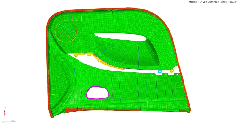
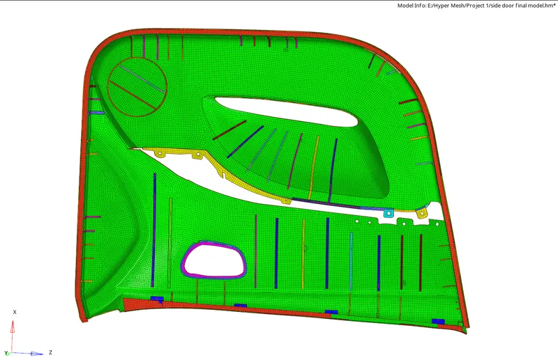
The mid surface, mesh, and thickness are assigned for the given side door inner panel model.
Final Model:
Final Model Without Errors:
Final Thickened Model:
Learning Outcome:
Each challenge teaches us something new. In this project, the learning outcomes are as follows.
- Learned to use the Offset tool efficiently.
- Learned to use the replace option to make minor changes to get the proper mesh flow.
- Learned to use De-feature tool to achieve simpler features.
Links:
Google helped to learn most of the techniques, tips and about the tools used and how they are used. Here are some of the links used to get the knowledge.
https://www.sciencedirect.com/topics/engineering/door-panel
Regarding the knowledge gained of the Tools used is from opening the Tool option and Clicking F1.