Week 12 - Project-1_-side door inner panel
Aim :
To perform the 2D shell meshing on side door panel
Objective :
Perform the geometrical clean up on the side door model followed by shell meshing using the stated quality criteria. After meshing the component, the thickness has to be assigned.
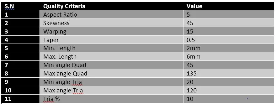
Target element length : 4
Introduction :
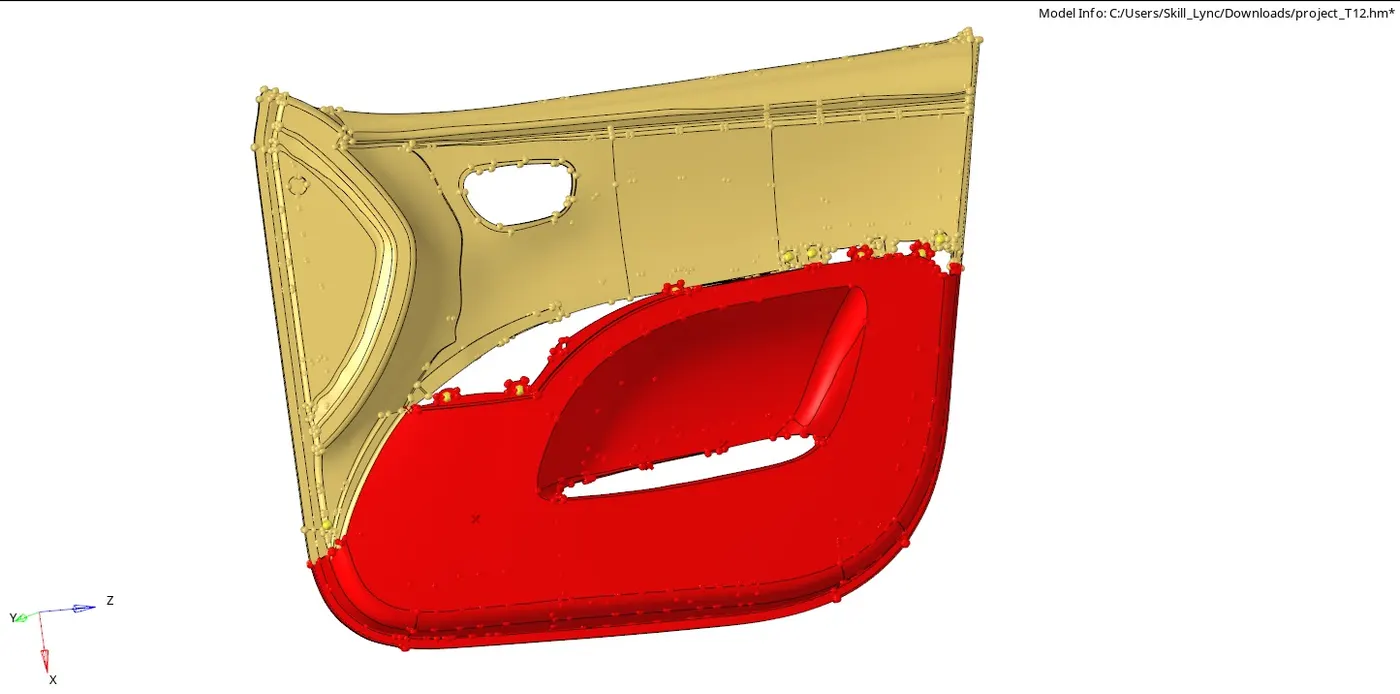
The model for 2D meshing provided is the side door of a passenger car that needs to be pre processed in the hyperworks. Side door is the component which is provided here is the plastic part of the side door that fits inside the passenger cabin. It has some a compartment for keeping the essentials or bootle and to the other regions are the ribs and docks that provide stiffness and help in fitting this part to the actual side door aluminium part .
Procedure :
Step1 : Importing the model into Hyperworks.
The Side door file is imported to hyperworks workspace (file extension is .hm)
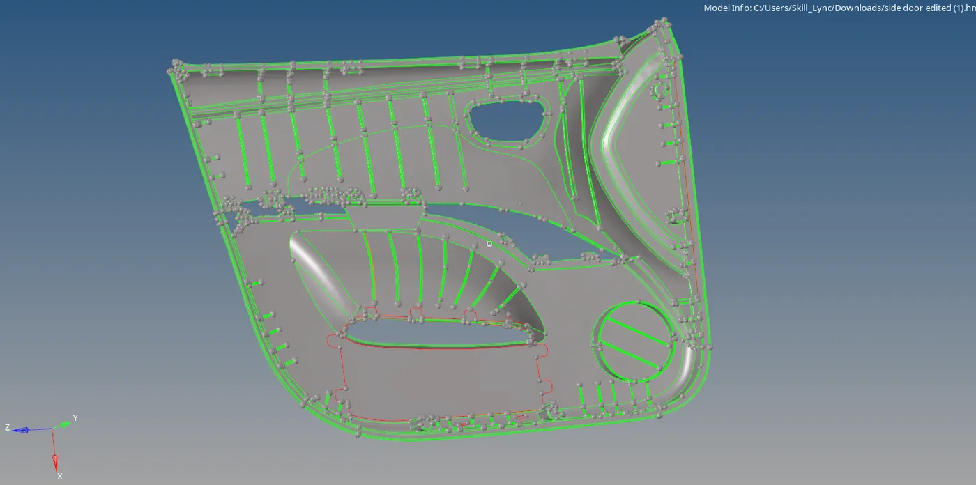
Fig - side door panel imported to Hyperworks
Step 2: Defeaturing / cleaning up the geometry.
The side door model is actually a bit complicated as it has small ribs and features. Here we are going to organize or separate the component into two. This is done because while extracting the mid surface the distortion is likely to happen which may damage the rest of the surface.
Tools >organize>surfs

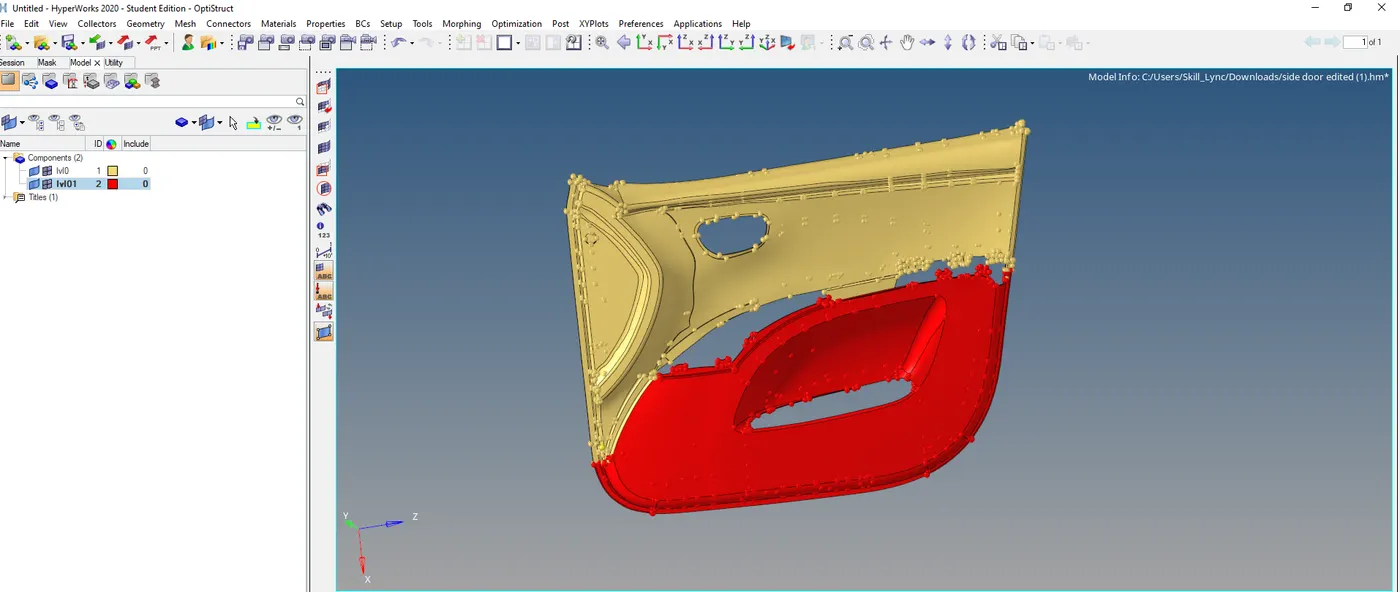
Fig- Side ddor organized into 2 parts.
Geometry clean up means cleaning or preparing the geometry for the mid surface and meshing operation. Before extracting the mid surface the geometry has to be checked and cleaned from following errors.
- Free edges
- Scar lines
- Duplicate surfaces
- Small fillets
- Small holes
- Beads
Defeaturing :
Also one important part of clean up is the defeaturing the small fillets that are difficult to capture in the midsurface. To do that
Geometry >defeature > surf fillets > select the fillets surfaces

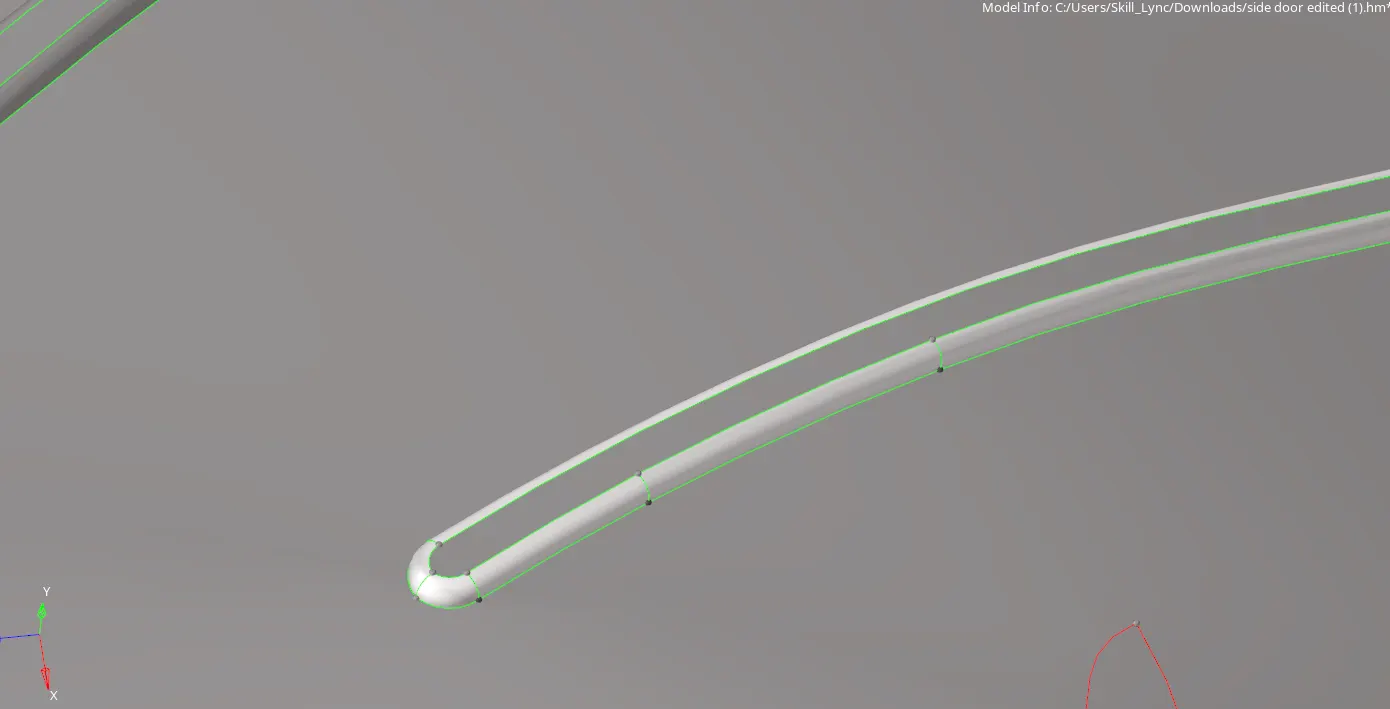
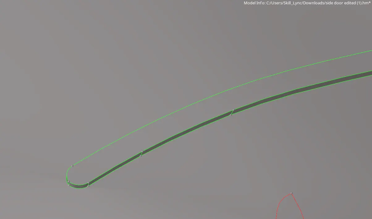
Fig- Fillets defeaturing
The minimum and the maximum values for the fillets need to be fed that will be defeated( here 0.1 and 3 respectively ). The fillets are defeatured to form sharp edges that are easier to capture in mid surface.
Also the two lines which are quite near to each other need to be removed or replaced to form a single line. This can be done by using the replace point option.
Geometry > quick edit tools or F11 > replace points .

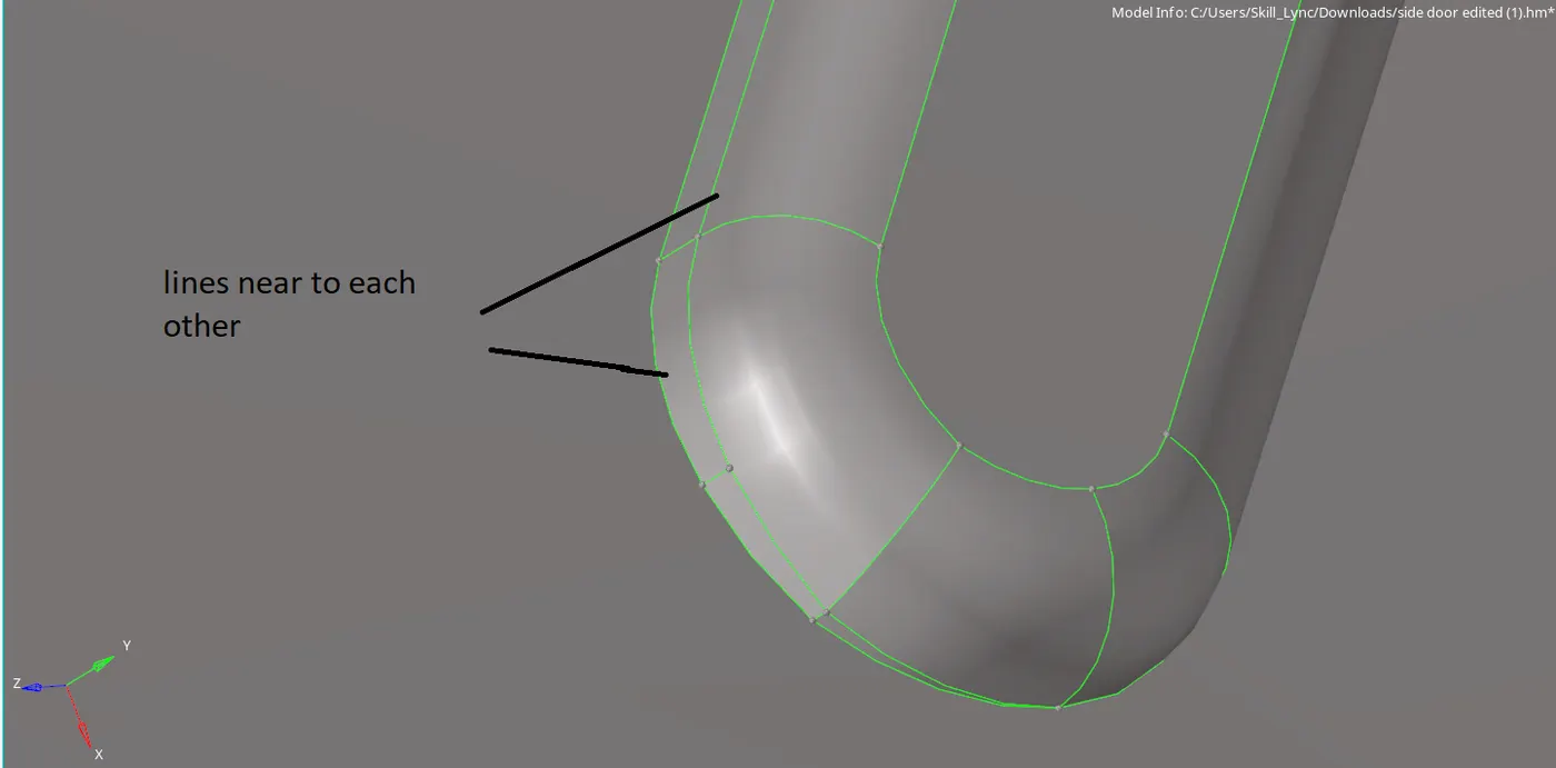
IFig- 2 lines near to each other
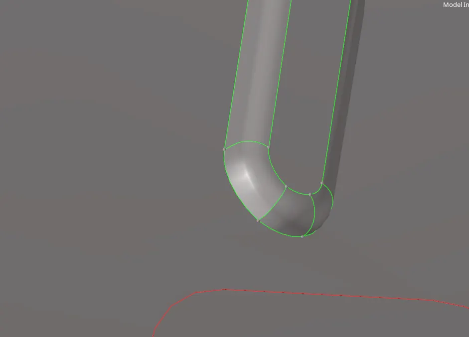
Fig - lines combined with replace points.
Step 3 : Creating the mid surface
Before extracting the mid surface the model has to be reviewed or analyzed and measurement has to be carried to find the thickness of the geometry or features.
Tools > distance or F4 > two points

Now the mid surface can be extracted by various methods two methods
- Offset / manual
- Auto mid surface
Auto mid surface extraction method is used in the conditions where the geometry is having the uniform thickness with less features or ribs. But here the geometry is not having a proper or uniform thickness.
Moreover the ribs are also having the varying thickness and cross section. So the final approach to extract the mid surface for the given side door is the manual or offset method.
Geometry > surface edit > offset

The surface selected has to be duplicated first and checked for the normal vector direction .
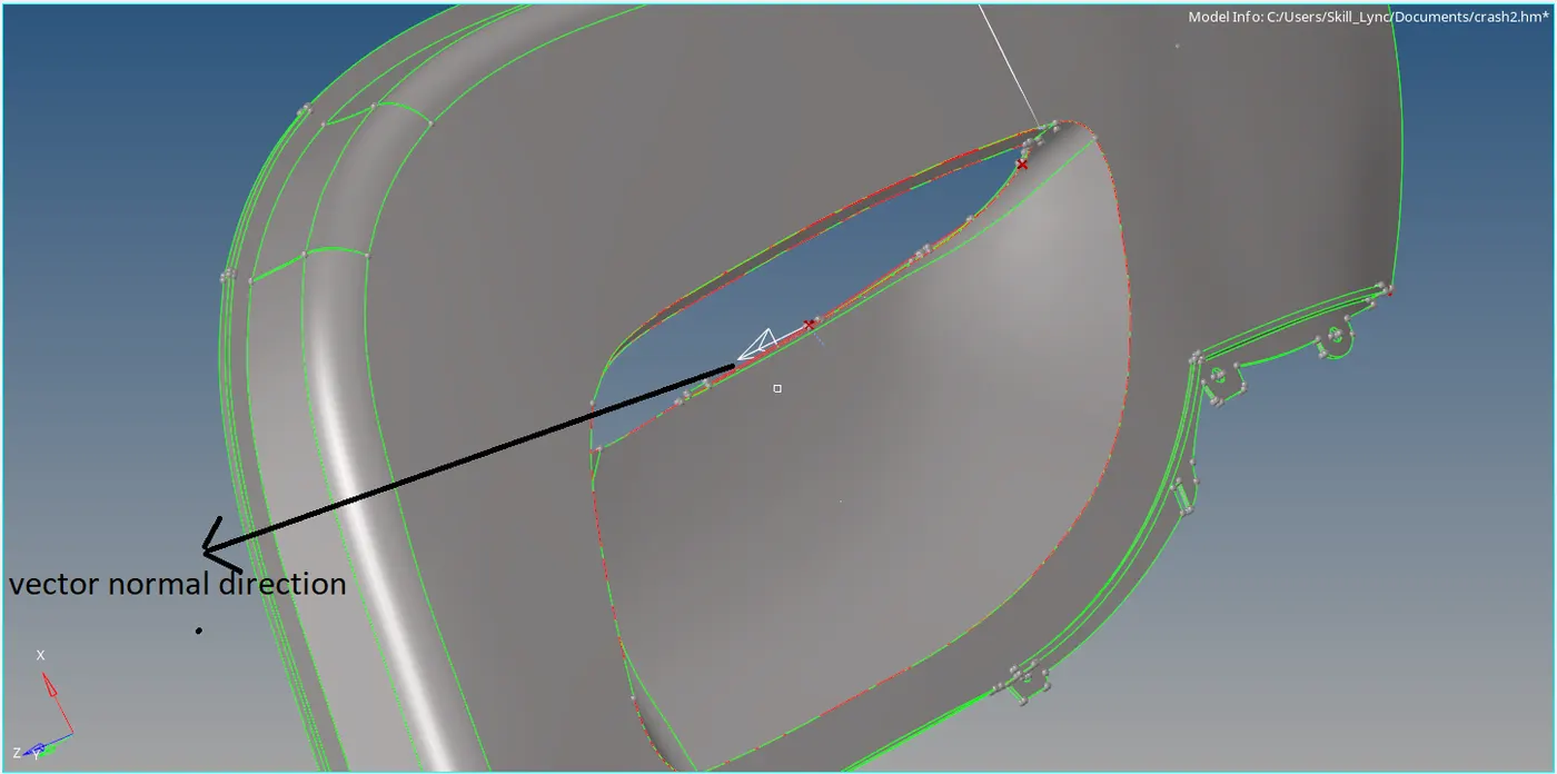
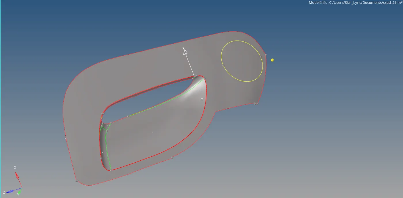
Fig- Mid surface after offset
Since the final mesh has to be assigned with thickness , so everytime the mid surface is created with a separate component id named with its thickness.
This was done in an earlier stage so that at the end we don't have to measure the thickness for each region again.
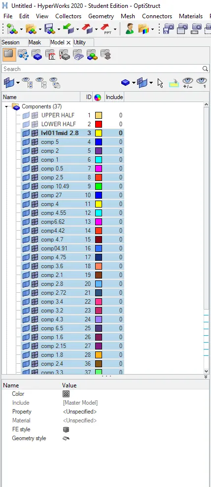
Fig - Creating components with their thickness name
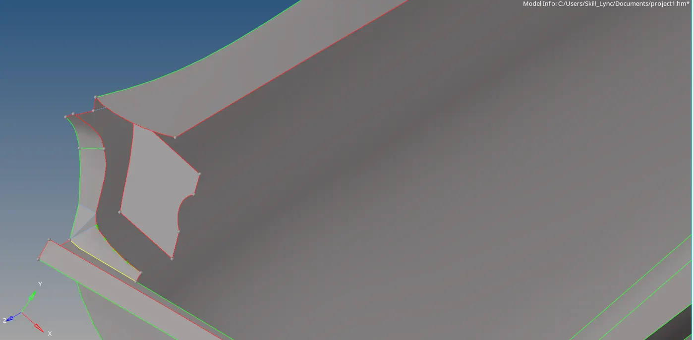
Lines for mid surface :
Some of the ribs here are having varying thickness while some others were not defeatured properly. Then while offsetting the mid surface won't be at the middle or exact location.
To overcome this problem lines and surface options are used to create the mid surface.
- Create the mid line using line option Geometry>lines > midline

- Project this mid line normal to the base mid surface .
Tools >project >to surface> line > normal to surface
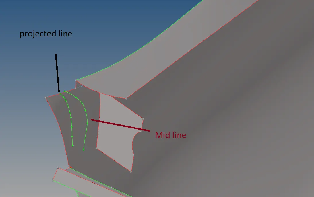
- Then create the new surface from this to lines
Geometry >Surface >ruled
Trim :
Some of the surface obtained may get intersected but are not joined geometrically. This surface needs to joined using the trim option
Geometry > trim > trim with surf
The rest of the protruding surface can be deleted to obtain the required mid surface.
Extend :
All the mid surface that is extracted manually region by region needs to be joined together. To do that we use the extend surface.
Also the extend option is sometimes used in the ribs where it is required to obtain the true height .
Geometry> surface edit > extend

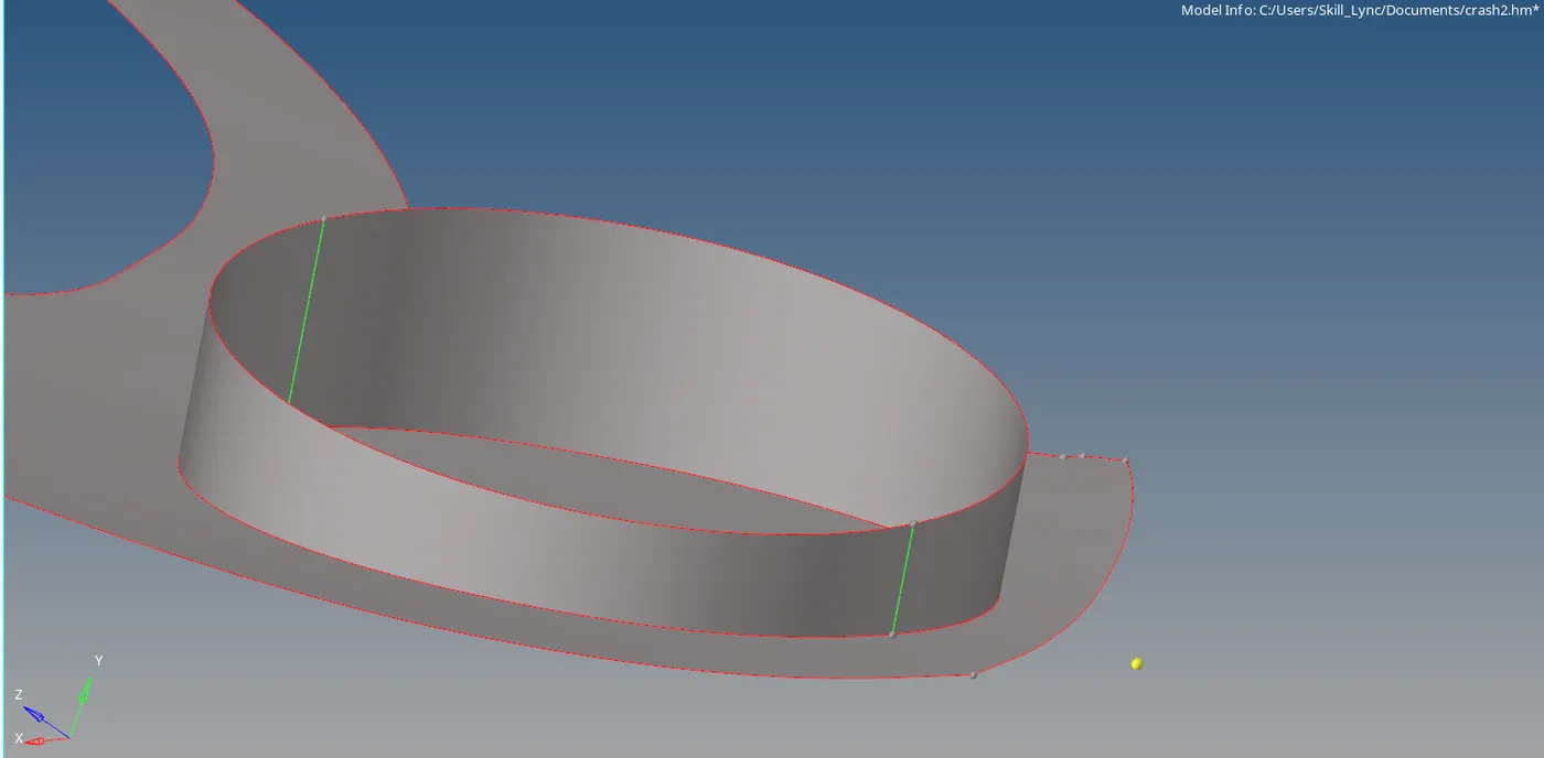
Fig- Cylinder needs to be extended to base
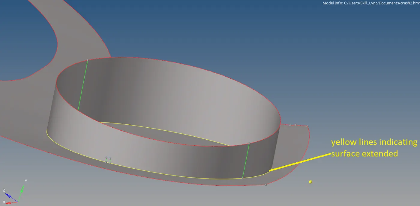
Fig - Cylinder extended to base surface
The extended surface then edges are turned to yellow lines if there is a T joint or green lines if the free edges form a L joint.
Note :
The model has some docks pins that are used for fitting the component to the parent side door. Since they are the somewhat complicated or solid shapes, they have not been
captured in mid surface because they are made for solid meshing.
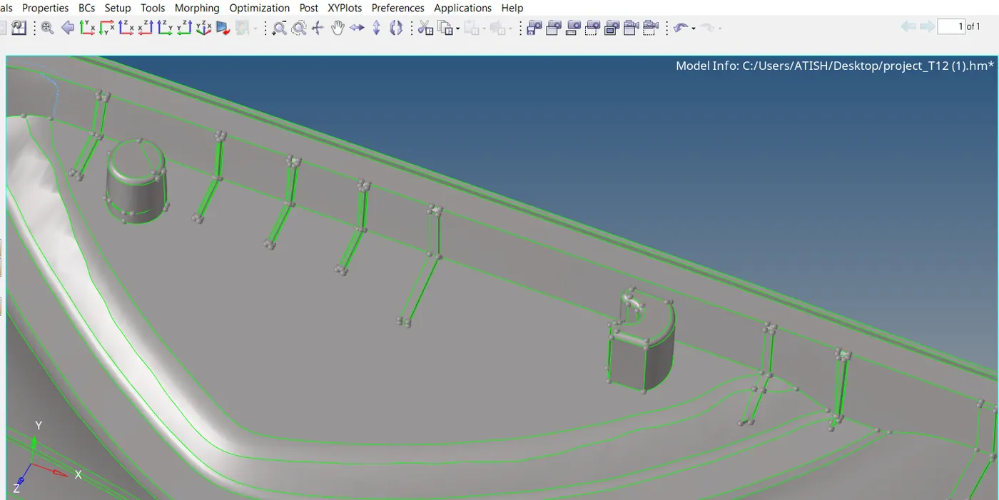
fig - dock pins not included for mid surface
Also there are also some regions which have been neglected in the mid surface because their alignment with the rest of the component is difficult and they are mostly a part of the mountings.
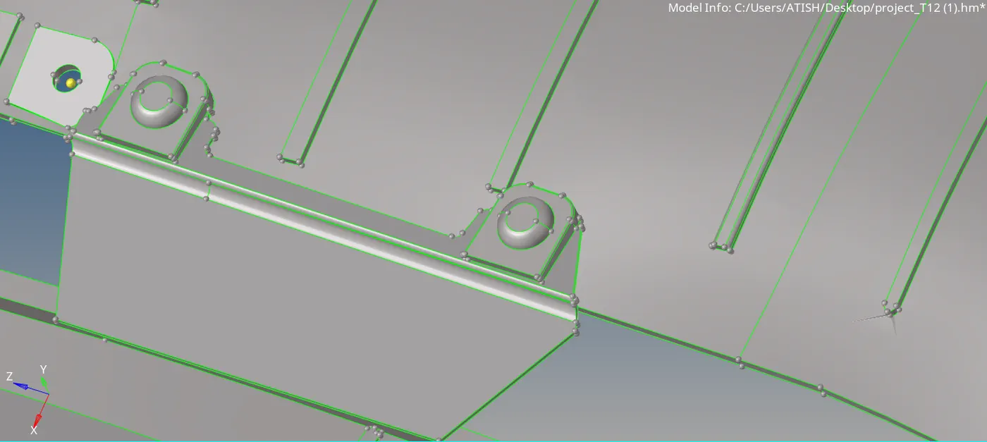
Fig - mounting plate not included in mid surface
Some other tools used to create the mid surface are translate , toggle , filler surface , projects
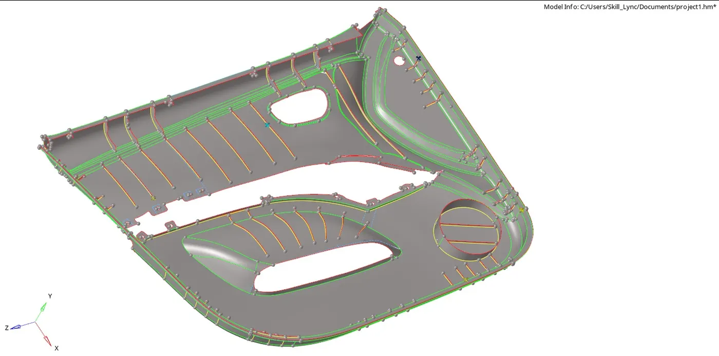
Fig - Final mid surface for the side door panel
Step 4 : Assigning the quality criteria and topology cleanup for mid surface
The topology clean up for the mid surface includes drawing and removing some construction lines in the regions to avoid the tria elements formations or to get the proper mesh flow.
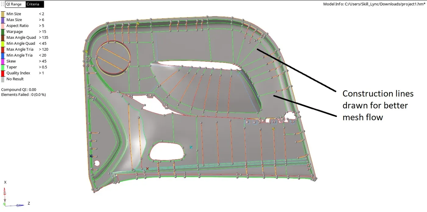
Fig- Topology clean up for mid surface
The quality criteria are followed before performing the mesh according to the requirement.
- Minimum and maximum length
Minimum as 2
Maximum as 6
This is to define the distance between two nodes over the surfaces. Any two nodes having distance less than 2 and greater that 6 will fail in element size
- Target length as 4 .
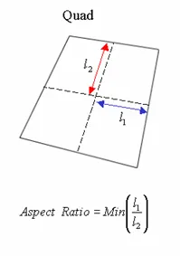
- Aspect Ratio:
The aspect ratio of a 2D element is defined as the ratio of its shortest edge length to its longest edge length. A square has the aspect ratio of 1 since its sides have the same length.
As it gets away from the square shape, the aspect ratio becomes smaller than 1.
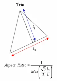
- Skew Angle
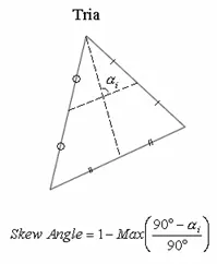
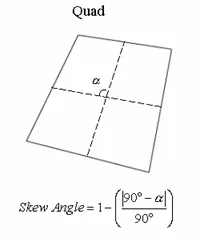
An angle is formed by the two lines which pass through the midpoints of the sides of the quadrilateral. The skew angle represents the absolute value of the difference between the angle and 90 degree.
A rectangle has the skew angle of 0 since the formed angle between lines is 90 degree. For the triangle and quadrilateral elements, the skew angle is found as shown in the figure.
For solid elements (Tetra, Hexa, Wedge), it calculates the skew angle for each element faces and assigns with the minimum value.
- Warpage
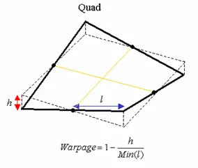
The warpage of the quadrilateral elements is defined as the deviation from a best-fit plane that contains the element. It is not always a case to define a plane with 4 nodes.
Therefore, a node of the quadrilateral element may be formed outside of a plane. The warpage is a measurement of how this node has been deviated, and
as it gets closer to 0, the element becomes more planar. For the quadrilateral elements, the warpage is found as shown in the figure. For solid elements (Hexa, Wedge), it calculates
the warpage for each element faces and assigns with the maximum value.
All the values for the quality criteria have to be fed before starting the meshing. To do that go
Menu bar >preferences > criteria file settings
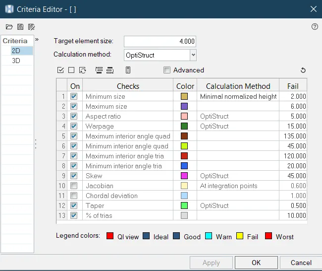
Fig- Inserting the quality criteria values
Step 5 : Performing the 2D meshing
Perform the meshing keeping in mind that no rotating quads and no opposite tria element Rectifying the errors of mesh. For convenience we switch on the view mode to by
element quality that shows the number of elements failing the criteria.
The meshing is approached by doing manually region wise using the construction lines that were created to help in getting the proper mesh flow with less tria concentration .
Rotate :
Rotate option is used to align or to parallel the edge of the elements to nearest the edges so that we can have quad elements in those parts.
- Go to distance > add one node in between in two nodes. This mode will be the base node for rotation of the elements .
- Then go to rotate > select the nodes of elements > select the N1,N2,N3 and then select centre node as the base node .

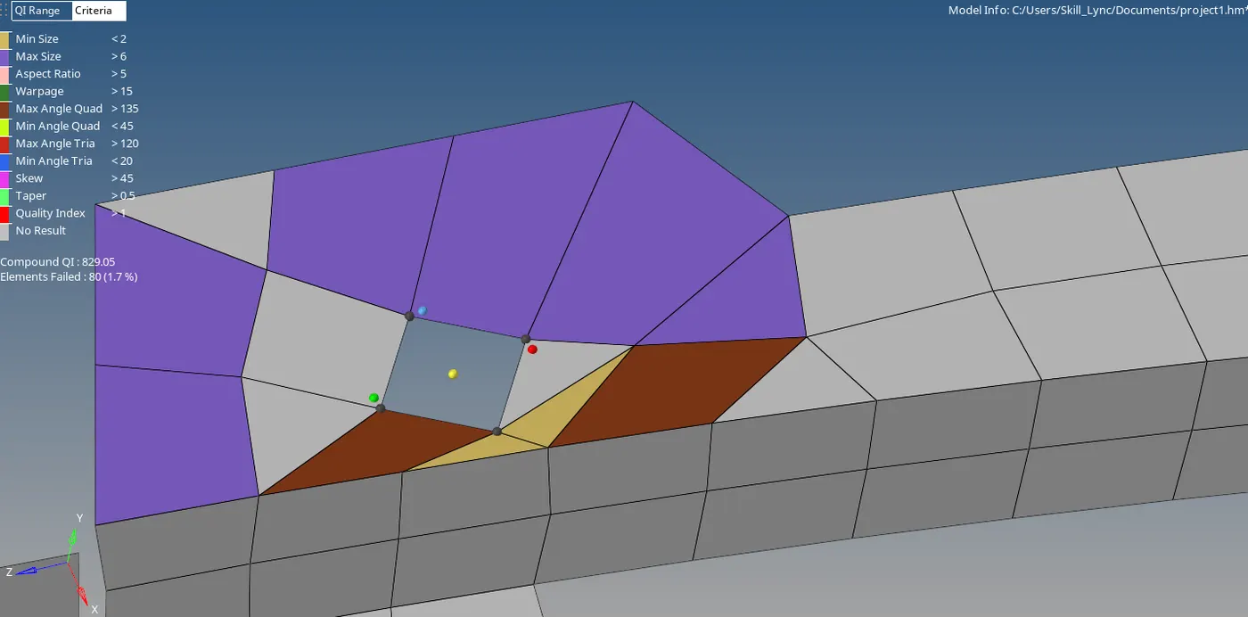
Fig- hole edge not parallel to adjacent edge.
- Insert the angle of rotation and rotate until the edge is parallel to the adjacent edge .
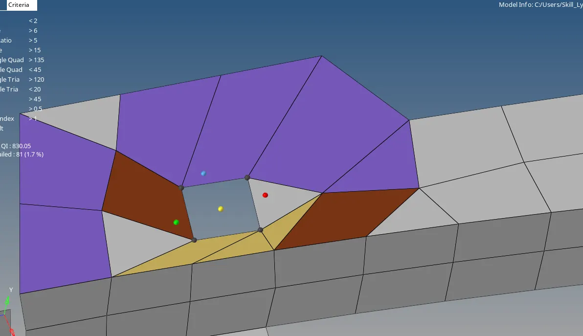
Fig- Hole edge parallel to adjacent edge
Rectifying the errors :
Warpage errors: these errors are shown in green color here and occur in quad elements. To remove these errors we use the translate option to orient the element properly.
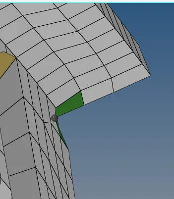
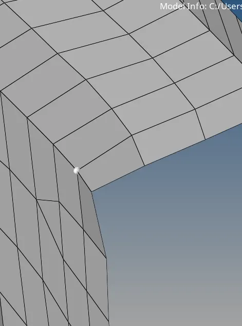
Fig - warpage error fixed using Translate option
Min and max length error : these errors arise when the element does set into a defined value .To rectify these use the distance option to change the distance or length of the elements.
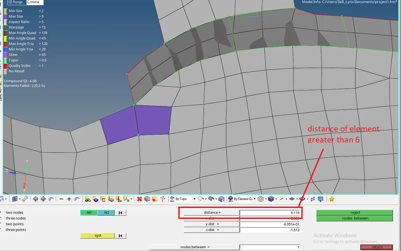
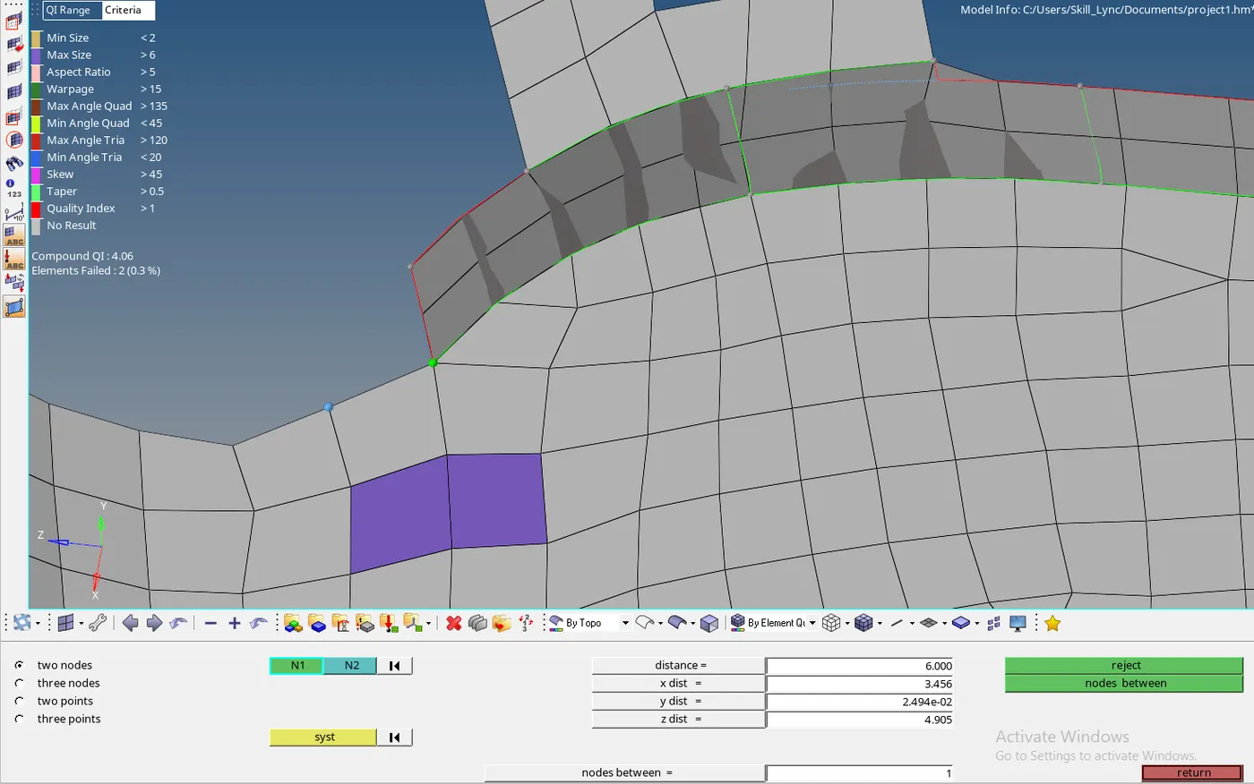
Fig- distance set to 6 to fix max length error .
Rotating quads : to rectify the rotating quads use the split option , split the quad into trai .
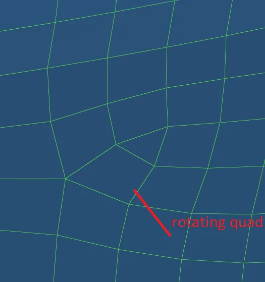
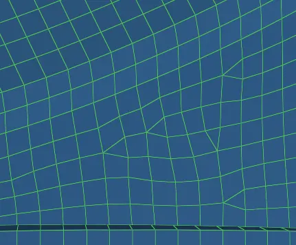
Fig- rotating quad splitted to form tria and dragged
Opposite tria : these can be eliminated by using the drag option and to join them as one present near each other also with proper mesh flow.
Using all the above tools the meshing is performed with proper mesh flow and no failed elements.
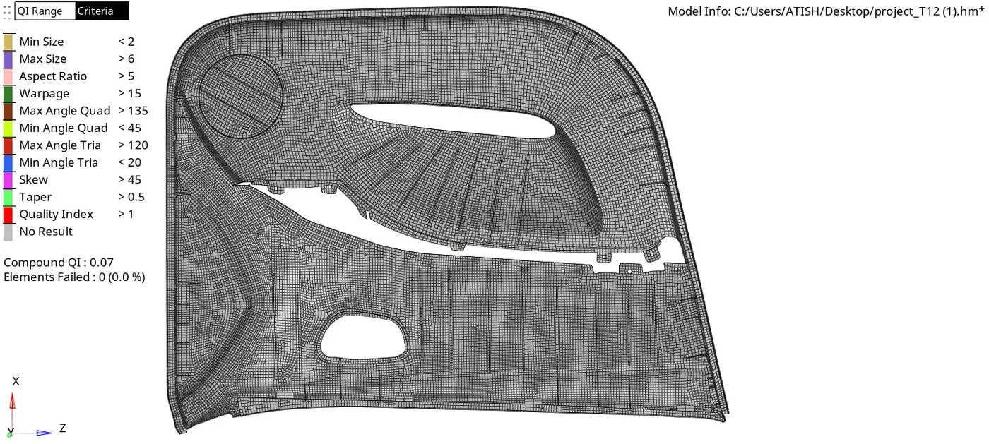
Fig - side door meshed
Step 6: Assigning the thickness
The final mesh obtained had to be assigned with the thickness value. To do that
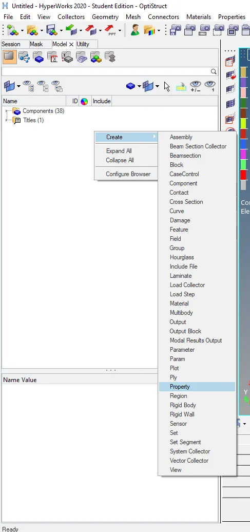
- Create the property id each for all the components having the different thickness.
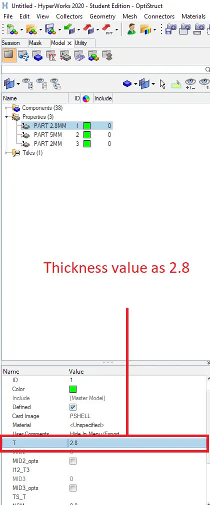
- Insert the thickness value inside the property card for the component
- Go to the component name>right click >assign > property. Choose the correct property card that has the required thickness for the particular component.
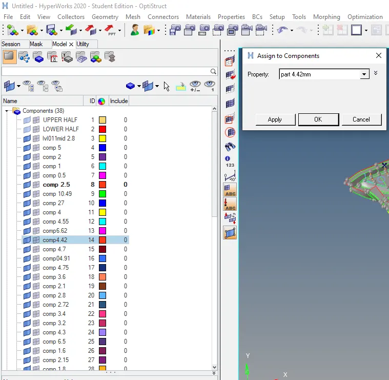
- Switch the shell representation to the 2D detailed thickness shell.
- Check with the parent surface if the glitching between the surfaces is happening.
Results :
The total number of elements formed for the side door panel were 33395 out of which the number of tria were 511 i.e 1.5 % and the rest were quad elements.
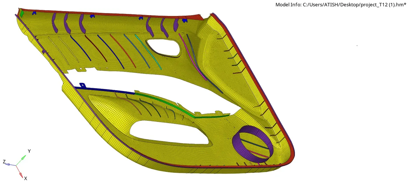
Fig - Unthickned 2d shell element side door panel
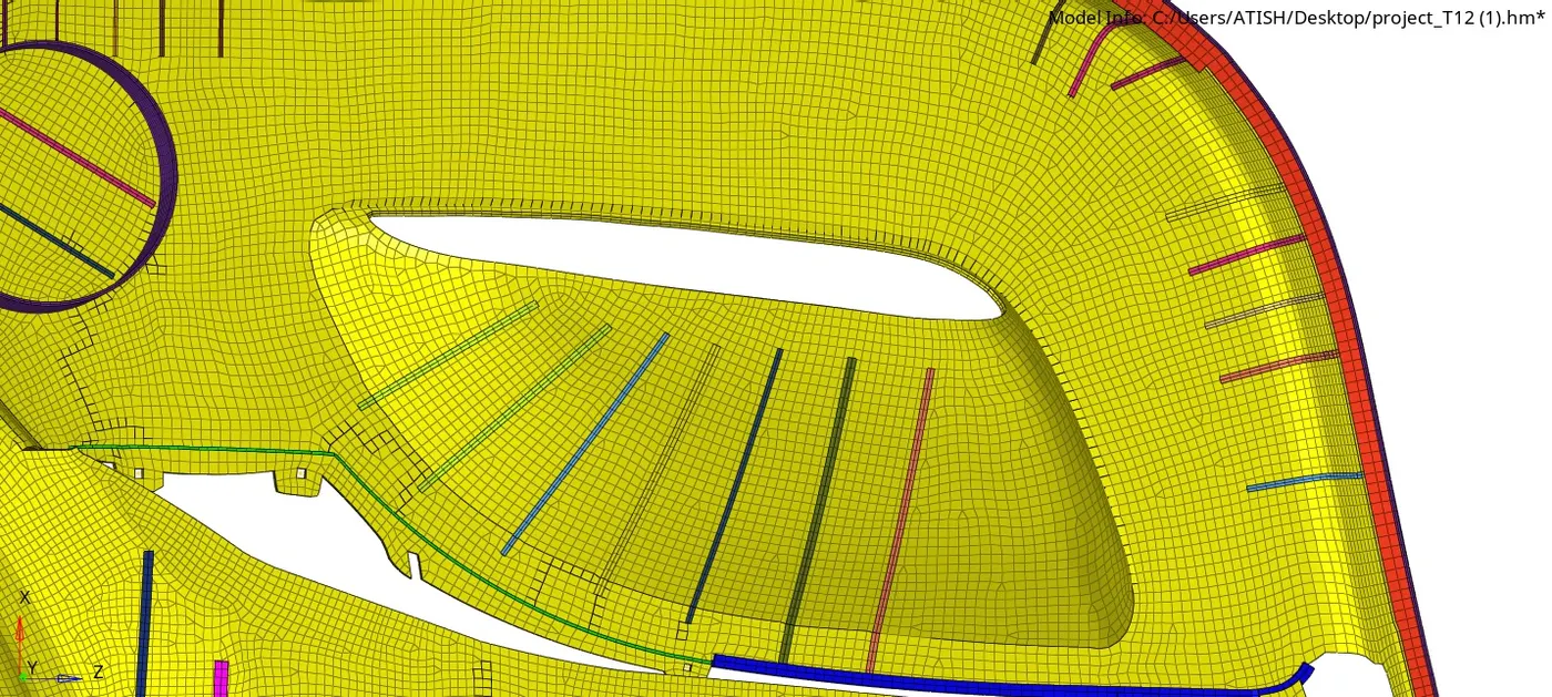
Fig - After applying thickness
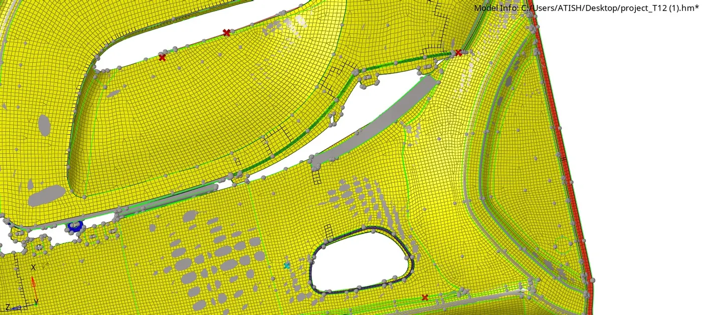
Fig - Glitching between parent surface and shell elements
Conclusion :
The side door plastic model mid surface is extracted properly followed by the meshing and assigning the thickness. The certain regions like docks , mounting rivets
were not captured because they were considered for solid meshing and it's difficult to establish the connection between the solid and 2D shell mesh .