Side Door Mesh by using Hypermesh
AIM :
To Extract a Mid-Surface and Mesh Component with given Quality Criteria values and assign thickness for the FE Model.
OBJECTIVE :
Follow the Quality Criteria and mesh the following component and assign thickness:
Target Element Length = 4mm
| S.N | Quality Criteria | Value |
| 1 | Aspect Ratio | 5 |
| 2 | Skewness | 45 |
| 3 | Warping | 15 |
| 4 | Taper | 0.5 |
| 5 | Min. Length | 2mm |
| 6 | Max. Length | 6mm |
| 7 | Min angle Quad | 45 |
| 8 | Max angle Quad | 135 |
| 9 | Min angle Tria | 20 |
| 10 | Max angle Tria | 120 |
| 10 | Tria % | 10 |
PROCEDURE :
1. Import the given Model in Hypermesh by using the Import option.
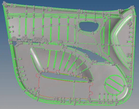
Fig: Side door model
Mid Surface :
2. Creating a mid surface for the component by using Geom-->mid surface option and Set offset type in extraction option subpanel and select the surfaces and Click extract in auto extraction subpanel.
3. By using another method, Go to Geom-->surface edit-->offset option and select the surface to offset and assign the thickness and click offset.
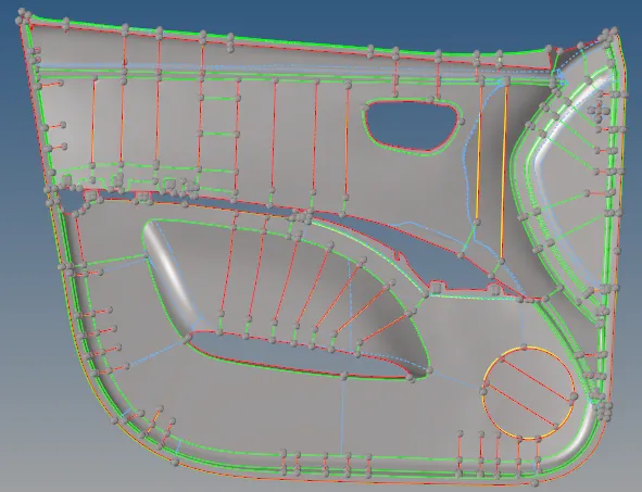
Fig: Side door Midsurface
Geometry Clean up :
4. After creating a mid surface, Clean up the Geometry for the given component.
5. Toggle the unwanted lines in the Geometry by using Geom-->quick edit-->toggle edge option.
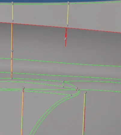
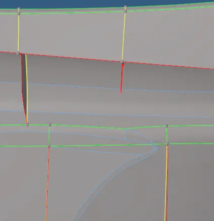
Fig: Before Toggle Fig: After Toggle
6. Replace two points into a single point by using Geom-->quick edit-->replace point option.
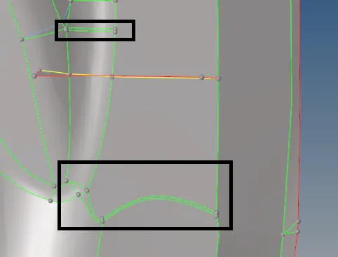
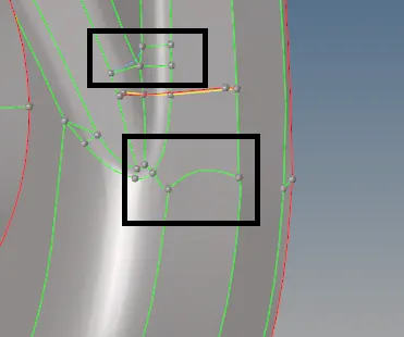
Fig: Before Replace Fig: After Replace
7. Split the Surfaces by using Geom-->quick edit-->split surf-node or split surf-line option.
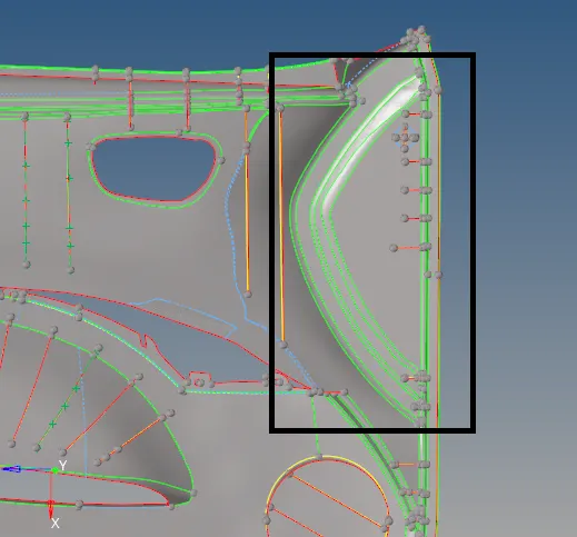
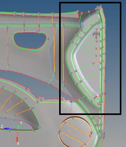
Fig: Before Split Fig: After Split
8. Go to Geom-->quick edit-->add or remove point option and remove the unnecessary points.
Meshing :
9. After Creating a Mid surface and Geometry Clean up, Start Meshing for each Component separately.
10. Go to preferences-->criteria file settings option and Set target element size and given quality criteria values and click apply.
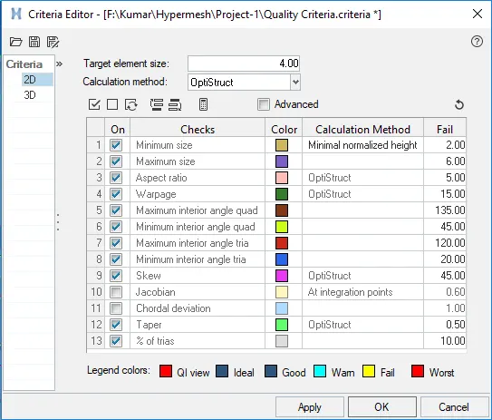
Fig: Quality Criteria
11. Go to 2D-->automesh-->size and bias option and element size as 4 and Select the surfaces and click mesh. Do meshing surface by surface to get proper mesh flow.
12. After creating Mesh, remove the trias and quads in the fillet region by remeshing the component.
13. Go to 2D-->rebuild mesh option and select the elements and click rebuild to rearrange the mesh component.
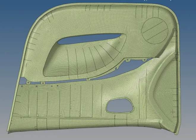
Fig: Side Door Mesh
Quality Checking :
14. Go to 2D-->quality index option and Check any quality issue and clear the issue by using the Cleanup tools option.
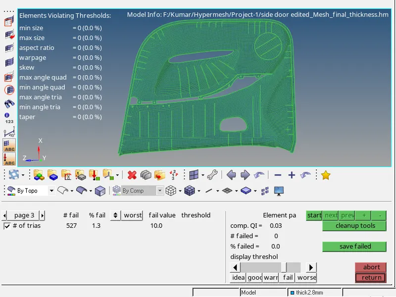
Fig: Quality Criteria with Element Parameters
15. Go to 2D-->Smooth option and select the elements and Smooth the elements.
Finding Connectivity :
16. Go to Tools-->edges option and select all elements and set tolerance value and click find edges.
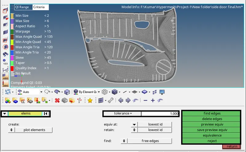
Fig: Checking Elements Connectivity
17. If there are any edges that are not connected, Click the preview equiv option to preview the unconnected elements and click equivalence to connect the elements together.
Assigning Property(thickness) :
18. Go to Model-->Right click-->Create-->Property option and assign the parent body thickness to the mesh component.
19. Go to Components and assign the property for each component.
Fig: Assigning Property for each Component
20. Change 2D Traditional Element Representation into 2D Detailed Element Representation to display the actual thickness of the mesh Component.
RESULT :
In the given Side door model, extracted Mid-surface and then meshed. Parent body thickness is assigned to the meshed component by created Property and assigned to the separate component.
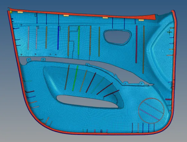
Fig: Side Door Mesh with suitable thickness