2D Meshing on Vehicle Door Trim Using Hypermesh.
AIM
* 2D Finite element meshing on the Vehicle Door Trim Using Hypermesh.
METHODOLOGY
- Import the model in Hypermesh using Import option.
- Perform topology and geometry clean upon the geometry eliminating all the errors in the geometry.
- After visualizing the model it is recognised as a plastic model and shell meshing is followed here due to its less thickness.
- Extract Mid-surface from the actual geometry.
- Perform the cleanup operation on the Mid surface if required.
- Deploy mesh on the extracted mid-surface as per given Quality criteria.
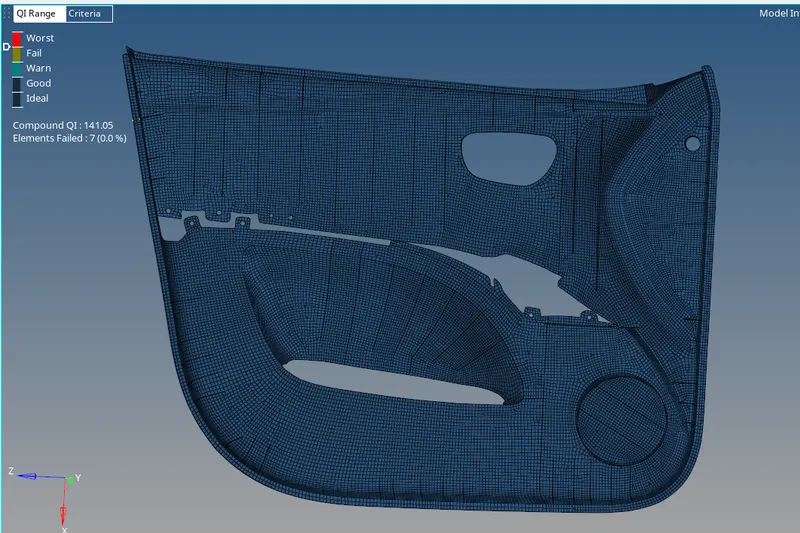
- Check for any Quality failing elements and eliminate them using cleanup tools.
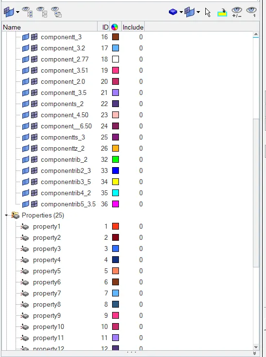
- Save the FE into different PIDs and assign thickness to it.
DOOR TRIM

An interior component attached to the inner side of the door. This product does more than merely improve the appearance of the vehicle interior. Rather, it is a vital module component that creates a more comfortable interior by providing a variety of accouterments and functions.The door trim panels are key components making up the interior space of a vehicle. The main materials used include kenaf, which grows year round and has excellent CO2 absorbing properties, and plant-derived plastic, making them environmentally friendly as well.
PROCEDURE
*The CAD model has to be pre-processed before solving and Hypermesh software is used here to mesh the model.
*Model dimension, Geometry editing and complexity reduction is done in Hypermesh
1.GEOMETRY CLEANUP
*Import the model using import option.
*The given model should be analysed properly.
*The model seems complex as it consists of many ribs.
*Apply topo on the selected view and check up the geometry.
*Unchecked faces or triple cons are eliminated as a part of clean up.
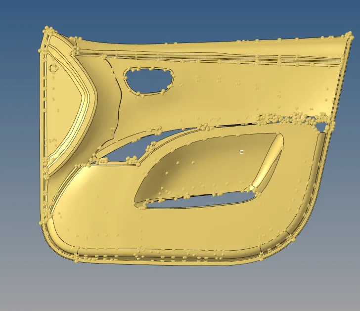
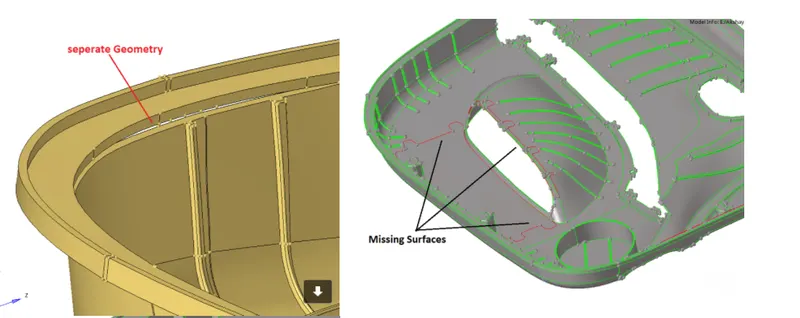
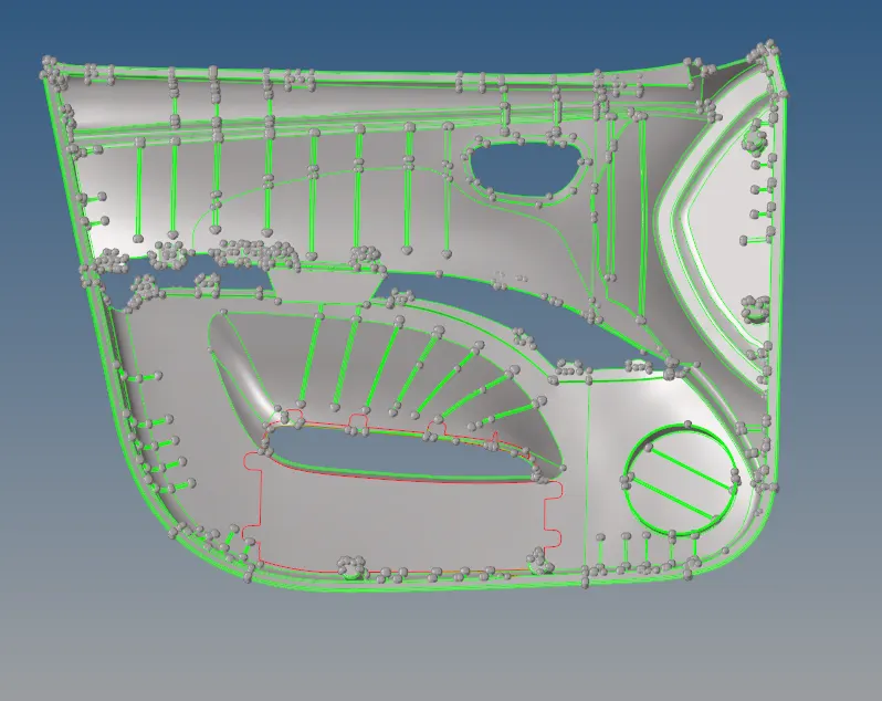
The surfaces having geometrical errors will be represented by different colors in the Hypermesh Workbench.
* The red lines are single cons which represent that the geometry has some errors or lines with no connection to its adjacent lines.
* The green lines always indicates the connecting surfaces and in this model all the geometry lines should be represented in green lines.
* The yellow lines indicate the triple cons means more than two lines are in contact with each other.
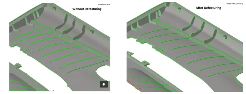
Defeaturing
* Before extracting midsurface some of the features are defeatured to capture them more accurately. The RIBs with the fillet are difficult to capture manually due to its complexity and so defeature option is used in such cases.
MIDSURFACING
There are two methods for MID surface extraction,one is Auto midsurface extraction using midsurface panel from the geometry deck and the another one is manual one using offset option. Usually for more complex geometry Engineers go with the Manual method to capture detailed features over the model body and It's an Engineer's job to decide with which method he/she should go for better results.
*Midsurface can be obtained manually and automatically by using Midsurf command.
*Here, midsurface is generated for every component of the model using offset under surface edit option under Geometry deck.
*Midsurfacing of main model except some features is generated using offset as shown below.
*When it comes to features linelist option in lines under geometry deck is used to obtain the midplane.

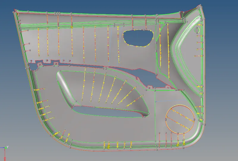
Defeaturing/ toggling MID surfaces
* After extracting the midsurface of the model the geometrical errors present in the midplane is cleaned up using quick edit option
* Before going with the mesh deployment its necessary to do appropriate defeaturing over the MID surface obtained as the unnecessary construction lines should be removed or altered to get a better mesh flow throughout the model.
3.MESHING
*A mesh is a network that is formed of cells and points. It can have almost any shape in any size and is used to solve Partial differential equation.Each cell of the mesh represents an individual soultion of equation which, when combined for whole network,results in a solution of entire mesh.
*On meshing the model element size must be consistent and here as per the given details, it is 4 and here it is followed initially before geometry cleanup.
*Quality criteria should be assigned according to the given values.
*In quality criteria aspect, skewness, angle, minimum length, maximum length, warpage and aspect ratio is considered here as shown below.
*Check all the fillets before meshing to make sure it is under the minimum length given for meshing.

QUALITY CRITERIA
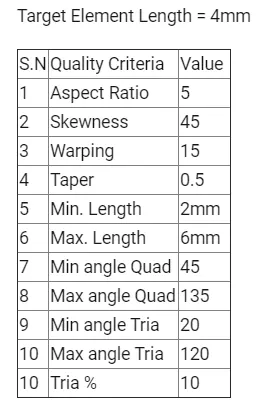
* For a better understanding of quality failing elements, the quality index sub-panel from the 2D mesh panel is used as shown in the below image and it helps in cleaning up the failing elements using cleanup tools.

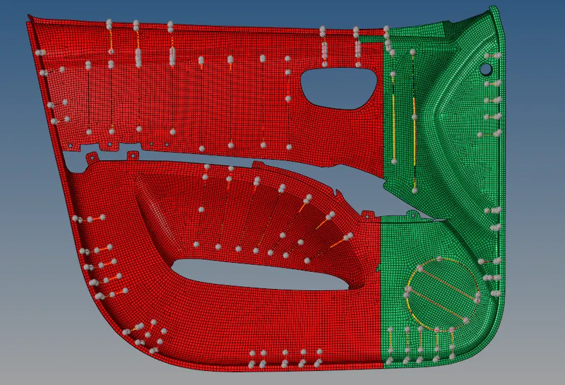
CONCLUSION
*In preprocessing meshing is significant as it helps in the flow of stress evenly throughout the model.
*A smooth mesh is better in weight distribution analysis.
*Meshing is done in the midplane of the model and not in the parent geometry.
* Mesh refinement may improve the modeling and analysis of regions with stress concentrations, extreme force gradients, member connections, etc.