Shell element meshing over the Vehicle Door Trim Using Hypermesh.
Aim:- 2D Finite element meshing over the Vehicle Door Trim Using Hypermesh.
Methodology:-
- Import model from its respective location. This model may be the step/IGS /hm file.
- Perform topology and geometry clean upon the geometry, Identify and remove all possible errors in the geometry.
- After visualizing the model, we get the idea about which category the model will fall into. Like sheet metal/plastic/casting part. So, we can choose the meshing option accordingly.
- For the sheet metal part which has a thickness of less than 6 mm or measurable thickness, we can go with the Shell Mesh option.
- For casting / plastic part if the part having a thickness of more than 6 mm, solid meshing is preferred.
- Extract Mid-surface from the actual geometry.
- Again, perform the cleanup operation on the Mid surface if needed.
- Deploy mesh on the extracted mid-surface as per given Quality criteria.
- Check for any Quality failure and remove them.
- Save the FE into different PIDs and assign thickness to it.
The model we have got is as follows,
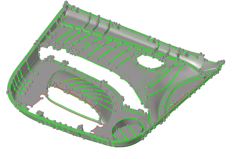
Door Trim. An interior component attached to the inner side of the door. This product does more than merely improve the appearance of the vehicle interior. Rather, it is a vital module component that creates a more comfortable interior by providing a variety of accouterments and functions.
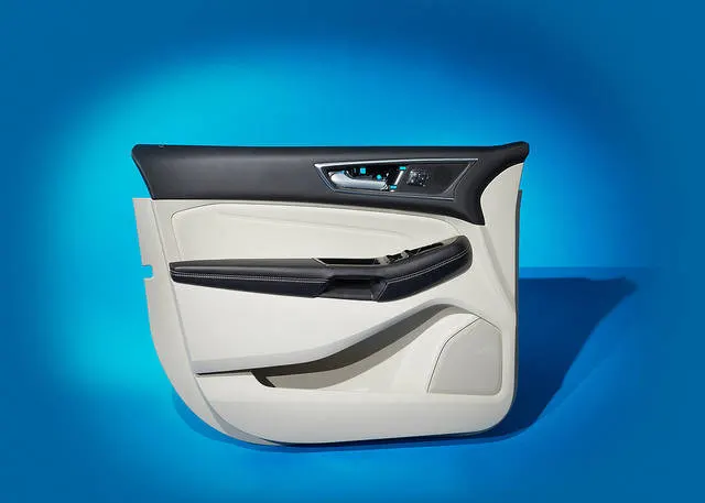
it's also the cover to hide the power window motor and have a different section to mount different vehicle electronics.
Quality Criteria
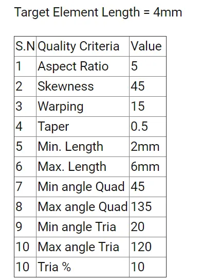
I had followed the Quality parameters which are mentioned in the above image.
Steps:-
-For This Project, I got a Plastic Trim of a door as we know The plastic component has a variable Thickness. My role here is to clean up the geometry, extract the MID surface, and deploy the mesh on them.
-As you can see in the above image the substrate having nos of RIBs which might have different thicknesses as per their applications. Also, the components data is extracted using the 3D scanner that's the reason there are some missing surfaces and unwanted geometry capture. So our job is to identify it and repair it to the level where we can extract the MID surface.
-After importing the model, the first thing I did was check for solids in the Geometry and delete it. After that performed topo (Topology). The topology just eliminates the un-necessary geometrical distortion (geometrical irregularities/ missing surfaces/ Intersecting surfaces etc.) in the model. This distortion is mainly due to the fact that the models are getting imported from different CAD design software. You can find this option to clean up the geometry in the "geom" panel. [geom--> quick edit]
How to identify Geometrical errors visually ??
-The surfaces having geometrical errors will be represented by different colors in the Hypermesh Workbench.
-The red lines are single cons which represent that the geometry has some errors or lines with no connection to its adjacent lines or surface are not available there.
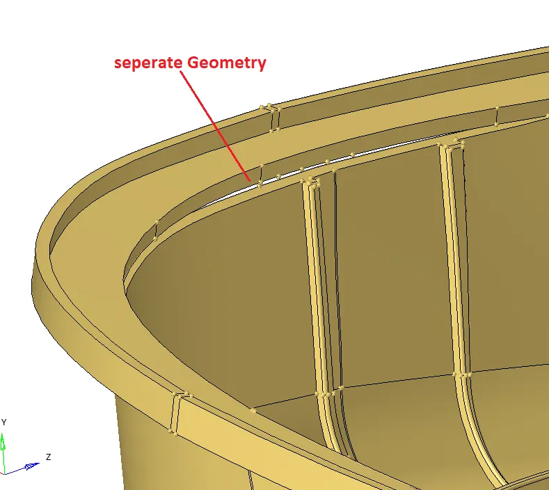
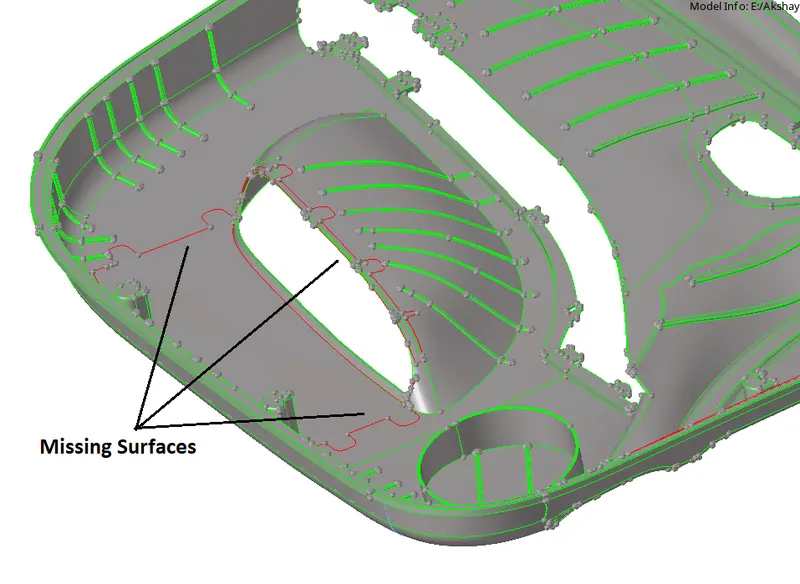
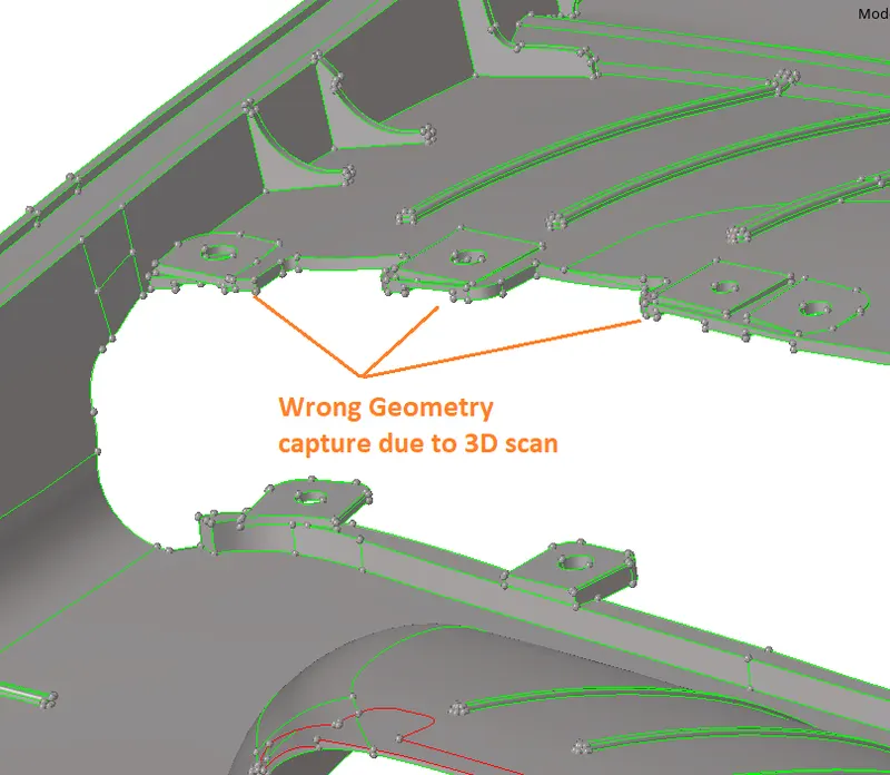
-The green lines indicate the connecting surfaces. In the imported model, all the geometry should have represented by green lines.
-The yellow lines indicate the triple cons means more than two lines are in contact with each other. For the plastic components, it is ok to have triple cons as it contains rib likes structures but in the sheet metal part, it is not acceptable as they have uniform thickness throughout.
Let get back to our main topic, I had checked the model for the Geometrical errors and I have found Nos of errors and missing surfaces to take care of. Some of them have complicated curves in geometry but the good thing is the only one side of such surfaces is missing and the other side is can use for MID surface extraction using the offset option.
I had used the "Geom" panel to clear out the errors ar stitch the surfaces.
I had used Panel box options from the panel area for geometry clean up.
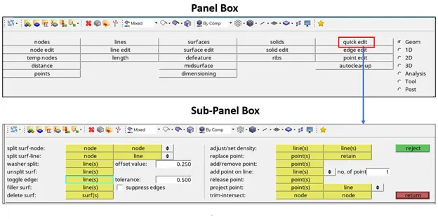
“Geom” option from the panel will help to get rid of many of the geometry related errors. There are so many options available for geometry clean-up like nodes, lines, surface, solid, Defeature, etc. which would help us for initial cleanup.
In the above image the “Subpanel box” is come under the “quick edit” option. As you can see that with the quick edit you can perform the basic clean operation. Like “Toggle edge” will connect the nodes/ lines within its tolerance zone, we can either increase or decrease the tolerance to remove the respective error. Then there is the “add/remove point” option which would remove the unnecessary points from the geometry.
Defeaturing/ toggling MID surfaces
I had used the Geom deck to defeture some of the features to capture them more accurately. The RIBs with the fillet are very hard to capture by manual as well as the Automatic method but with the Defeaturing, we can repair the damaged surfaces and geometries before extracting the mid surface. It will help us while extracting the MId Surface.
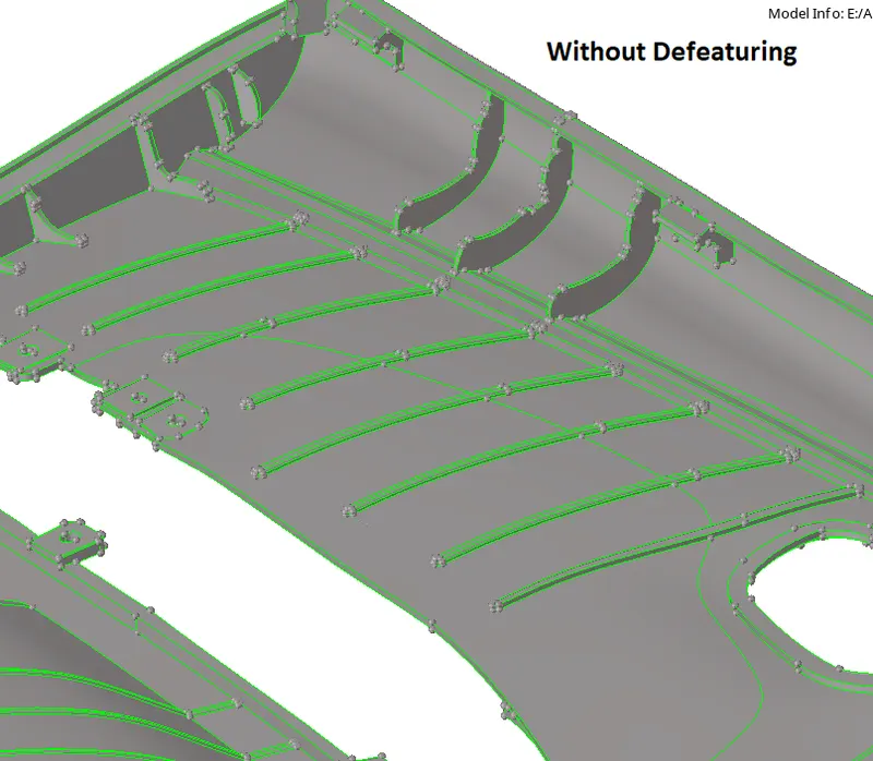
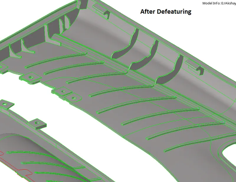
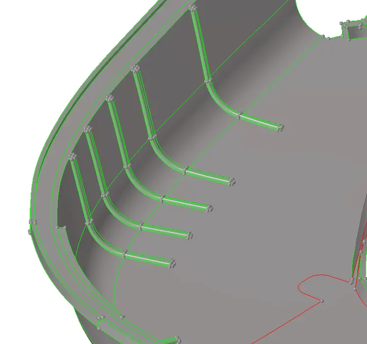
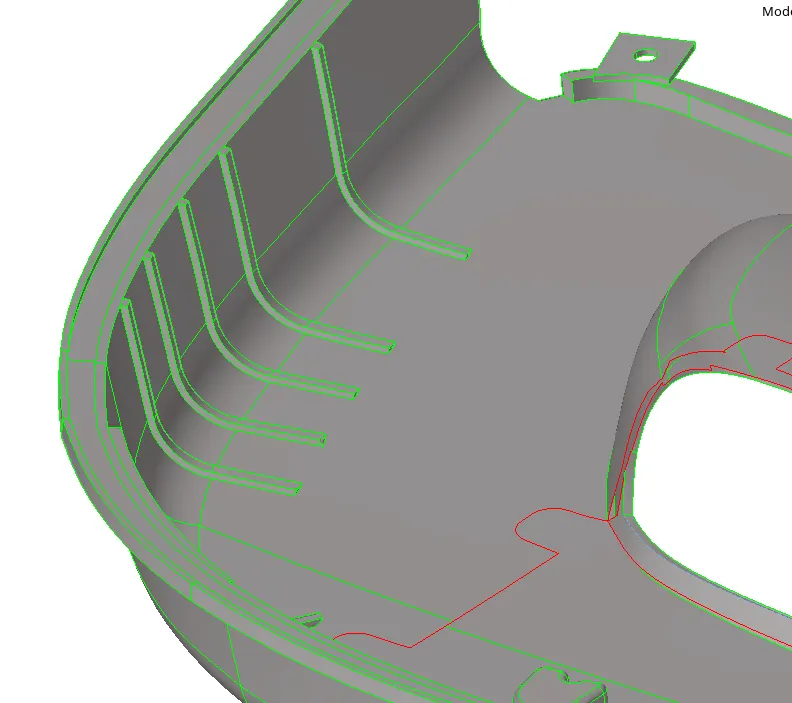
In the above images, you can see the difference between before and after Defeaturing.
MID surface extraction.
- After Defeaturing the next step was Mid-surface Extraction.
- There are two methods for MID surface extraction one is Auto midsurface extraction using midsurface panel from the geometry deck and another one is manual one by using offset option. For more complex geometry Engineers go with the Manual method to capture detailed features over the model body. It's the Engineer's job to decide with which method he/she should go for better results.
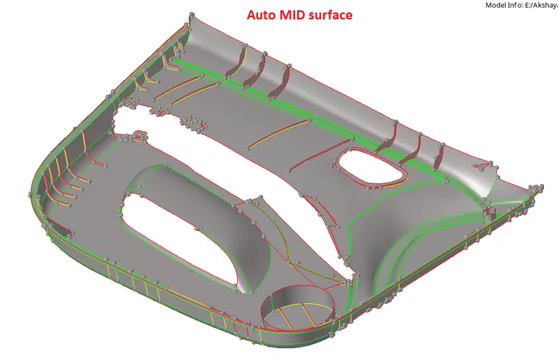
Auto MID surface --> geom--> midsurface

I had used the “midsurface” option which leads me to the sub-panel of the midsurface option as you can see in the first image. Then there was a data tree which is showing the new property as midsurface in the second image (red box).
We only have to select the geometry for which we want to extract the mid surface and we will get one. There are different sort of MID surface options are available.
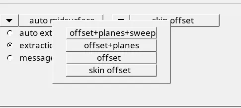
I had gone with the first option which will identify the places where a formulation of a plane or sweep surface can be used as a middle surface. A middle surface is constructed at the remaining places in the model, for example, in the places where planar or sweep surface formulation cannot be used as a middle surface, the offset surface algorithm is used to take the MID surface by the offset method.
But by observation, I conclude that this method is not good for all the geometries. The component we have got already has some surfaces missing and the geometry is also not that good. I had to try this method and it failed with CRASH.
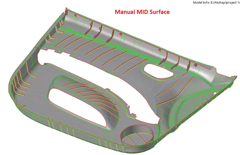
Manual MID surface --> geom--> midsurface

-Under this method, we have to select the surface part by part and make an offset of it.
-As this model is too large I have decided to Trim this component into Nos of part and save it in Different Component ID, For Rib also I had done the same. with offset, we are able to capture the feature very well and with better accuracy.
-As you can see in the panel screenshot above there is an option for surface selection than with how much distance you want to do offset. the main thing here to notice is we are just offsetting the outer surface of the geometry by some defined value so make "Duplicate" of it is the important thing. Also, the vector direction is important for that we have an option named "vector normal and reverse normal" to identify and reverse the vector if it's not in the desire offsetting direction.
Manual and Automatic MID surface Result
Defeaturing/ toggling MID surfaces
-With the same method, I had extracted the midsurface of all three models. After extracting the mid surface, I had checked for any geometrical error in the mid surface also.
-We can use the same set of tools that we had used for geometry clean-up. [geom --> quick edit]
-Before going with the mesh deployment its necessary to do appropriate Defeaturingh over the MID surface as sone construction lines may cause the problem for the Mesh and mesh flow
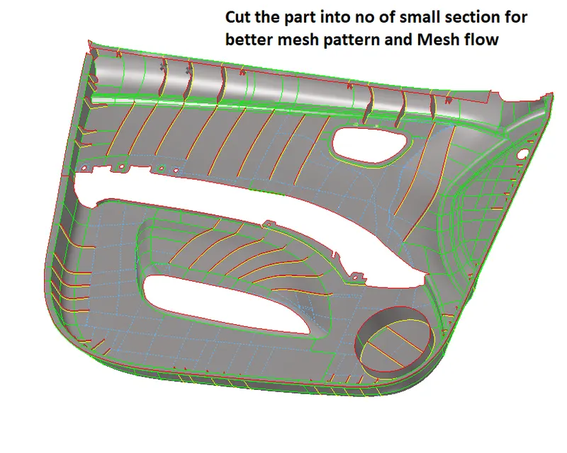
-toggle out the bend line and captured it by one line only because it's not satisfying the min length criteria in some areas near the bend Also, over the corners, it will show the element failure as well as introduce tria elements due to the curve nature of the geometry.
-You can see in the above image I had toggled out most of the construction lines and make my own lines to control the mesh flow. In the model, I had deleted no. of construction lines which are not important.
2D Finite Element Meshing
-Meshing Is the process of Discretization of the continuous system from an infinite degree of freedom to a Finite Degree of freedom. In this method we put mesh over the component means we divide the large system into the small elements/ surfaces. Doing calculations over the smaller surfaces will give more accurate results, and we can interpolate the result which we would found over the smaller nos of elements groups over the entire domain.
-In short by deploying mesh over the components we divided its surface into smaller surfaces and restrict its DOF.
-There are separate Panels and sub-panels available in the Hypermesh to deploy different sorts of mesh-like 1D, 2D, 3D. For this project, as we are working on the Sheet-metal component we don't need 3D meshing. Usually, sheet metal components or components having a thickness less than 6mm falls under the 2D meshing.
2D --> automesh

- the above image is of an automesh panel which is the Sub-panel of a 2D panel. I had used Target length as 4 mm not 5 mm.
- you can set the target length and the type of mesh. Make sure you have selected the surface. After hitting the mesh button, the mesh will automatically get deployed on the mid surface. The deployed mesh quality good or not it's the engineer's job to clarify that and give the best mesh possible. for that there are nos. of mesh edit options are available in the 2D mesh panel.
- I am using a "mixed" type of mesh here as it's considered to be good for structural Non-linear analysis.
Errors In the Mesh
-For a better graphical understanding of quality failure we can use the quality index sub-panel from the 2D mesh panel. the panel is shown in the below image. We can also clear out the quality failure using the cleanup tools.

I had used remesh and this cleanup tool to clear out the Element failure.
Release the Mesh from the Geometry and Thickness Definition
-Releasing the mesh from the geometry is a very important step as only the mesh will go further for analysis and not an actual geometry/ MID surface.
-For that first, we have to create a new Dummy Id where we can transfer/move the elements. I had created the three IDs with the name and thickness based.
-To move the element toward the new component ID there is an option named organize in the Tool panel.
Tool --> organize

-We only have to select the elements we want to move over a new ID and set the Dest component (Destination) and hit the move button. As you can see in the above panel I have select Inner Extract Mesh as a destination ID so all my respective elements are gets move over that ID.
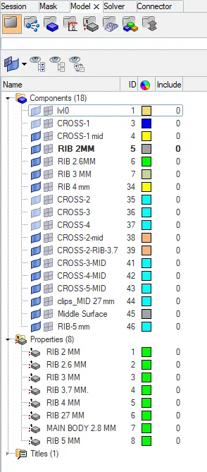
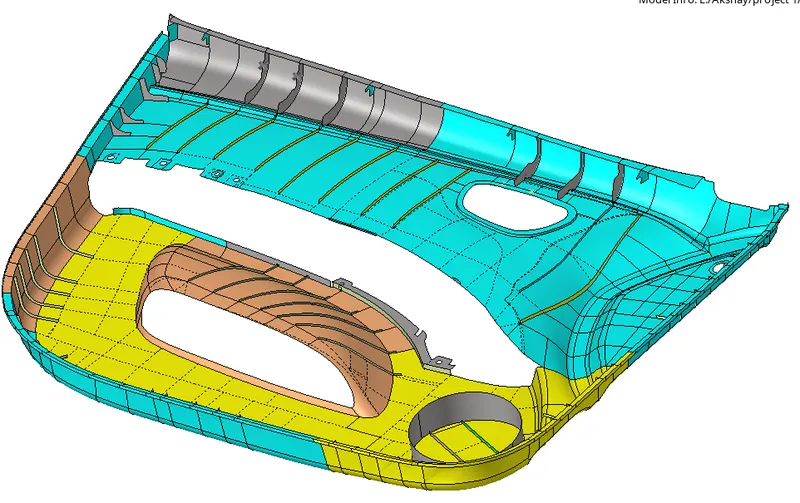
You can differentiate between the different sections using color code.
For thickness assigning we have to Define the property IDs for all these components, and in there we can define the appropriate thickness then we have to assign that property to the respective components/ mesh.
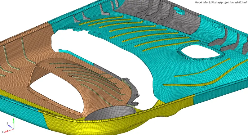
-After that, we have to check on the "2D Detailed Element Representation" option to see it in actuality. As you can see in the above image the thickness is getting assign to the shell elements.
The final result in the Quality Domain
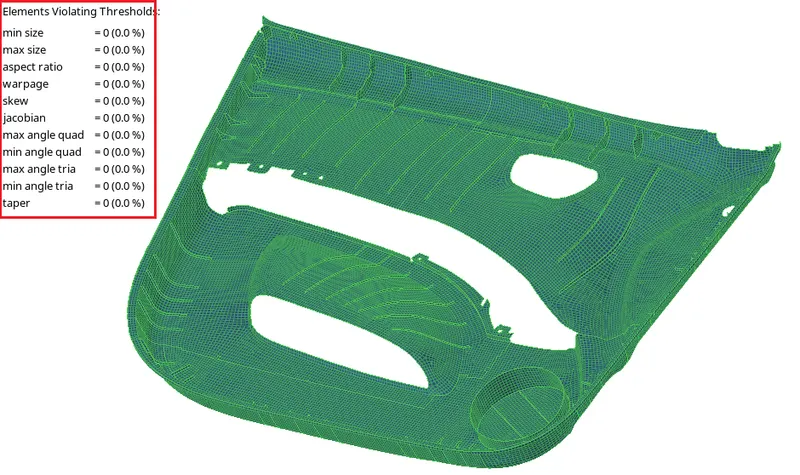
There are NO fail elements in the MODEL.
Conclusion
-To perform any kind of analysis meshing is important as it helps to restrict the DOF.
-Smoother the mesh better the Force distribution during analysis.
-PIDs should be defined in each component as per the thickness or material.
-For the sheet metal part which has a thickness of less than 6 mm or measurable thickness, we can go with the Shell Mesh option. For casting / plastic part if the part having a thickness of more than 6 mm, solid meshing is preferred.
-We can't perform Analysis on the actual 3d model either it is solid sheet metal or plastic, we have to convert the model along with its feature into the solver and post-processing software adaptable format and HyperMesh (pre-processing) is one of the platforms for it.
-Only the Mesh (FE) is passed down for the analysis, not the actual Geometry nor the mid-plane.