Week 12- Final project
AIM- Development of a Door Trim panel.
INPUT GIVEN-
1. Class A Surface
2. Bush
3. Dog house drawing
REQUIREMENT
1. Tooling Axis using bisecting method.
2. Class A surface
3. CLass B surface
4. Class C surface
5. Closed surface's
6. Draft analysis
7. Closed surface bracket supports.
8. Rib & screw boss design
9. Dog house design
10. Given master section flanges and brackets design
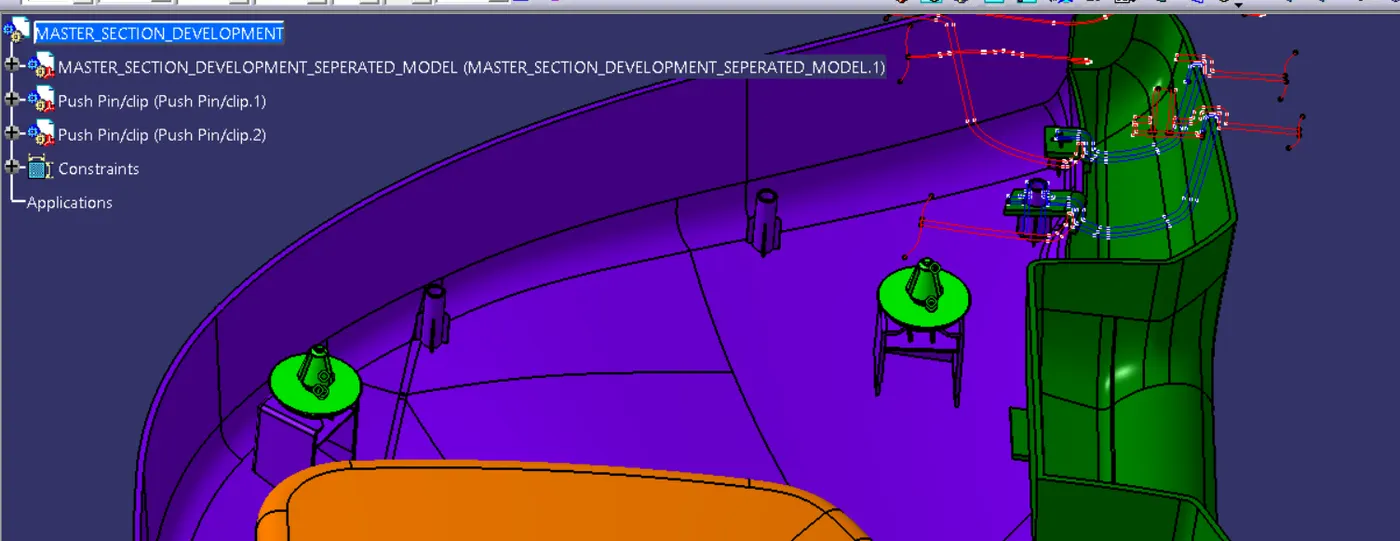
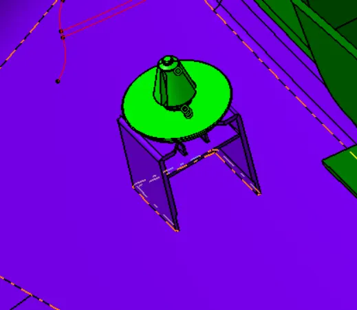
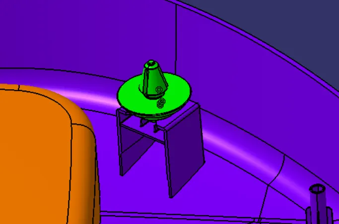
11. Bush assembly
12. Result & conclusion
About
In the design the necessory styling data received from styling team if any correction in data get update/highlight with same team. While design have to ensure that the necessory requiremet first for example class A surface, master section, tooling axis using bisecting method & draft analysis for suaitable checking.
1. Tooling Axis using bisecting method.
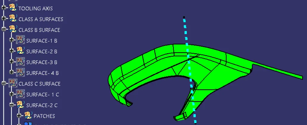
Its direction in which the mold or cavity opens is the tooling axis. Also its predefined the fesibility of component very easily for tooling following points to be consider.
- First ensure the class-A surface is properly joined & has no discontinuity on it for this we use the boundry comman or joined command.
- Analysis of the given model at which tooling axis may clear all the direction.
- Choose suaitable surface for tooling axis.
- Example As in 3D view if we can see 2 holes and a flat surface, we can directly take the tooling axis perpendicular to that. But to be sure,let us analaze from all the views. The below images of the front side and top views shows the areas that we have to keep in mind while choosing tooling axis. As from X we cannot see one hole so we cannot take axis along this. In Y we cannot see any holes so here too we cannot take tooling axis. But in Z we can see 2 holes and flat surface so we can take tooling axis.
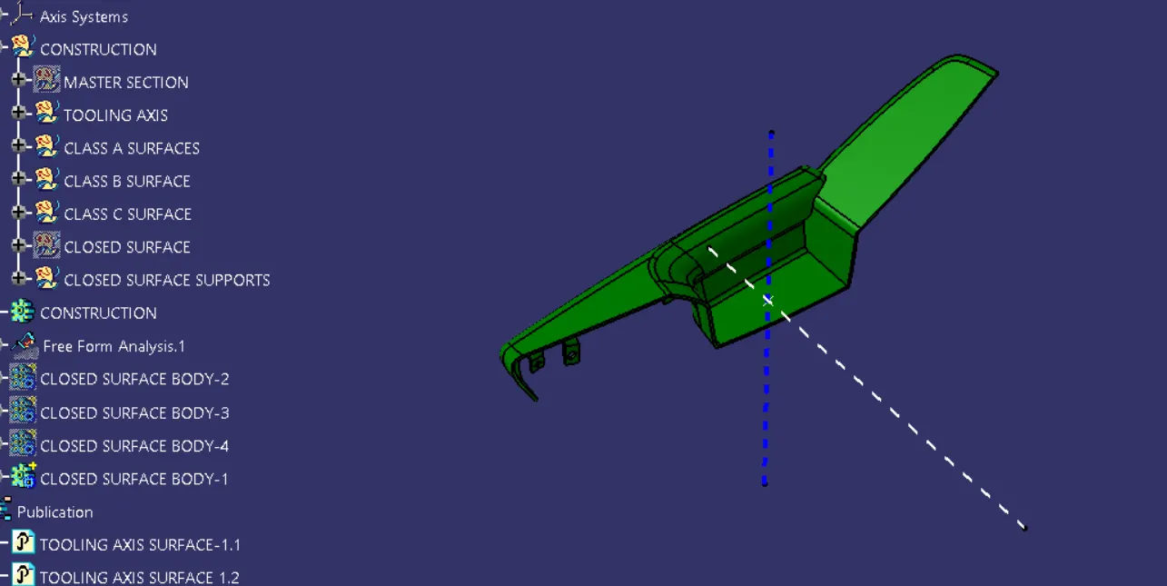
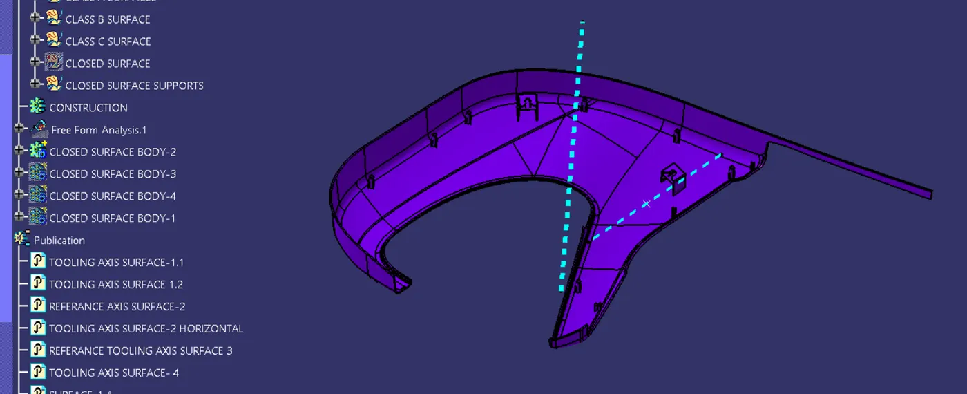
Surface-1 Tooling Axis Surface-2 Tooling Axis
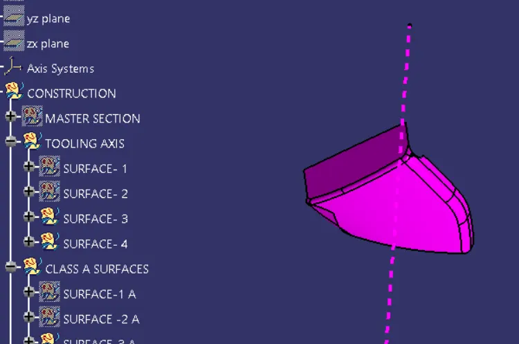
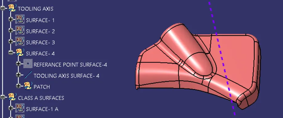
Surface-3 Tooling Axis Surface-4 Tooling Axis
2. Class A Surface
Its the referance surface is given by styling team but if incorrect surface is found then highlate with styling team for adequate Class A surface.
We have receive class A surface but in the same we are facing issues in class A surface-1. when we use offset value from class A surface 2.5 mm as per given thickness the discontinuty in class B observed. below picture shows Class A surface & disintegrity of class B surface.
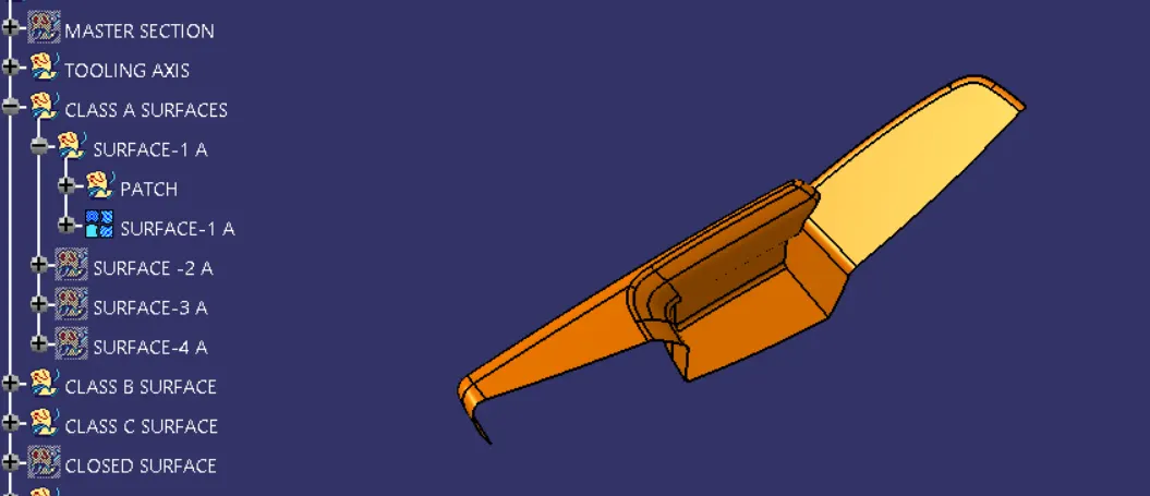
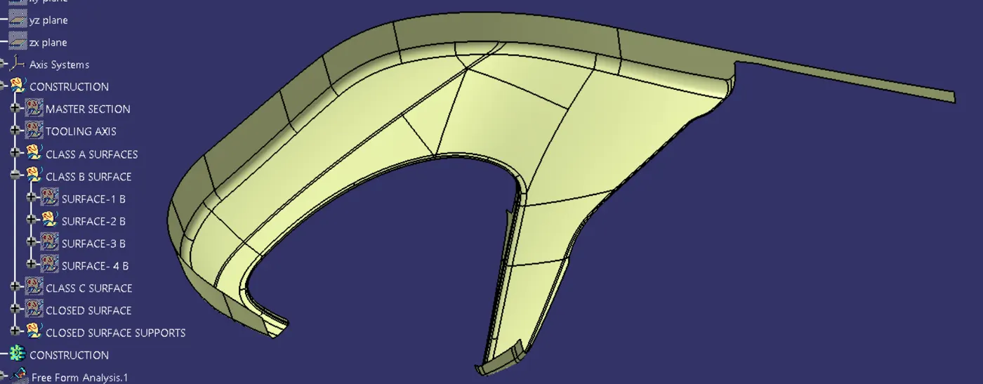
Class A Surface-1 Class A Surface-2
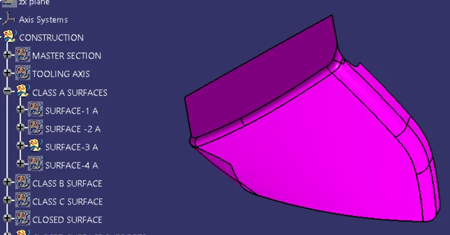
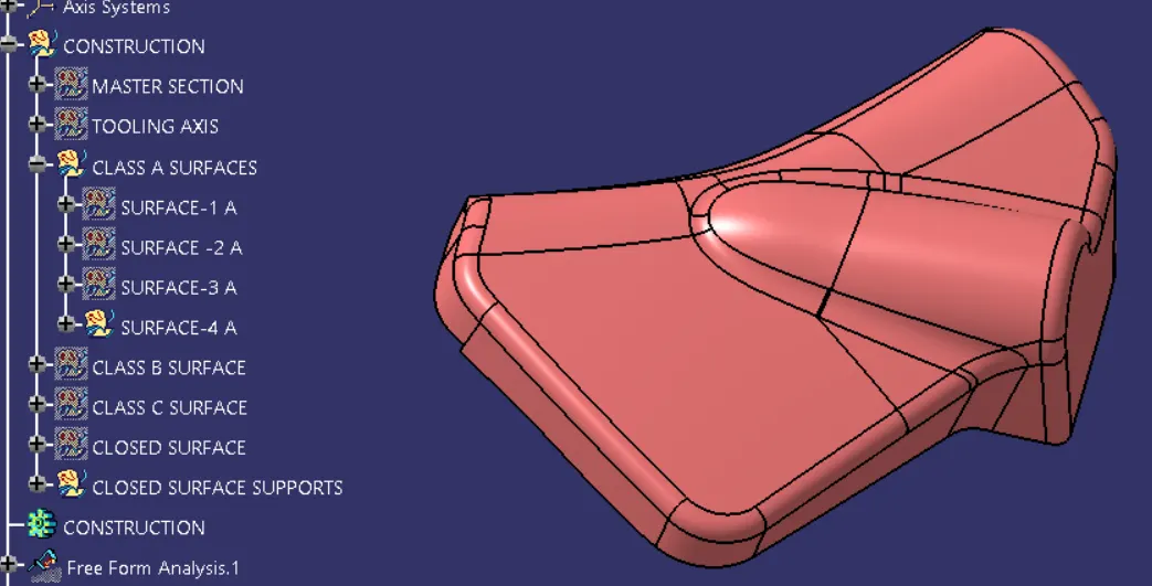
Class A Surface-3 Class A Surface-4
3. Class B Surface
Its the offset thickness value from class A surface.
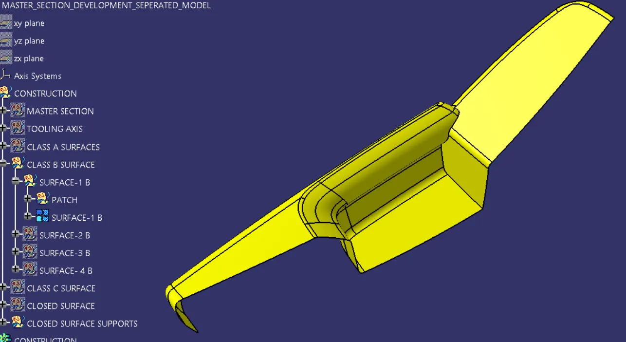
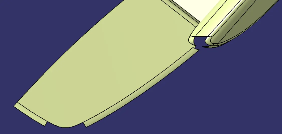
Class B Surface-1 Class B Surface Disintegrity-1
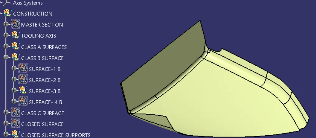
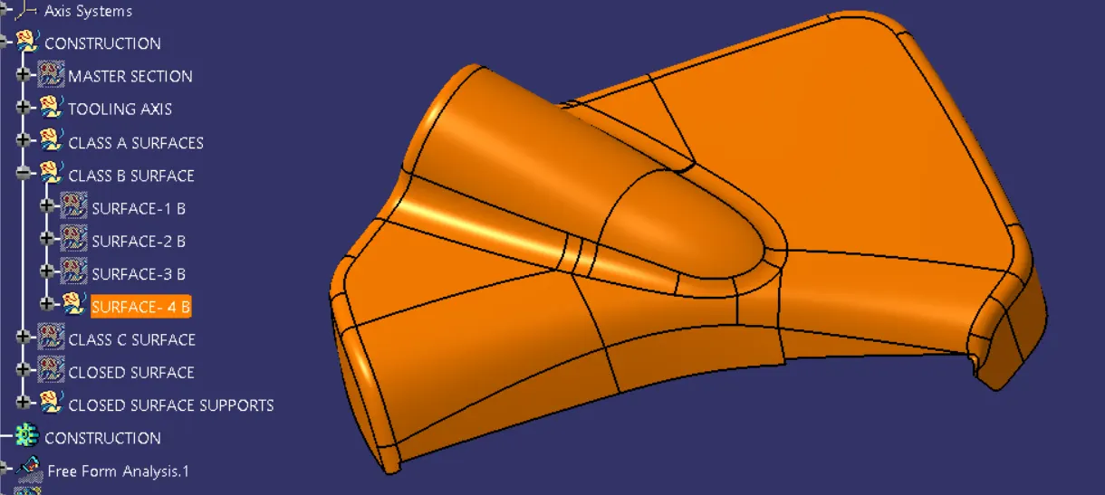
Class B Surface-2 Class B Surface-3
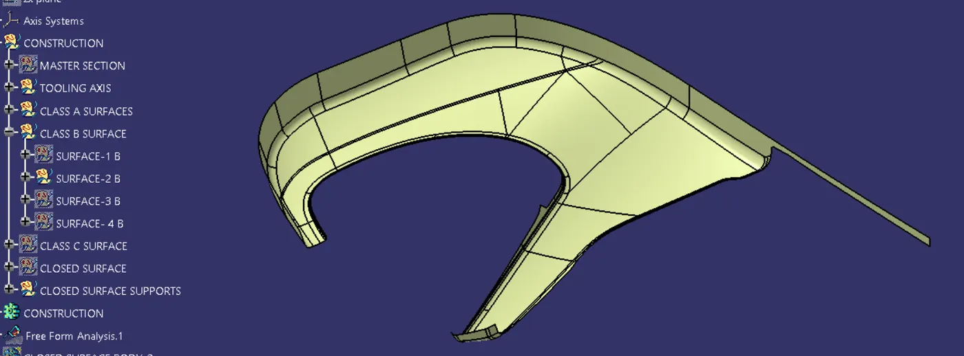
Class B Surface-4
4. Class C Surface
Its the intermidate surface of class A surface and Class B surface called class C surface. The class C surface is parallel to the tooling axis. Below pictures shows the surface 1,2,3 & 4.
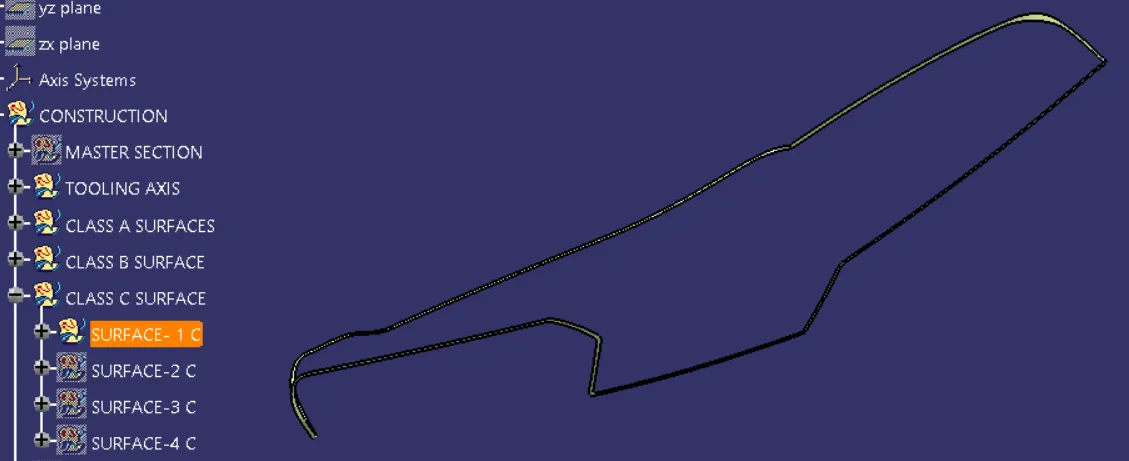
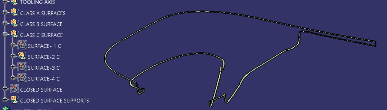
Class C Surface-1 Class C Surface-2
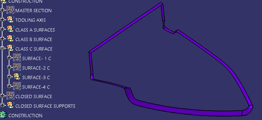
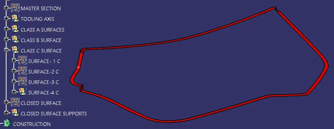
Class C Surface-3 Class C Surface-4
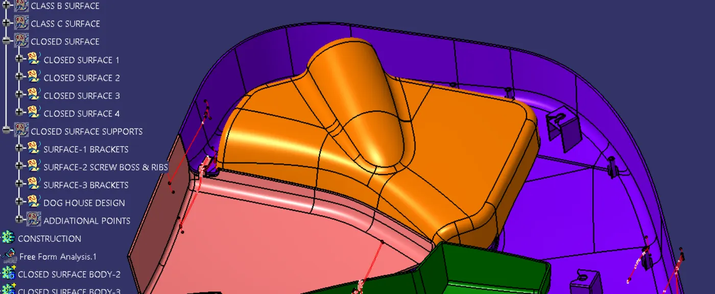
5. Closed Surface's
The surface class A, class b & class C surface are joined together colled closed surface.
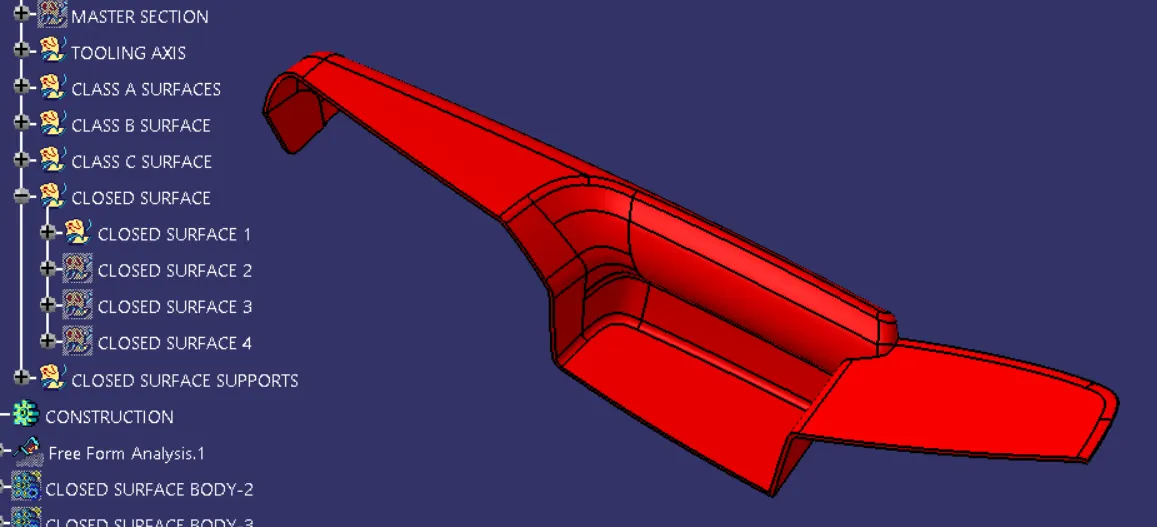
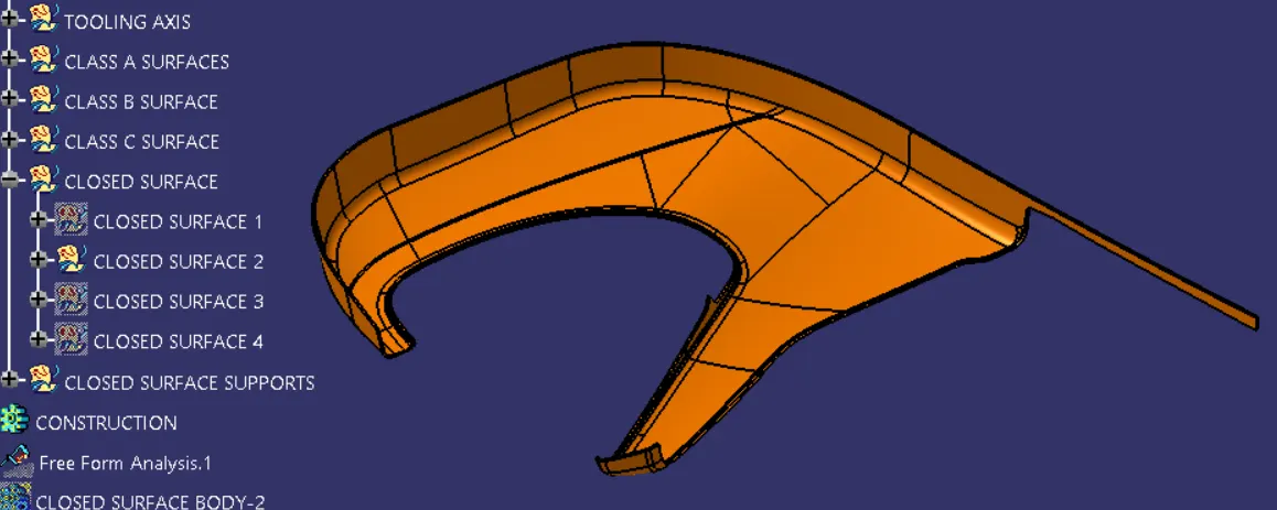
Closed Surface-1 Closed Surface-2
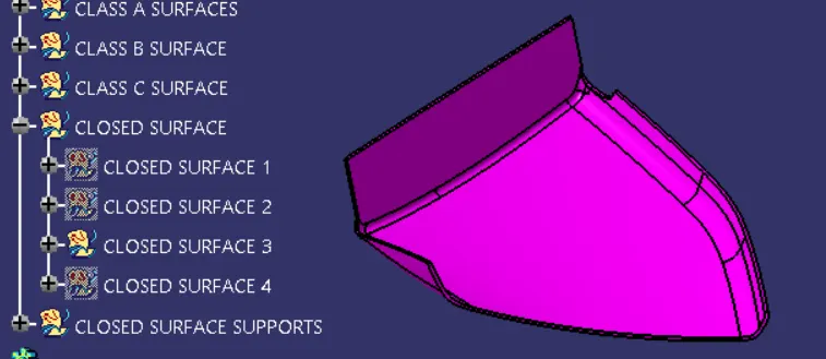
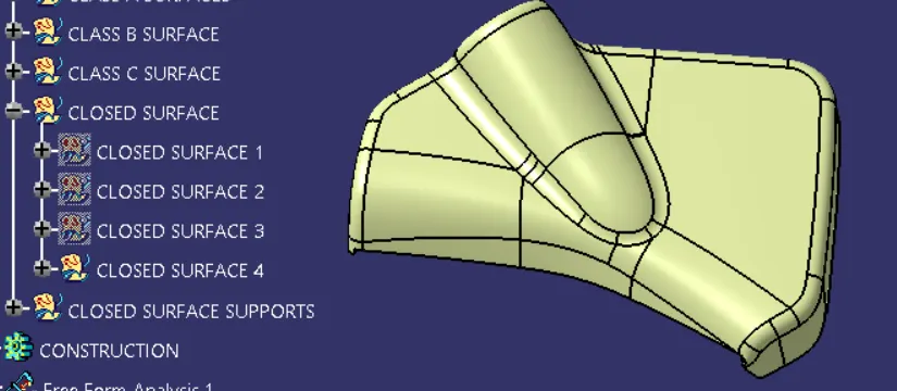
Closed Surface-3 Closed Surface-4
6. Draft analysis
Draft
The draft is the amount of taper moulded or cast part perpendicular to the parting line. draft angle are a desing consideration that makes it much easier for a part to release cleanly from a mould A draft angle is calculated as a degree measurment ( less often, an inch or millimeter measurment ) from vertical axis of a mould & it helps account of thermoplastic shrinkage. a partical reality of the injection moulding process for most materials.
Draft angles are generally a requirement of injection moulding design (though there are select few soft material, like nylon that can get away with angle of zero) The draft should be a part of the design manufacture and all stakeholders & contributors should be aware of its need at the out side of the design process. This includes product designers, design engineers etc & this allows considerations for desing requirement to be taken into account. Any draft is better then no draft.
Importance of Draft
By accounting for thermoplastic shrinkage during the cooling process, draft angle significantly reduce friction between the finished, cooled part & side of the mould, not only does this create a much easier re;ease process, but it also offers several other benefits, depending of the design of the part which as follows
Reduces the chance of damage to the part due to friction during the release.
Reduces wear and tear and chances of damage to the mould.
Ensures a uniform, smooth, unscratched finish when required. • Ensures the integrity and uniformity of other surface finishes and textures.
Reduces overall cooling time by lessening or eliminating the need for unconventional ejection setups.
Most, if not all, of these benefits, offer either direct or indirect overall production cost reductions.
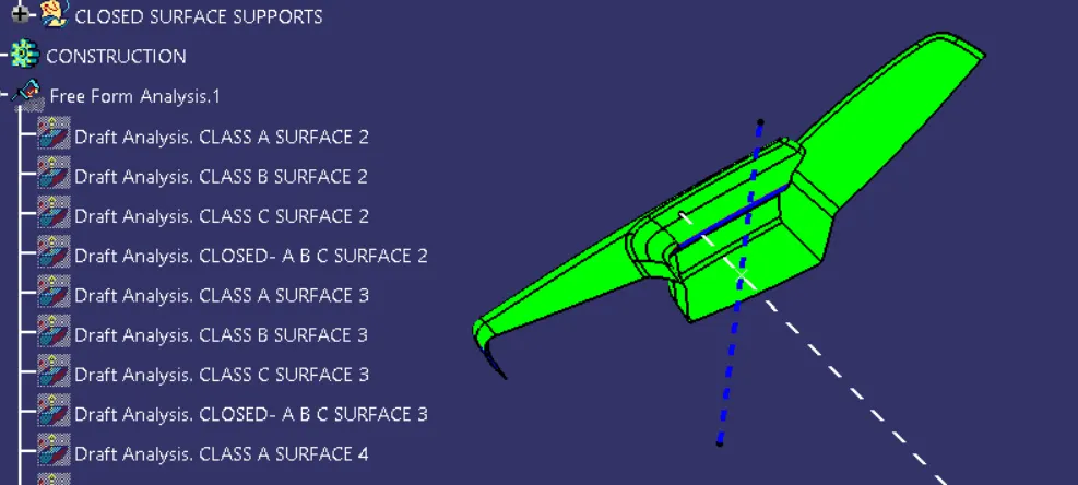
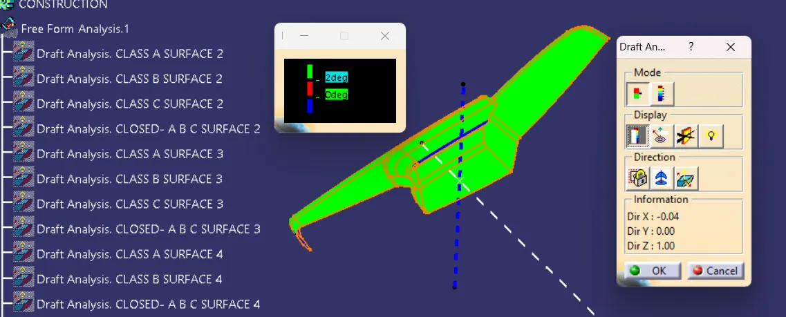
Class A surface-1 Draft analysis Class B surface-1 Draft analysis
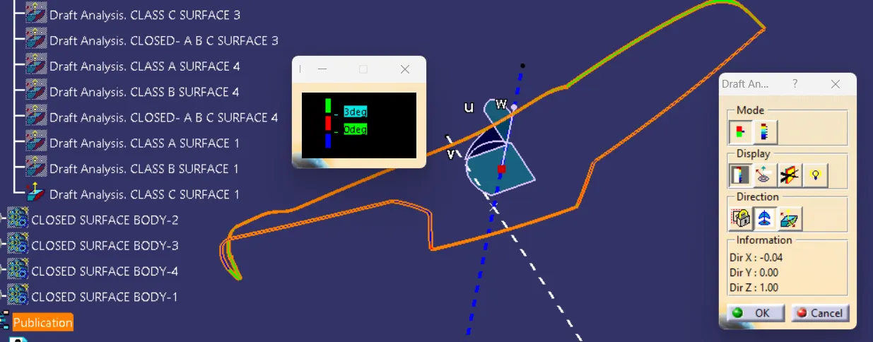
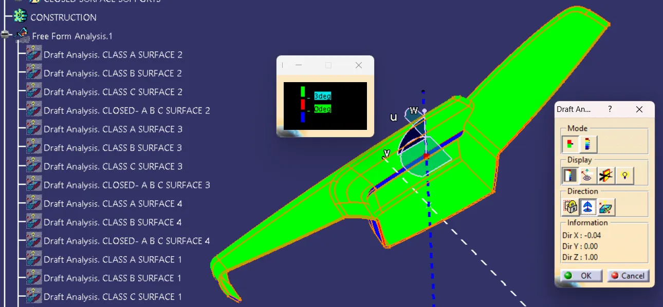
Class C surface-1 Draft analysis Closed surface-1 Draft analysis
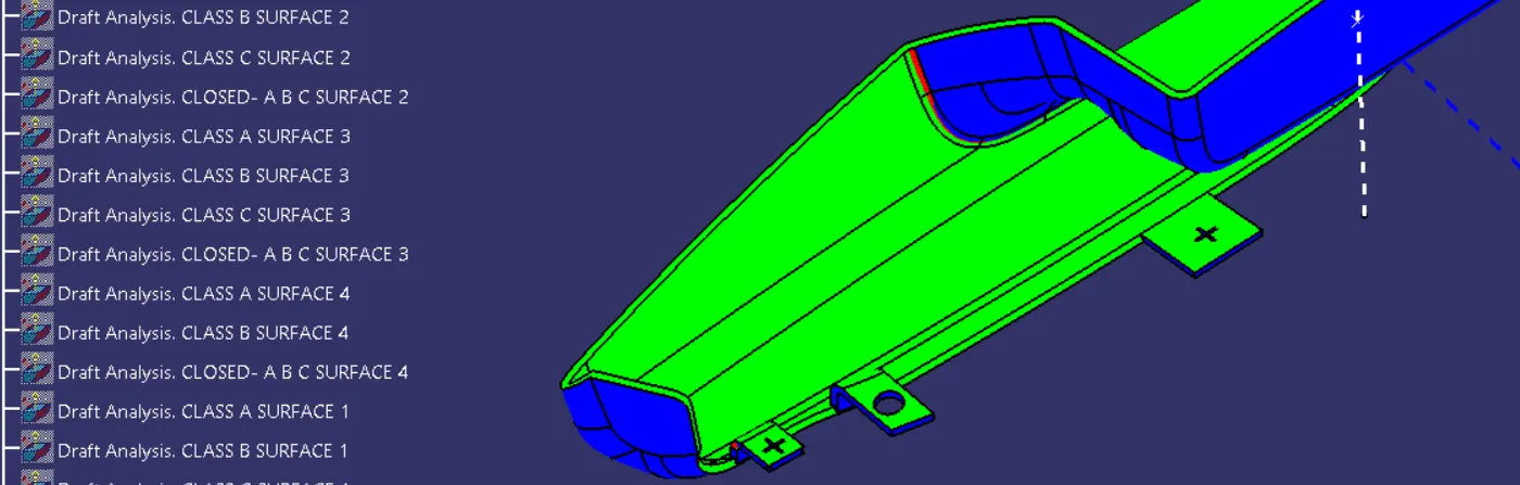
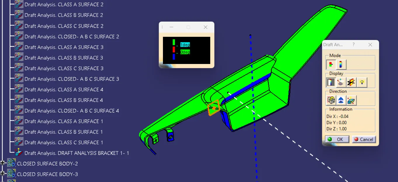
Class Bracket surface-1 Draft analysis Class Bracket surface-1 Draft analysis
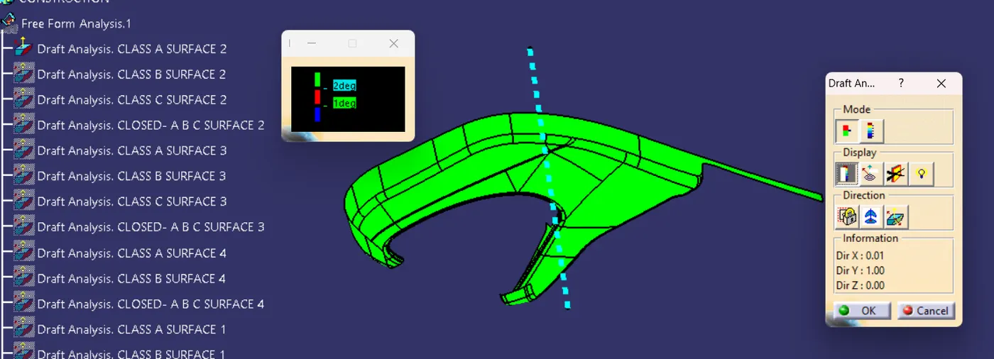
Class A surface-2 Draft analysis Class B surface-2 Draft analysis
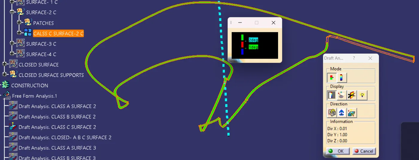
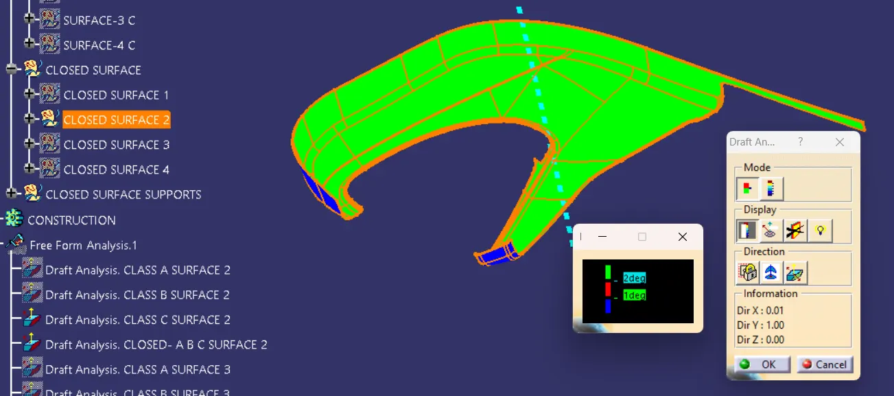
Class C surface-2 Draft analysis Closed surface-2 Draft analysis
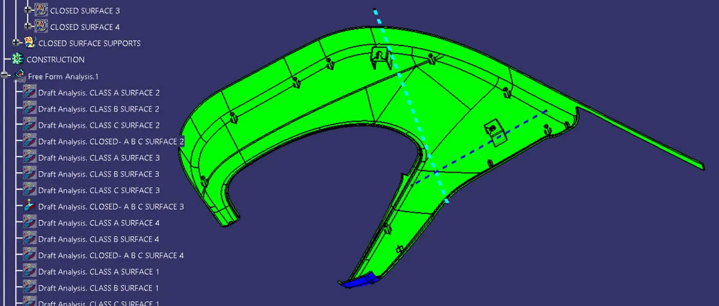
Closed surface Draft analysis
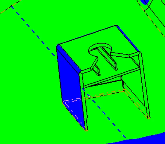
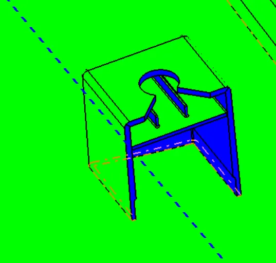
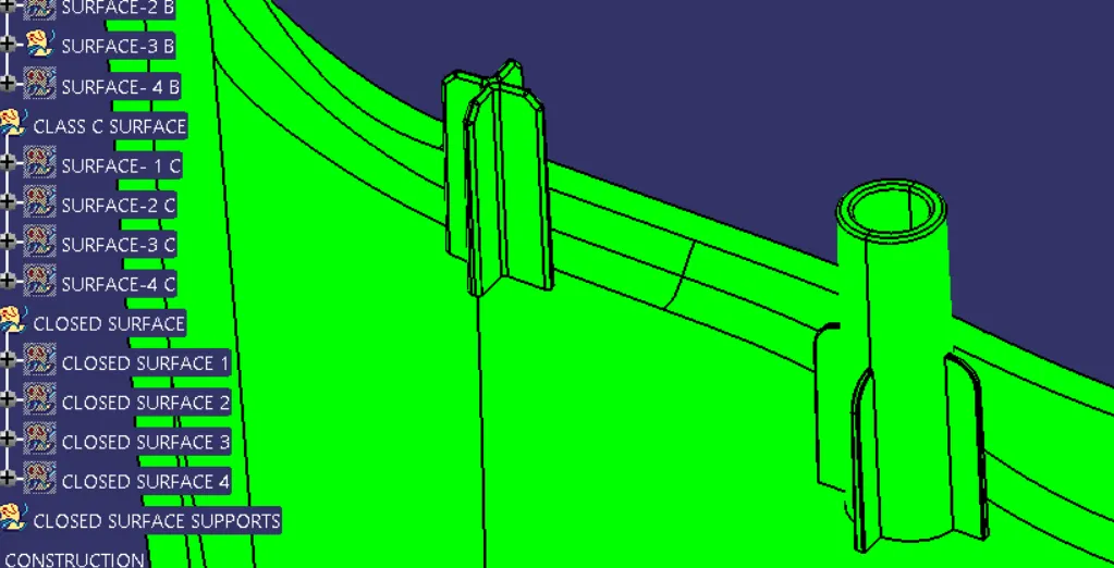
Dog House Draft analysis Rib Design
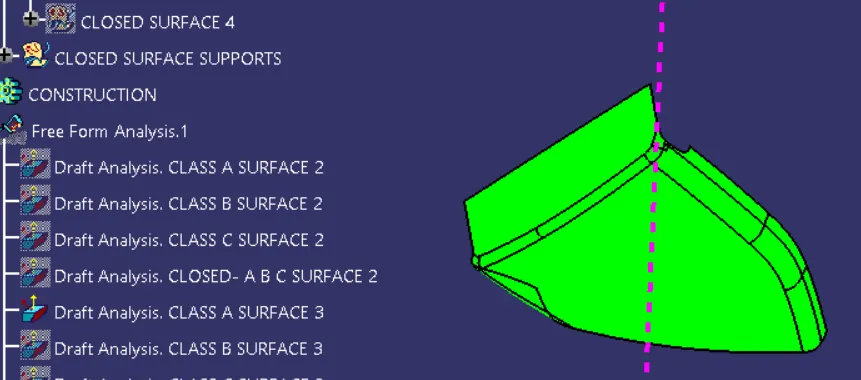
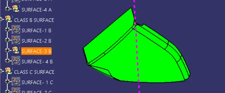
Class A surface-3 Draft analysis Class B surface-3 Draft analysis
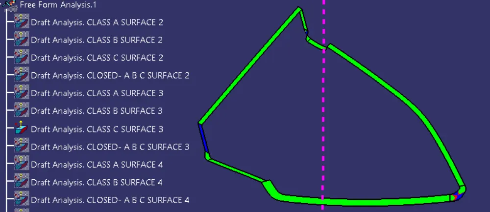
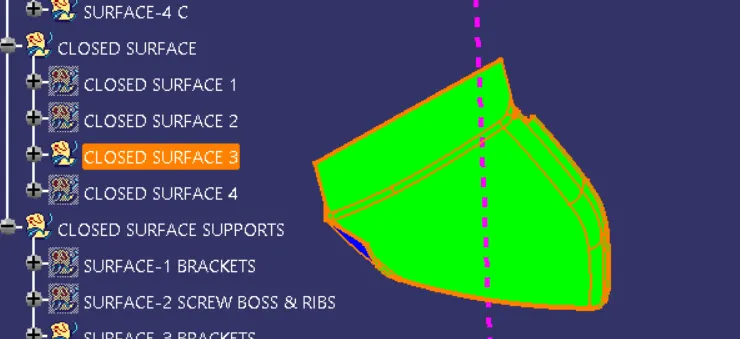
Class C surface-3 Draft analysis Closed surface-3 Draft analysis
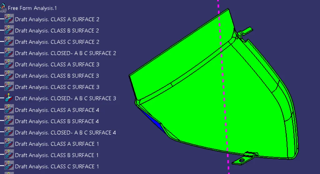
Closed surface Draft analysis
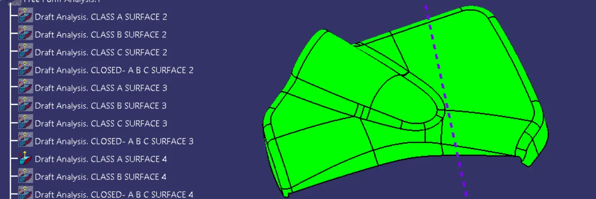
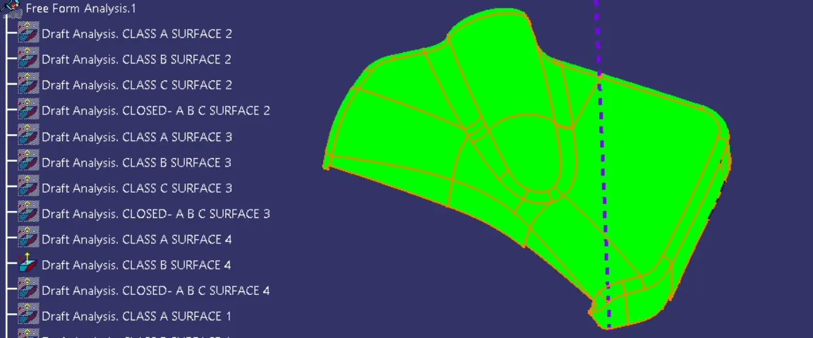
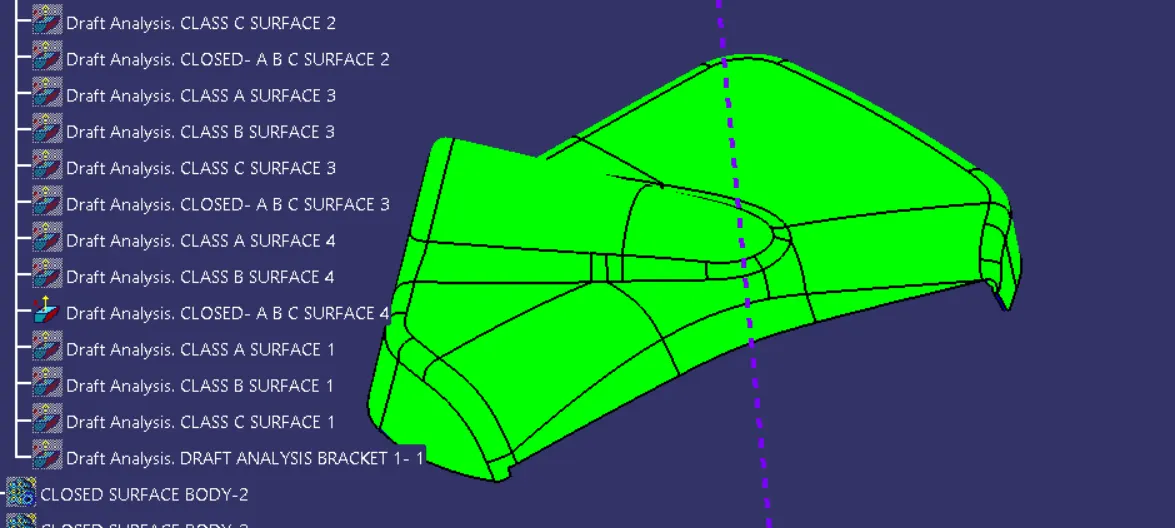 Closed surface Draft analysis
7. CLOSED SURFACE SUPPORTS
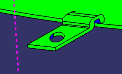
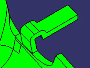
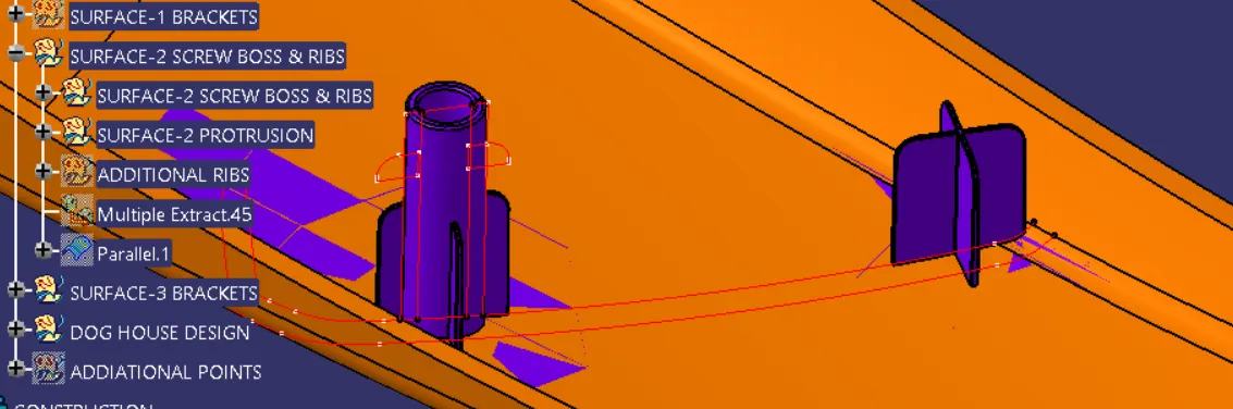
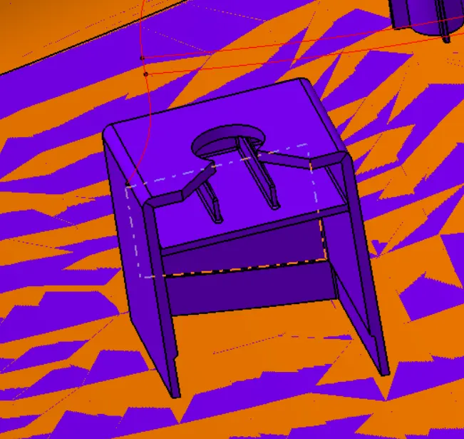
The ribs brackets are used to fixed the given components. the master section contain given ribs, bracket, dog house & masticks etc. hence for the design of given contains using master section in below pictures.
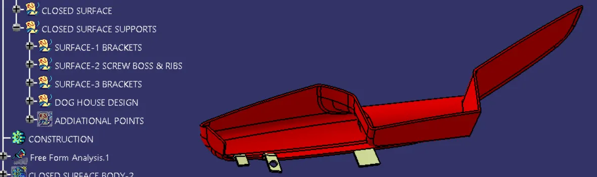
Surface-1 Brackets
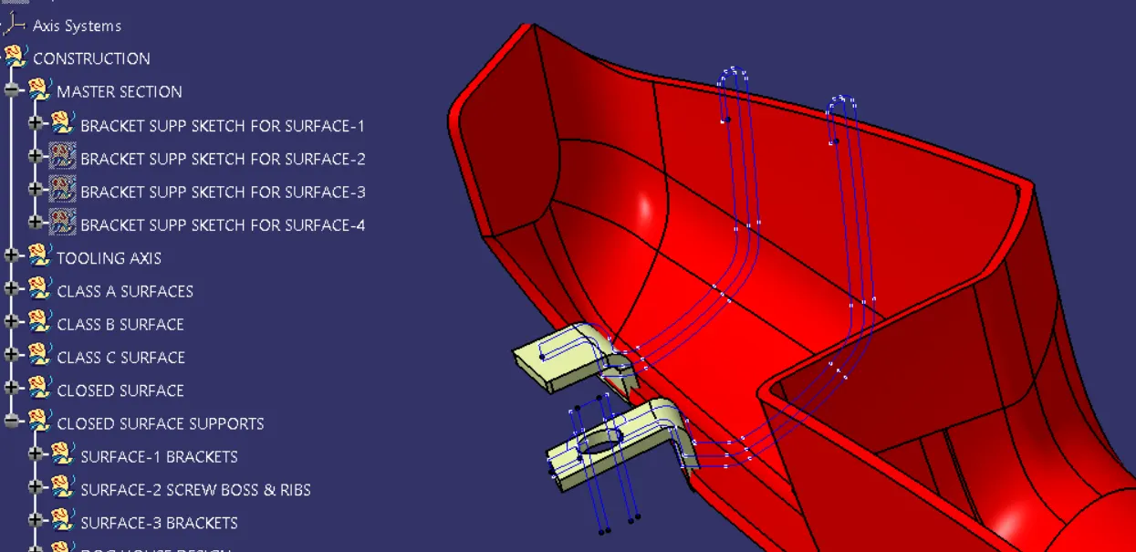
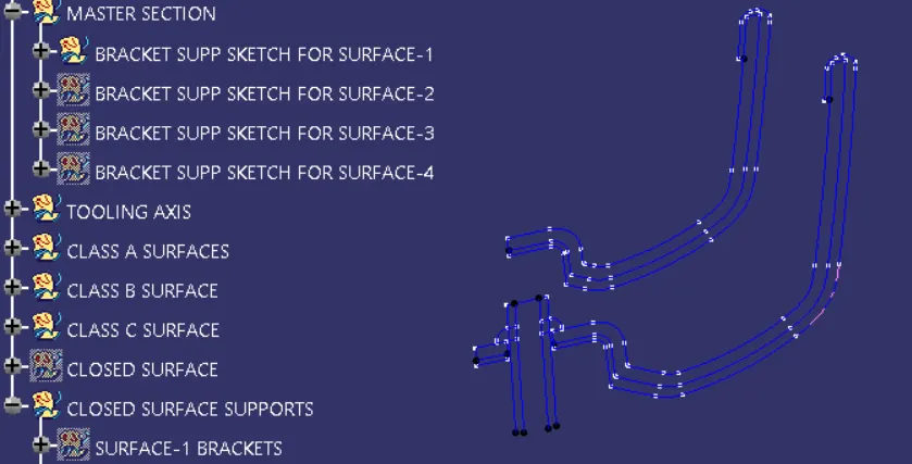
Surface-1 Brackets master section
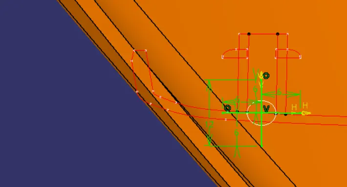
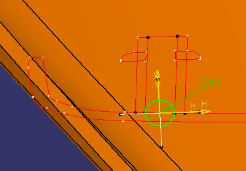
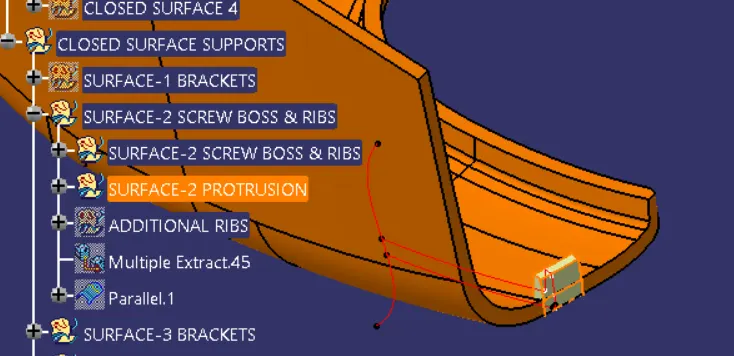
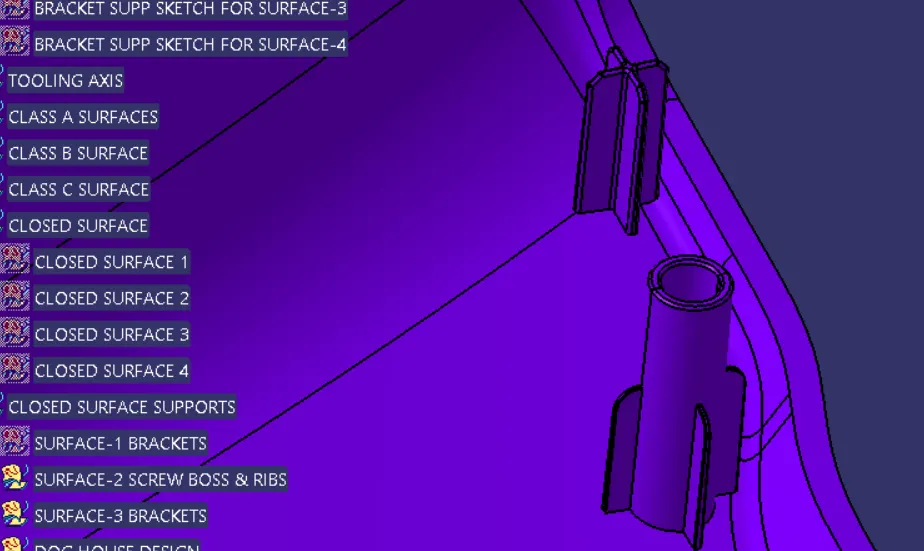
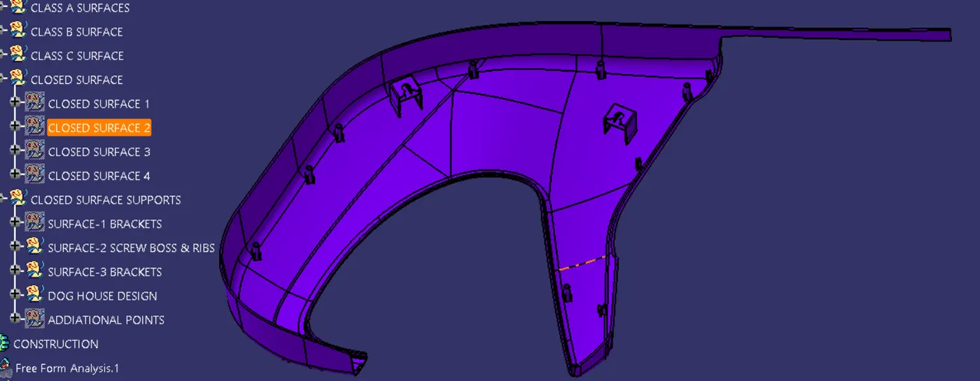
Surface-2 Brackets master section
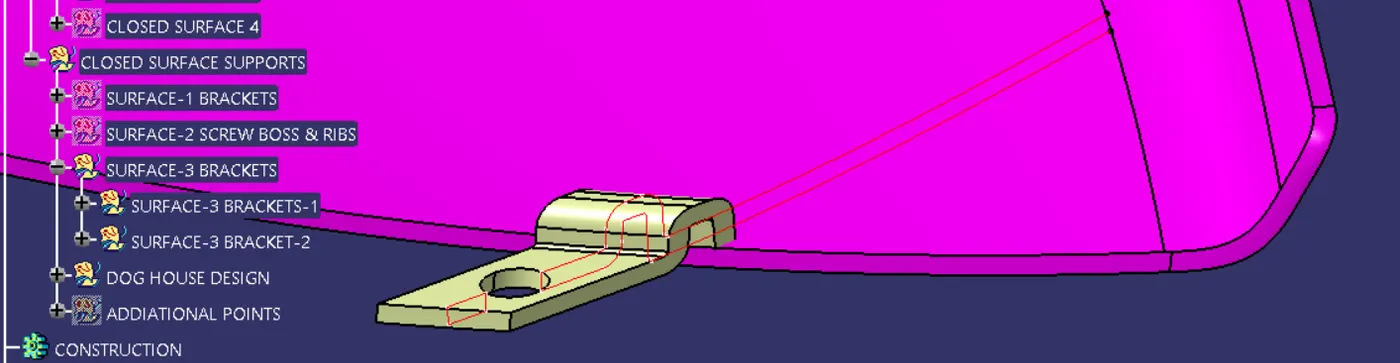
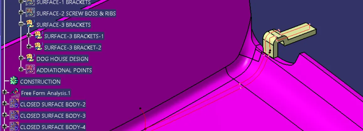
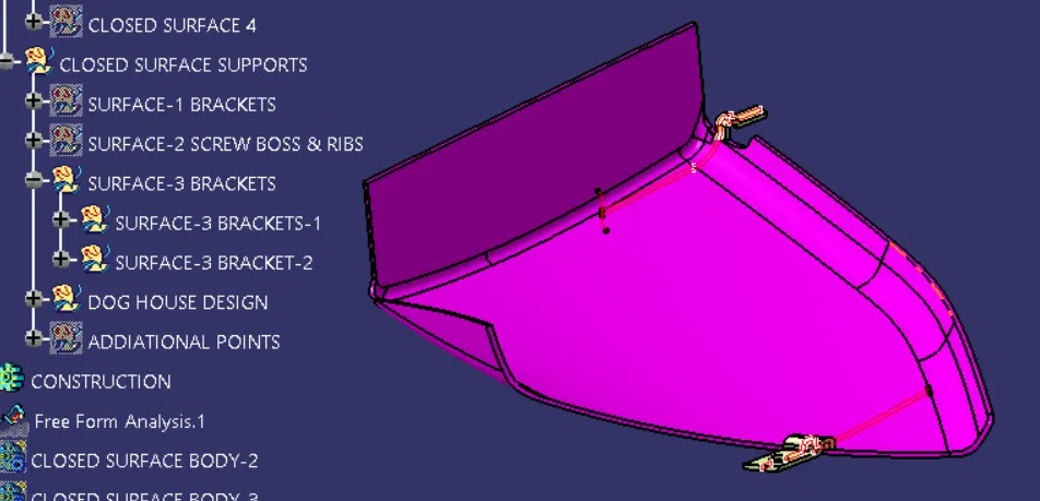
Surface-3 Brackets & master section Rib design
8. Rib & Screw Boss design.
To design rib & screw bosses consider following parameter.
| Design Rule for Rib creation in plastic design. | |||||
| Sr. No | Description | Design Rule | Parameters | Observation | Result |
| 1 | Wall Thickness (T) | It’s the thickness of component | 2.5 MM | 2.5 MM | ok |
| 2 | Rib Depth/height (H) | Rib depth=5 times the wall thickness | 5*2.5 MM | 12.5 MM | ok |
| 3 | Rib Draft angle (A) | Its 0.5 deg per side minimum | 0.5 deg | 0.5 deg | ok |
| 4 | Rib fillet/ radius (R) | Optimal radius is 0.25 MM But not violate 40% of wall thickness | 0.25 MM | 0.25 MM | ok |
| 5 | Rib thickness (W) | Its W=0.4 times the wall thickness (=40%*wall thkness) | 2.5*0.4 | 1 MM | ok |
| 6 | Rib root thickness | Its shoud not crossed 30% more, = 2.5+30%=3.25 mm | 3.25 MM | 2.686 MM | ok |
| 7 | Thickess at top | Minimum thickness at tip is 0.75 MM | 0.75 MM | 0.75 MM | ok |
| Design Rule for screw boss creation in plastic design. | |||||
| Sr. No | Description | Design Rule | Parameters | Observation | Result |
| 1 | Wall Thickness (T) | It’s the thickness of component | 2.5 MM | 2.5 MM | ok |
| 2 | Screw boss Thickness (T) | Tipically 40% of nominal wall thickness | 2.5*40% | 1 MM | ok |
| 3 | Screw boss Depth/height (H) | Screw boss depth=5 times the wall thickness | 5*2.5 MM | 12.5 MM | ok |
| 4 | Screw boss Draft angle (A) | Its 0.5 deg for minimal wall thickness at inside & outside respectively | 0.5 deg | 0.5 deg | ok |
| 5 | Screw boss fillet/ radius (R) | Optimal radius is 0.25 MM But not violate 40% of wall thickness | 0.25 MM | 0.25 MM | ok |
| 6 | Screw boss side wall thickness (W) | Its W=0.6 times the wall thickness | 2.5*0.6 | 1.5 MM | ok |
| 7 | Screw boss root thickness | Its shoud not crossed 30% more, = 2.5+30%=3.25 mm | 3.25 MM | 2.686 MM | ok |
| 8 | Thickess at top | It shout be 0.75 mm. (Its not maximum or minimal select intermidate) | 0.75 MM | 0.75 MM | ok |
9. Dog house design
Dog houses are designed to avoid SINK MARK created on the CLASS-A surface by screw bosses and to solve the length issues when giving screw bosses which need to be assembled to other components. It is also useful when perpendicular screw bosses are required on the part to the tooling direction.
C thickness should be 40% of the main wall thickness T
Minimum width of the dog house is 12 mm.
Height of B should be 3-6 mm
- Minimum draft for the do house degrees 5 degrees to die draw.
- irection.
-
- Dog house design
10. Given master section flanges and brackets design
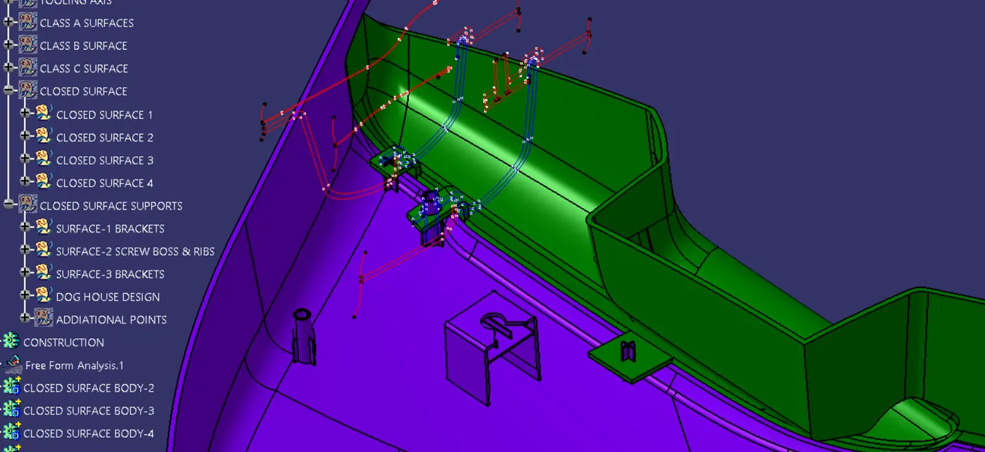
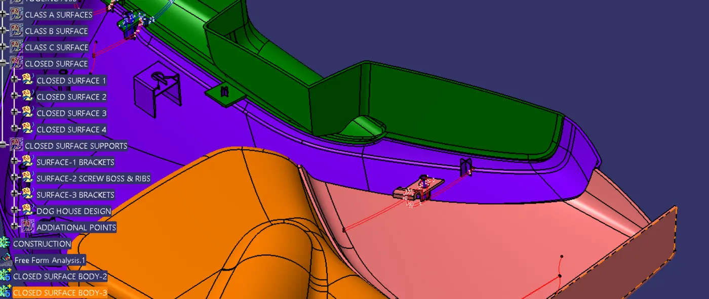
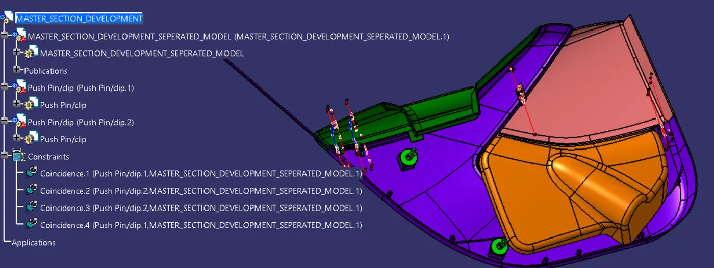
11. Bush assembly
12. Result & conclusion
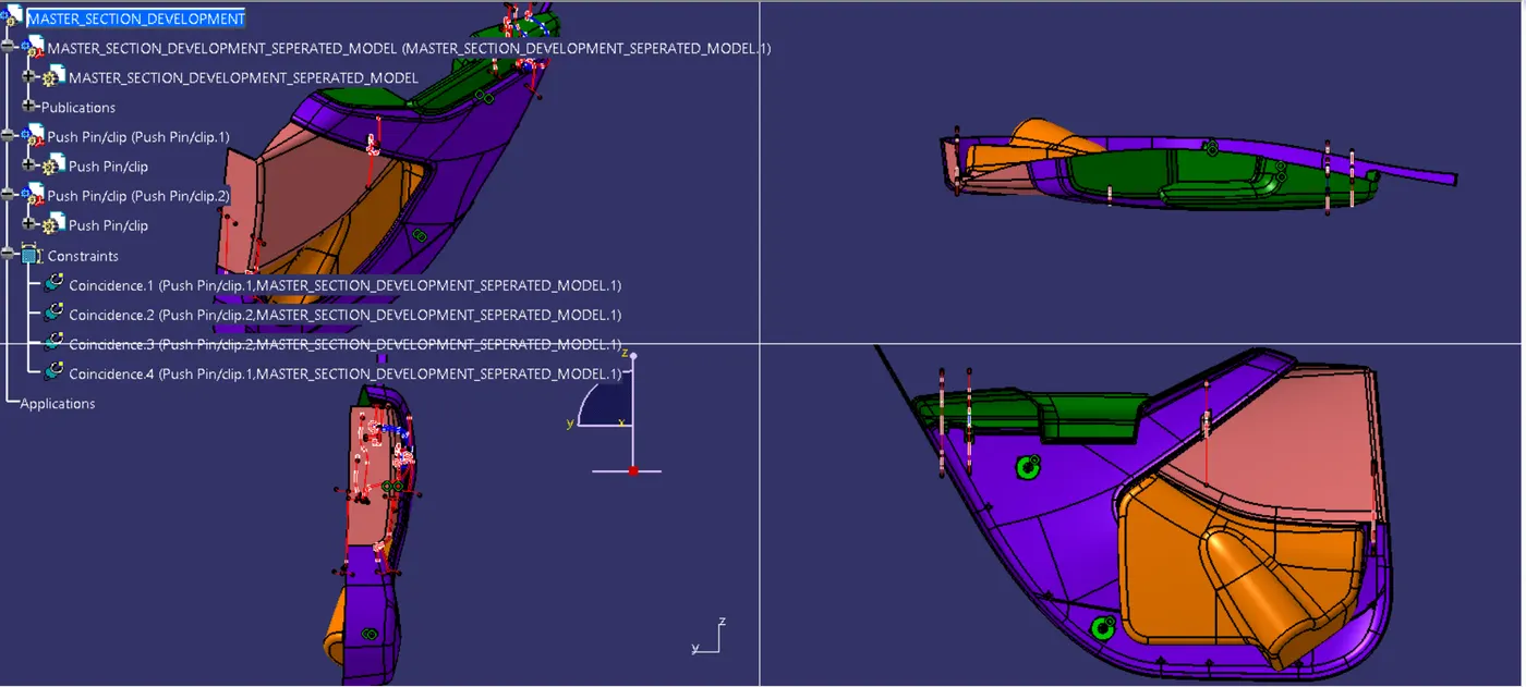
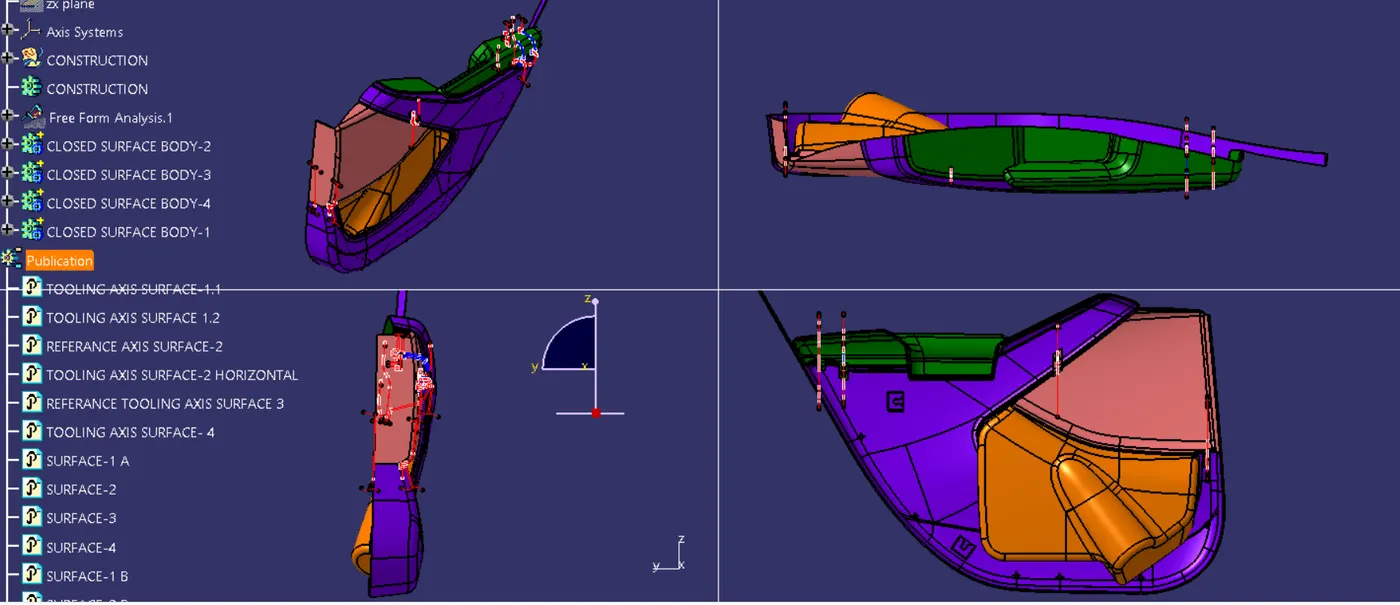
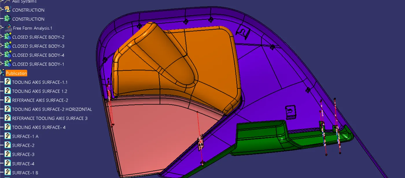
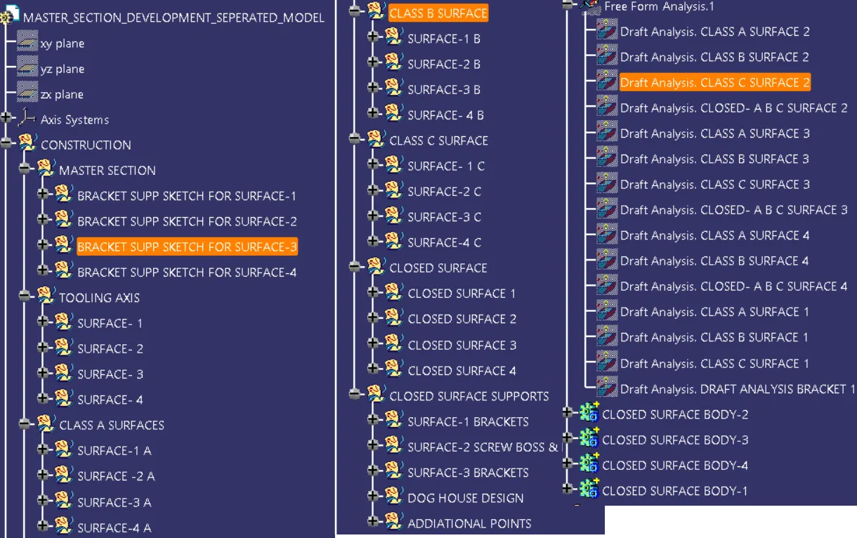
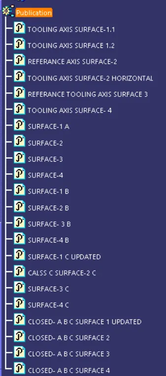
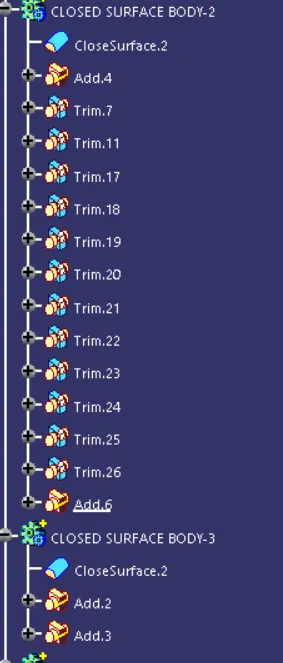
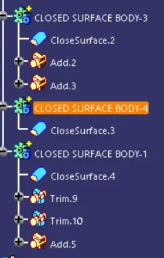
Tree Diagram.
In this way we have successfully completed the given challenges.