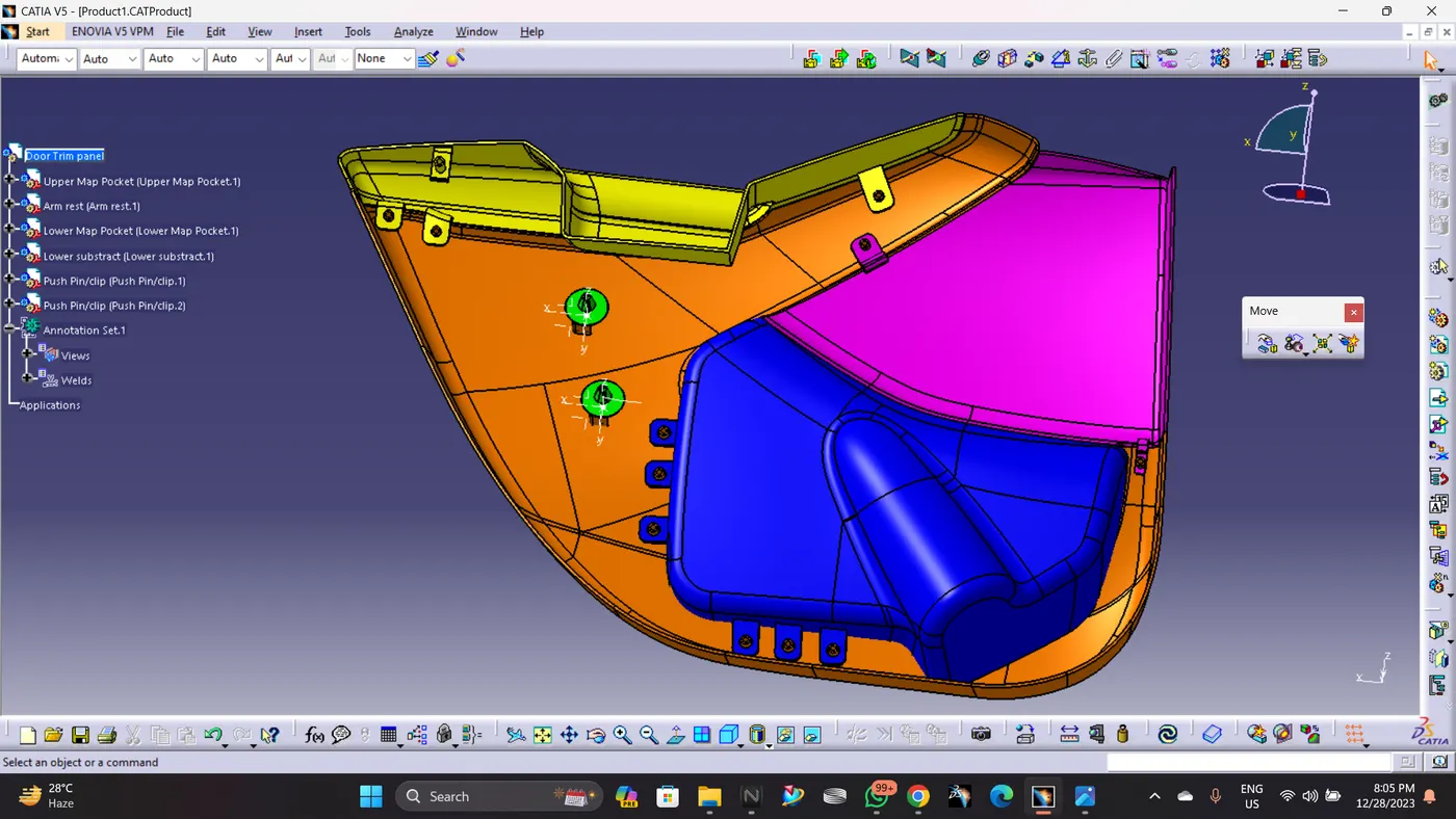
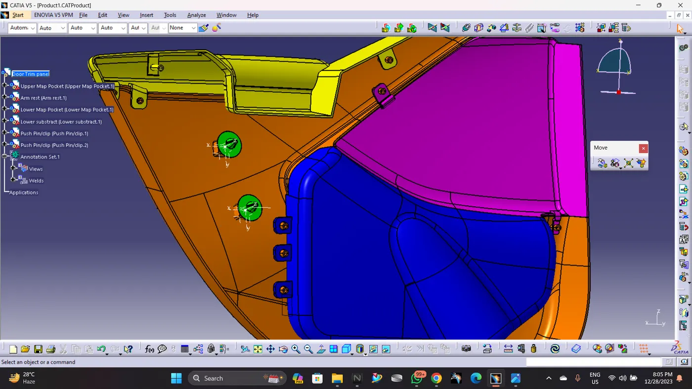
Week 12- Final project
Final project
DOOR TRIM PANEL
AIM - Creation of CAD model considering following inputs as like in OEM and tier1 companies.
Door trim panel is creation of CAD model considering following inputs as like in OEM and tier1 companies
Class A surface is givin but after applying boundries check, it has been found there is some improvement needed to be actioned to get a closed surface. Nominal thickness is taken from the provided master sections.
Based on the knowledge that has been gained by taking the Plastic Design Course by CATIA V5 I have develped Class B Surgaces, Class C Surfaces, tooling axis for every single part, also, I found a strategy to assemble the four seperate parts into one part design by creating engineering features such as Heat Stakes, Ribs, Dog Houses and Flanges.
STEP 1. CHECKING CONTINUITY OF GIVEN CLASS-A.
A) ARM REST
Class A Improved:
Given Surface
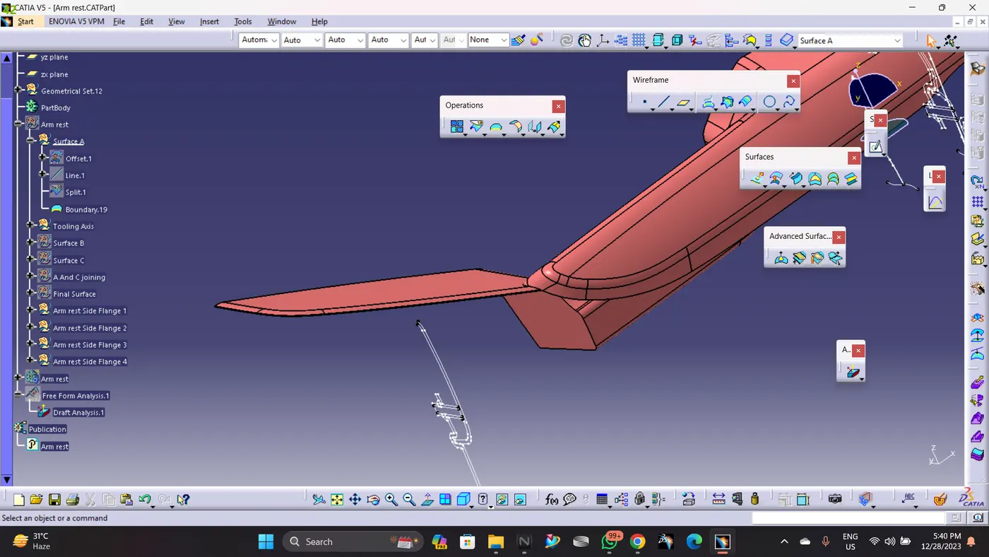
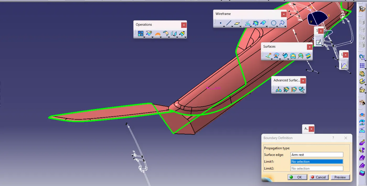
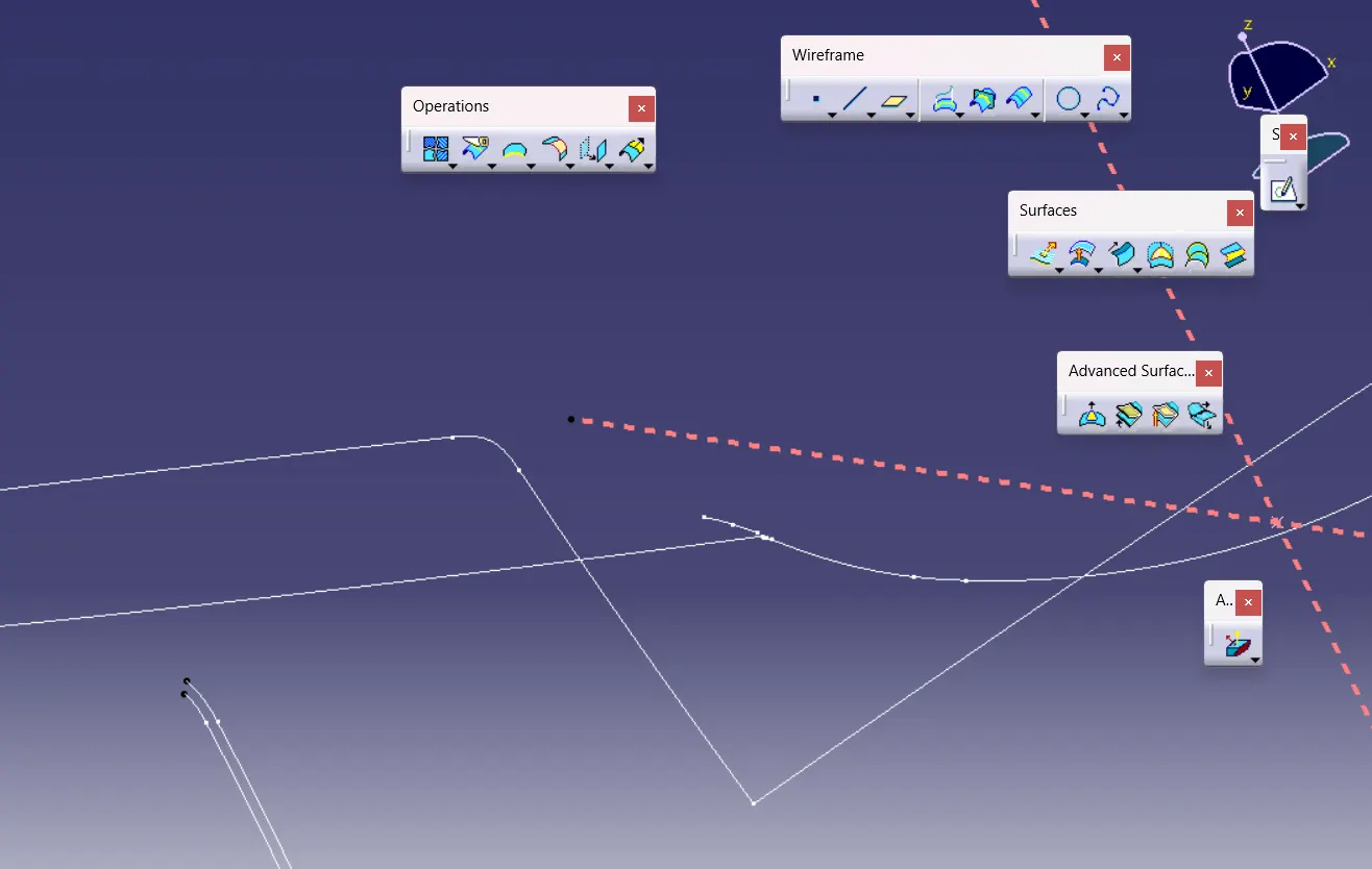
AS THERE IS DISCONTINUITY IN THE GIVEN CLASS-A,THATSWHY IT IS SHOWING TWO DOMAINS OF CURVE AFTER DISASSEMBLING THE BOUNDARY.
Final A Surface
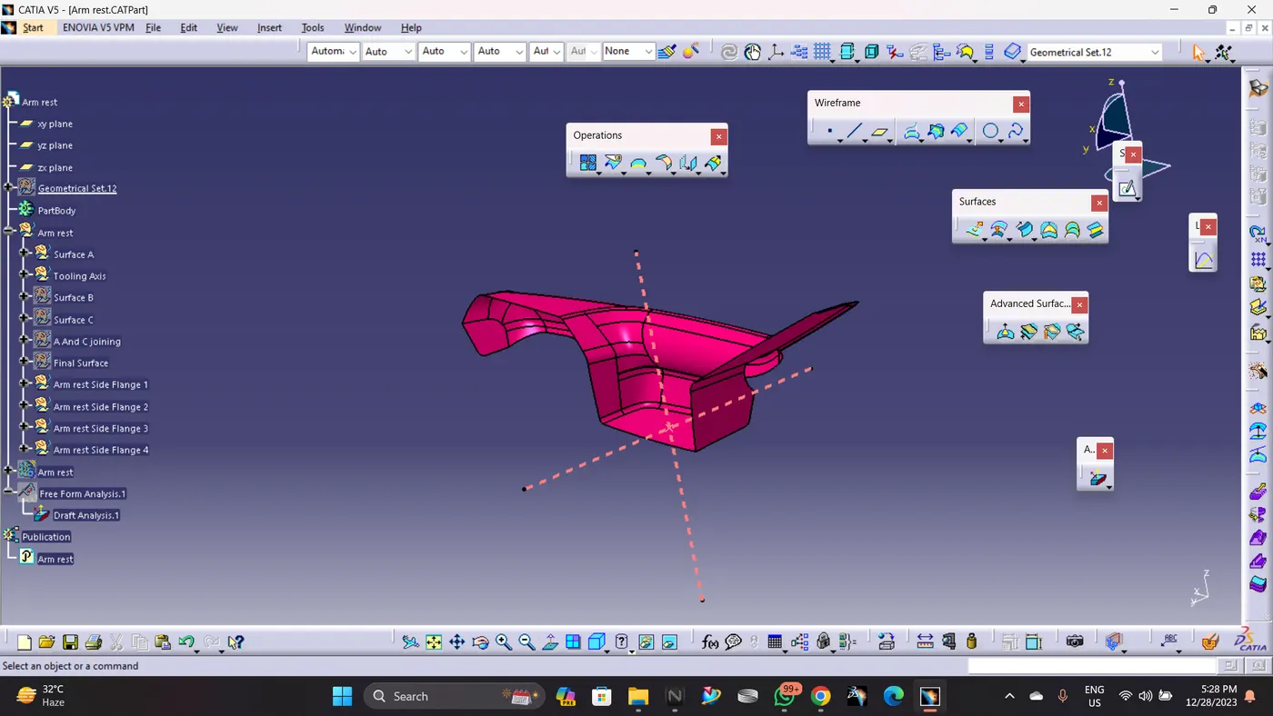
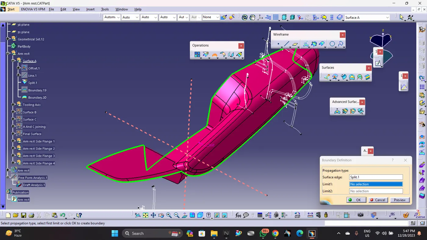
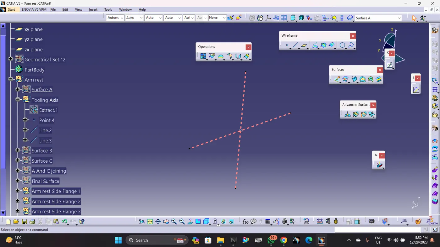
Main Tooling Axis and Side Tooling Axis are created in such way to provide drafting.
Creation of class B surface:
Class B is created by offseting Improved Class A by 2.5 mm as per the master section.
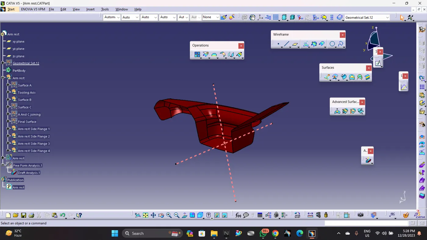
Creation of class C surface :
Class C is created by sweeping Improved Class A Surface and it has been trimed with Class B Surface.
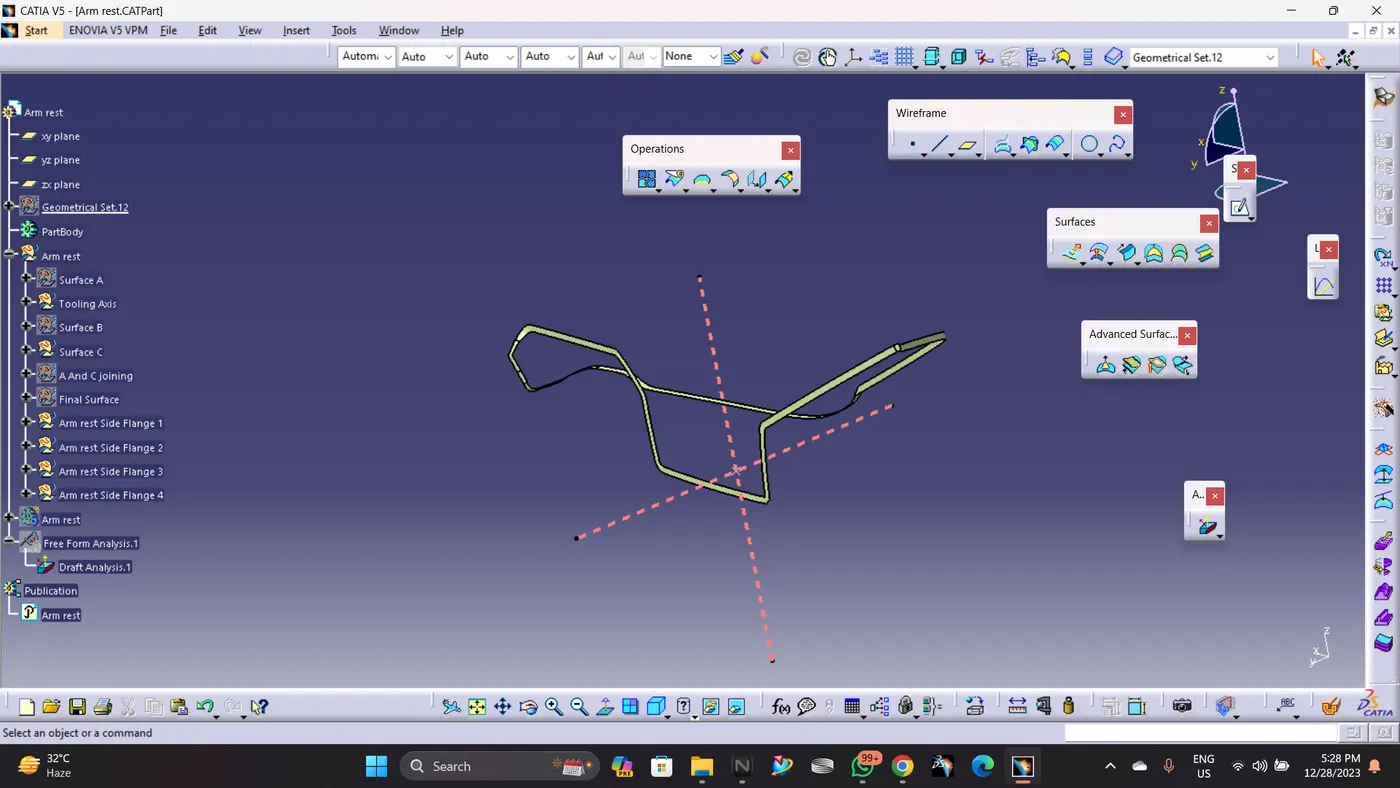
Class A and Class C Joining
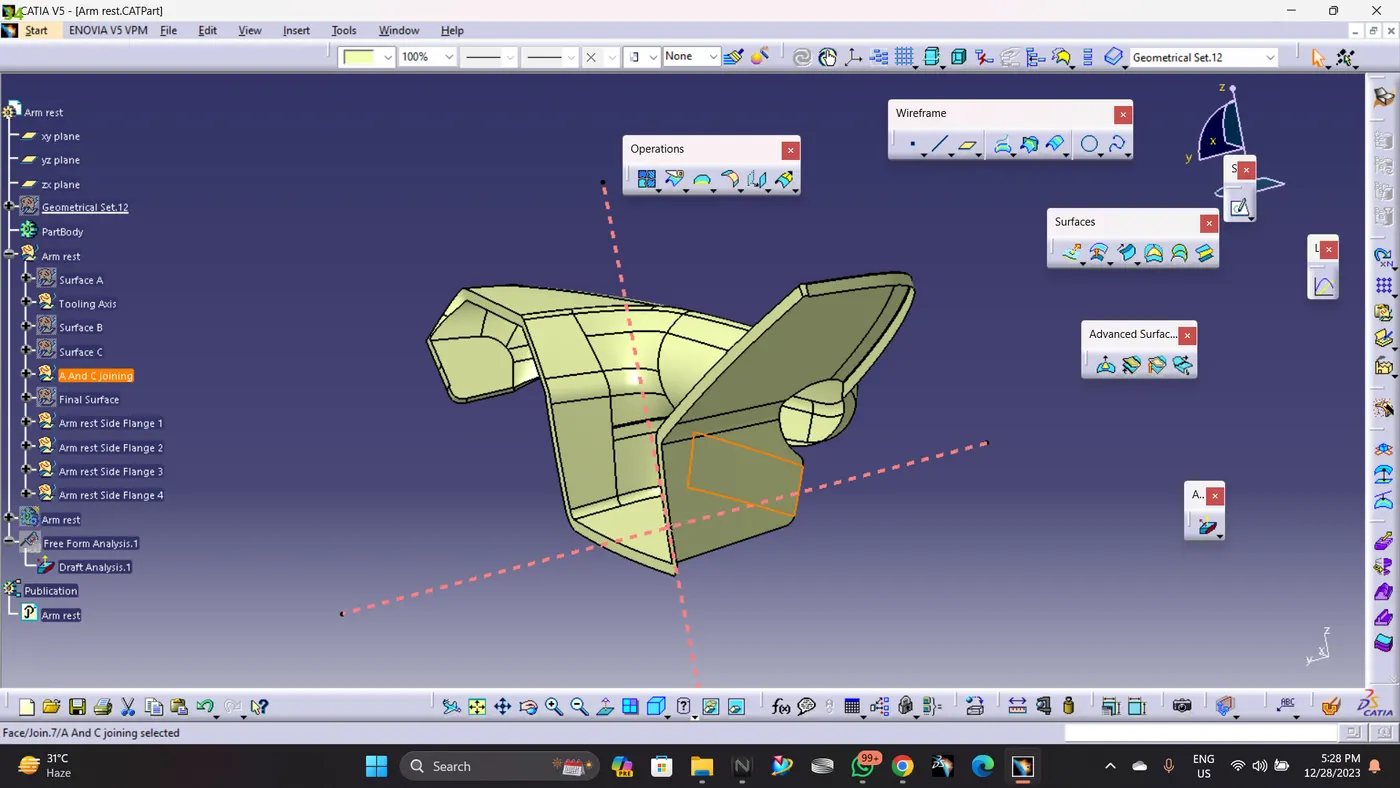
Class A,B And C Joining
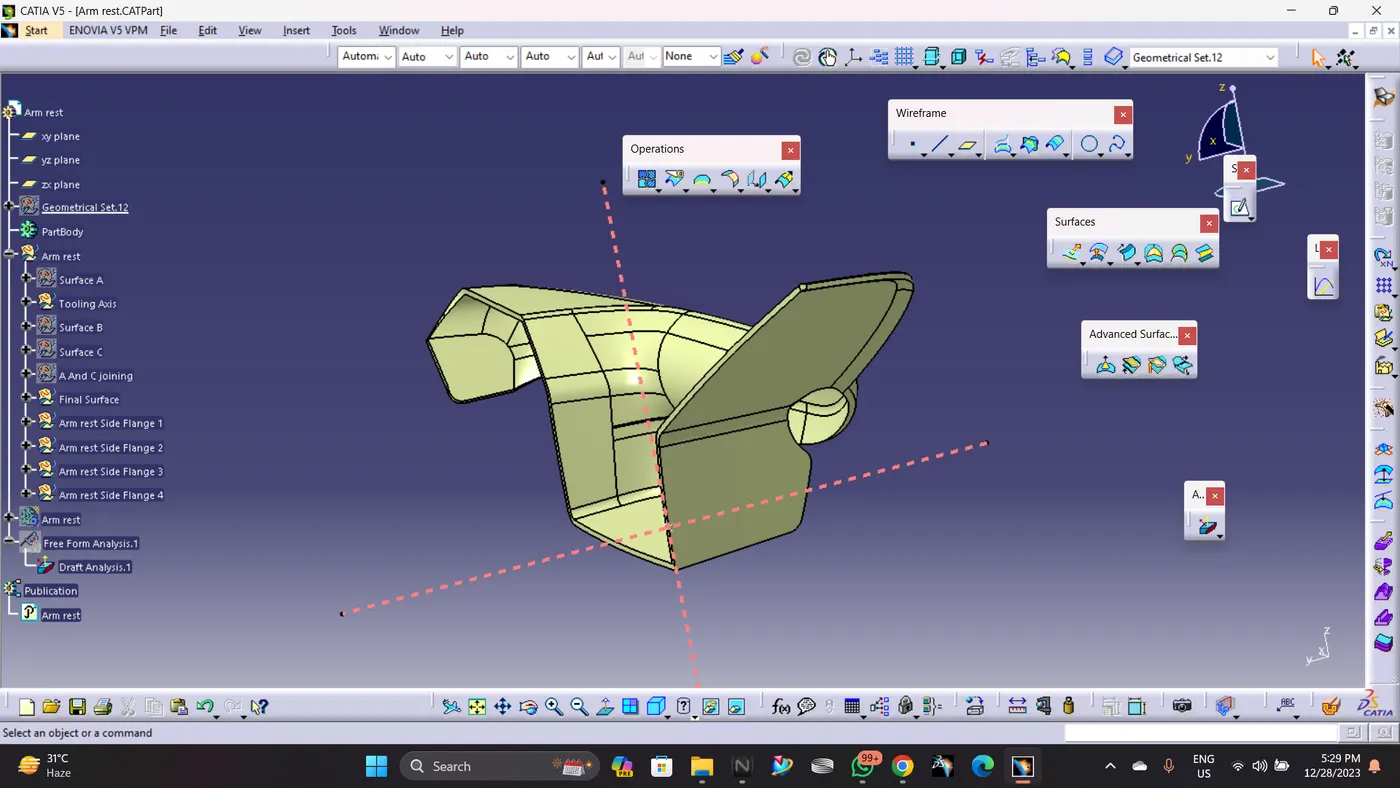
Closed Body
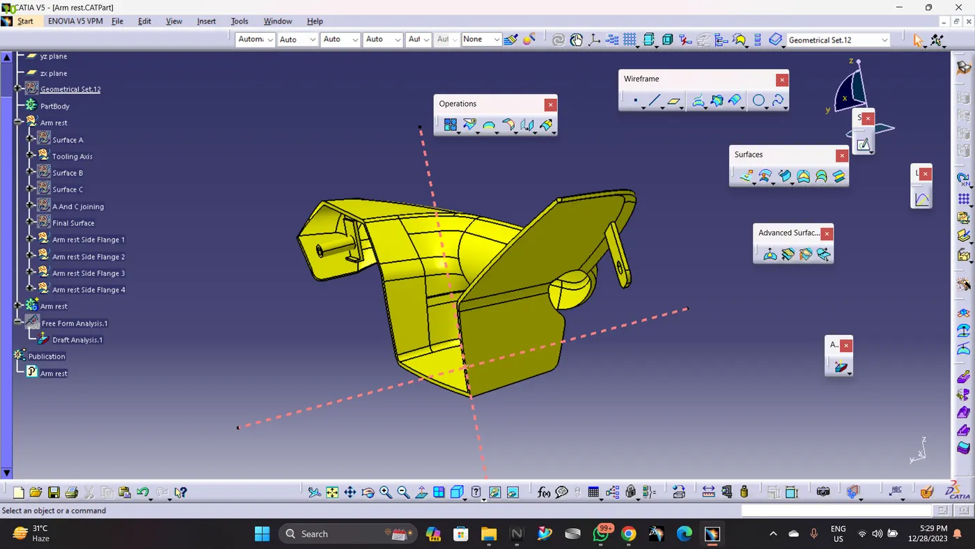
Creating flage on Arm Rest
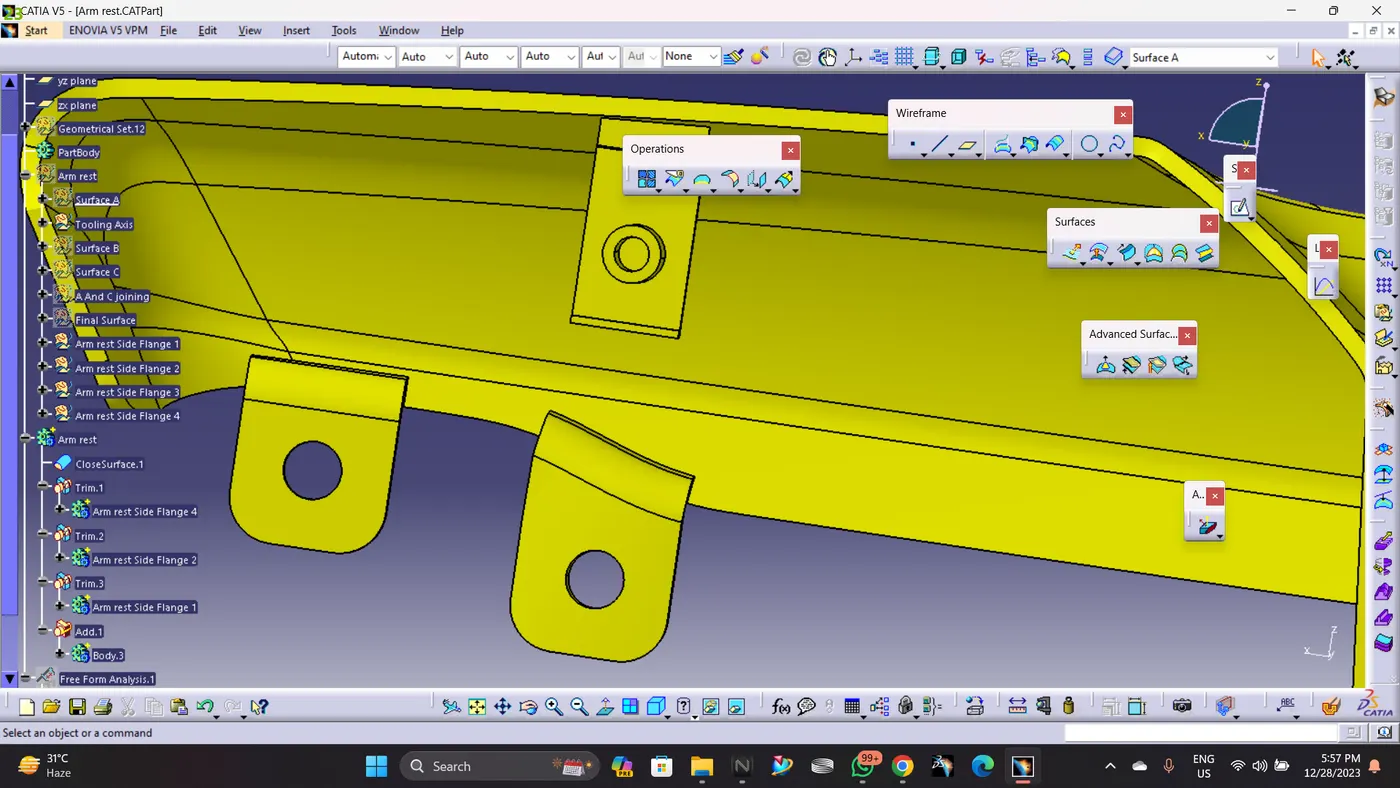
In oder to Join the Armrest body with the other bodies, I created 4 Flanges seperatly with counter holes, Flanges are different based on the engineering features will be held. Then these flanges are assembled to the main body (Armrest) by unitrim feature.
Each Flange was created by extracting surface from Class C Surface aidded by Generative Surface. then I applied close surface feature to creat the flange body, Drafted by 0.5 deg, Filletted. Also it is important to mention that the counter holes were created by iso constrained, positioned sketches and then paded it and drafted before it was removed from the main flange.
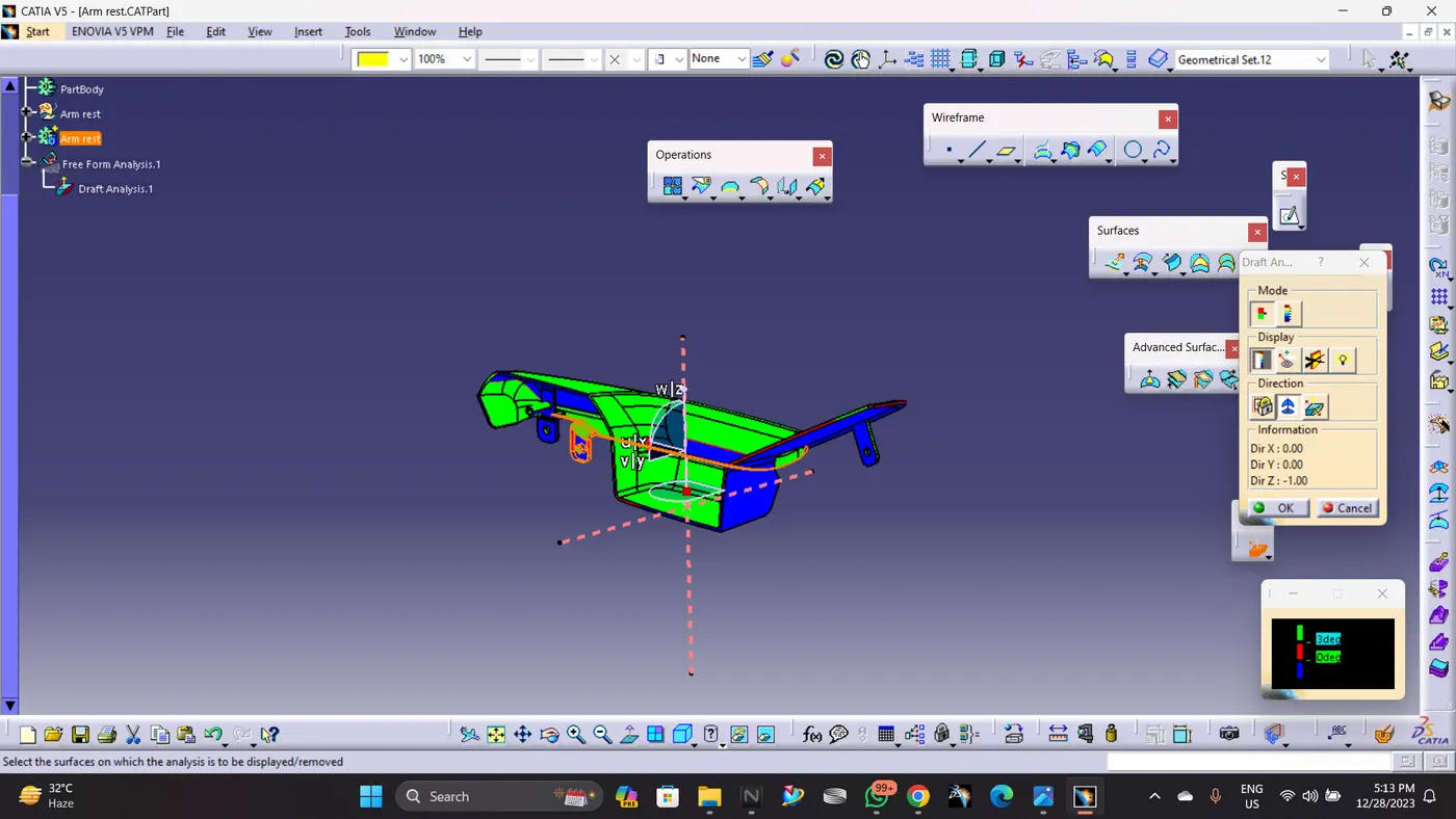
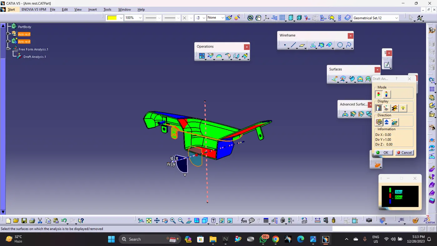
Drafting Analysis:
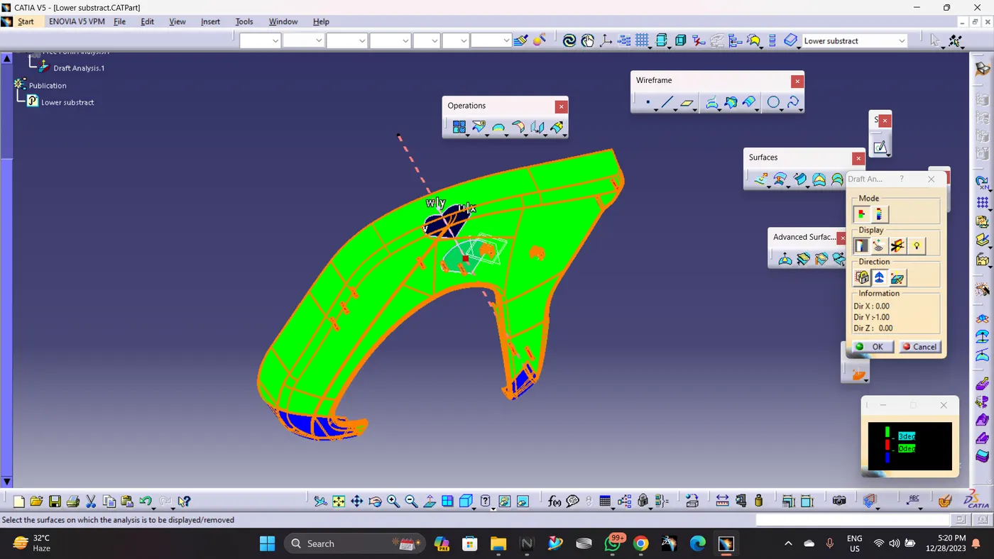
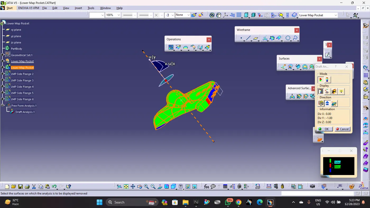
By applying drafting analysis at 3 Deg, we can see must bodies are been cleared. As Green set at 3 degree, blues is Zero and less than Zero it is red colored.
B) Lower substract:
In case of the door lower substract after examining the provided input surface we can able to detect a projection or an extension so we don’t need it for any further so, create a line and split the unnecessary surface
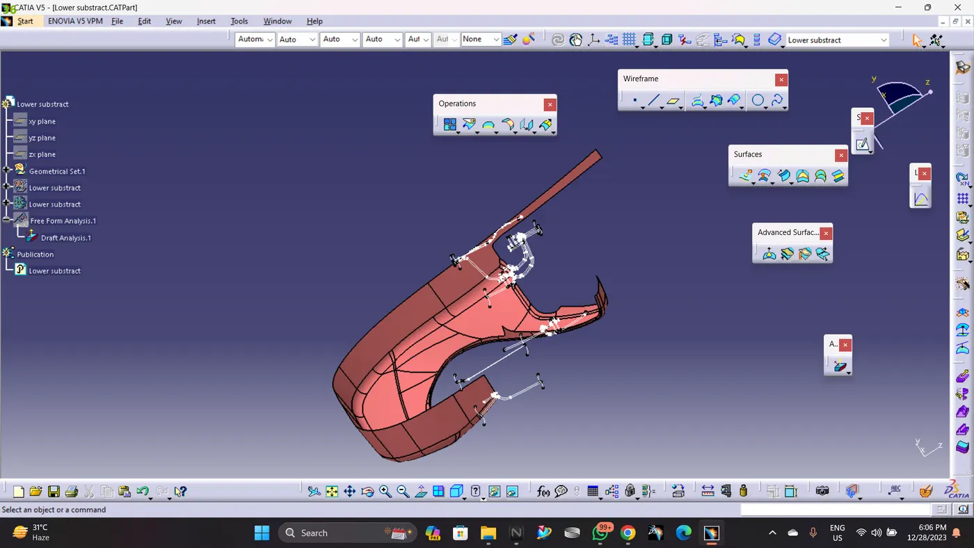
So my class A surface is ready
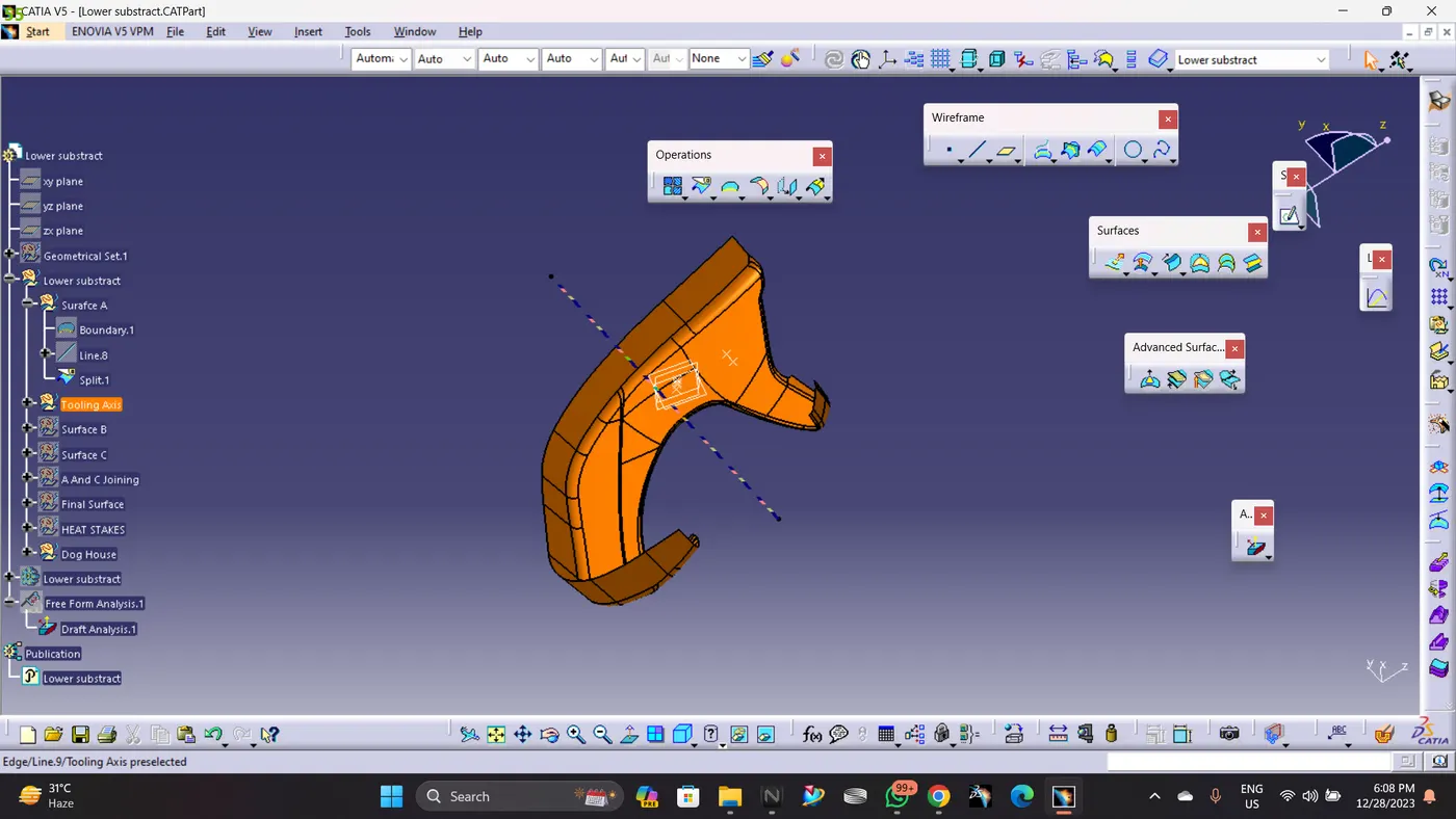
Tooling axis creation:
Extract the surface from the class A where the surface is entirely visible and easy for the manufacturing by viewing the surface in different orientations
Now create a point at the middle At 0 coordinates and create a line in point and direction method and the create line is our main tooling axis
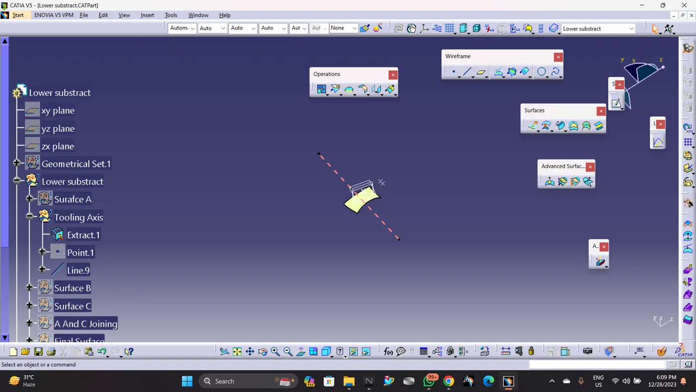
Creation of class B surface:
lower substract offset the class A surface to a value of 2.5 mm beneath the class A surface then extrapolate the class B surface which would help to make the final trim
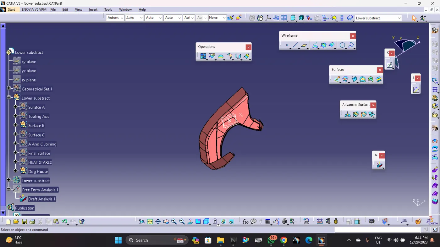
Creation of class C surface :
Class C is created by sweeping Improved Class A Surface and it has been trimed with Class B Surface.
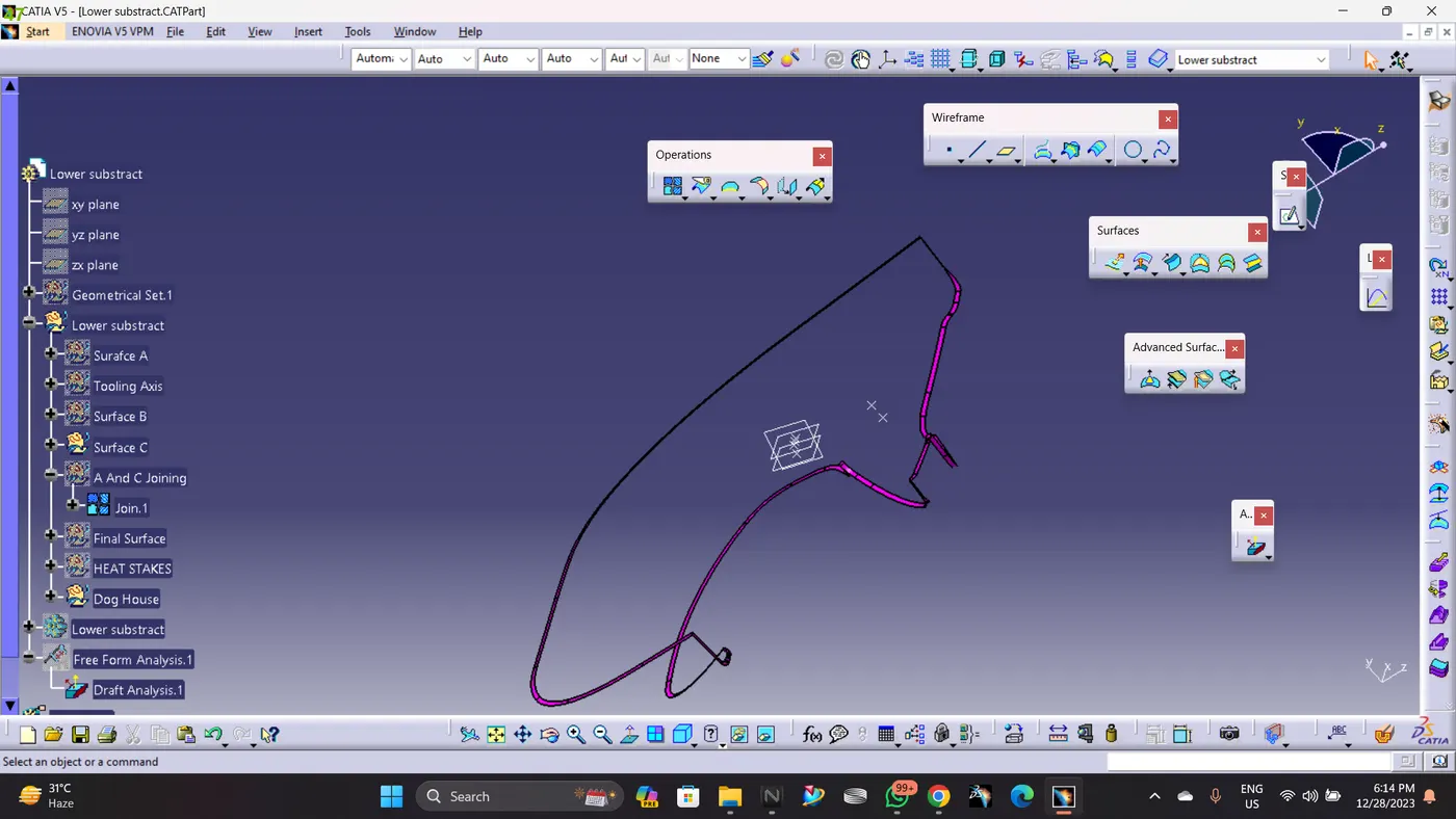
Class A and Class C Joining
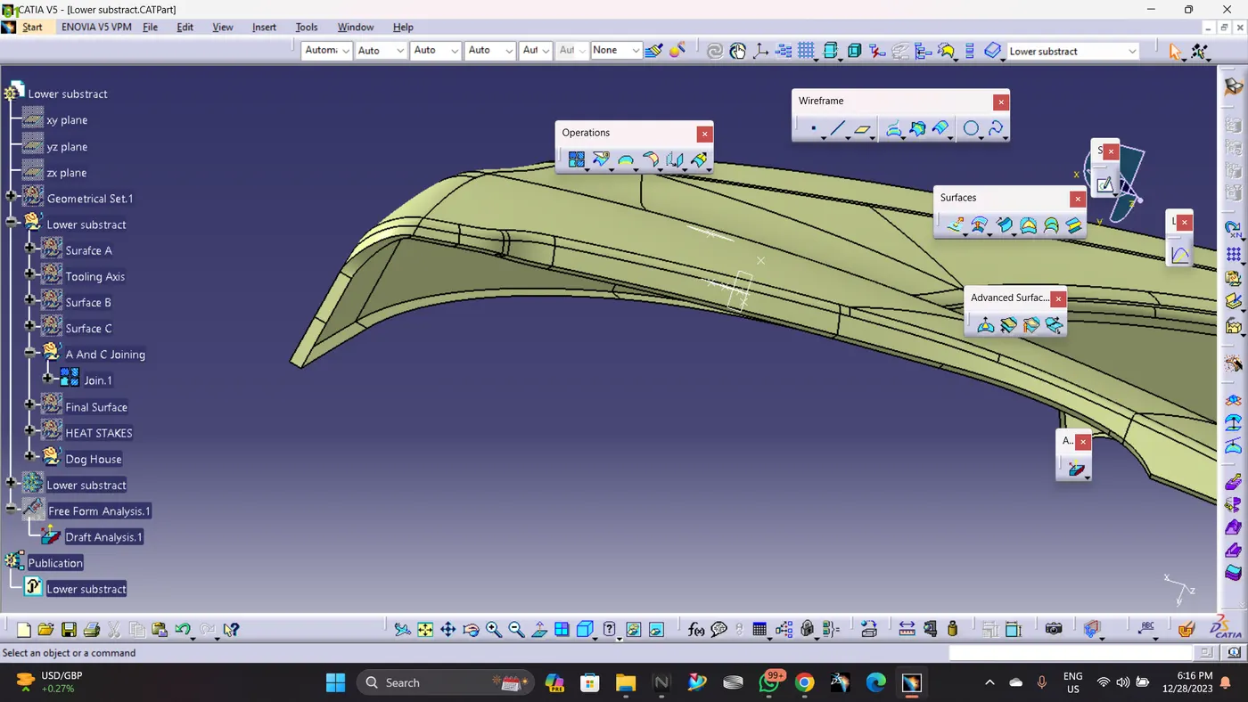
Class A,B And C Joining
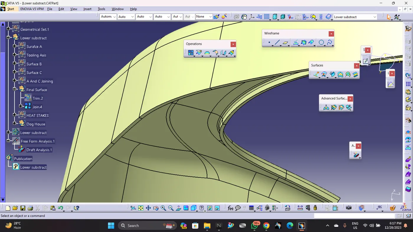
Creating Heat stakes And Dog House
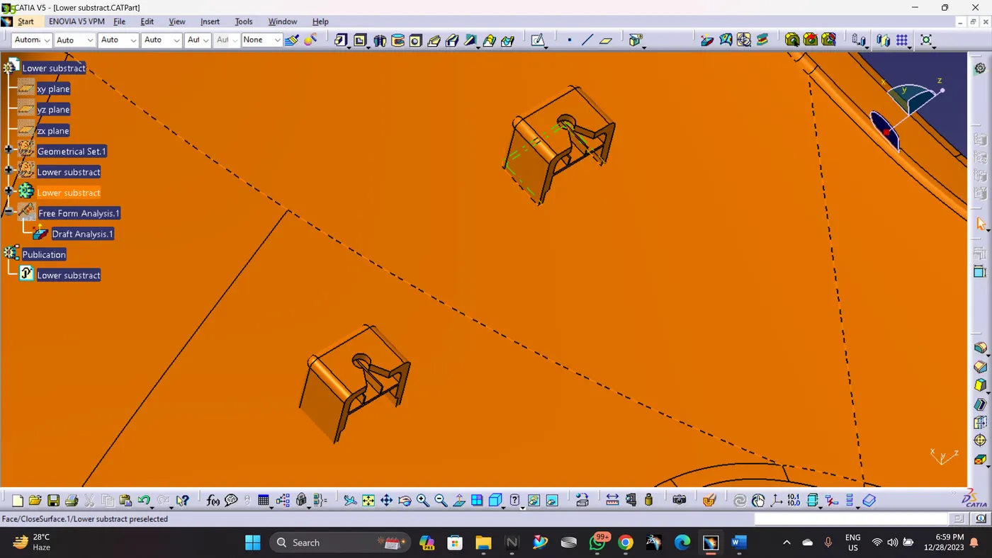
In oder to Join the Lower Sustrate with the other bodies, I will be useing the Lower Subtsrate as the main body where other can be installed accoring to it. All connecting engineering features are created attched to this body while flanges will be conecting this main body to other bodies. 2 dog houses are created, 11 heat stakes
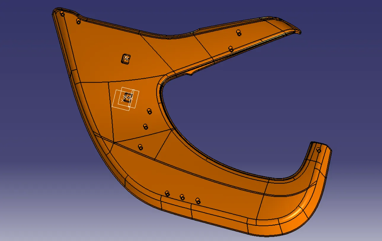
Drafting Analysis:
C) Upper Map Pocket:
Class A
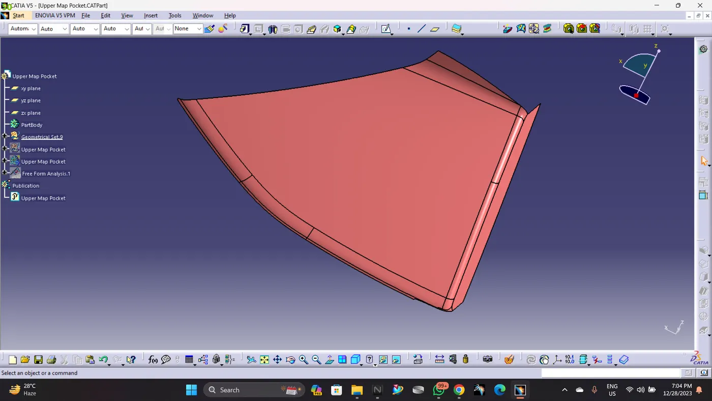
A- Class A Surface was givin is checked and found out it is perfectly closed boundries,no further action to be taken.
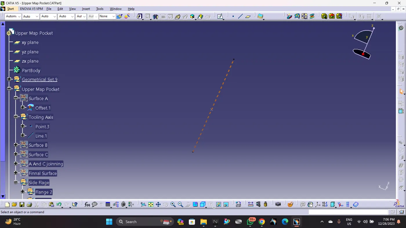
Tooling axis creation:
Creation of class B surface:
Class B is created by offseting Improved Class A by 2.5 mm as per the master section.
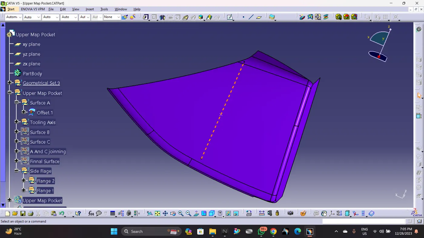
Creation of class C surface :
Class C is created by sweeping Improved Class A Surface and it has been trimed with Class B Surface.
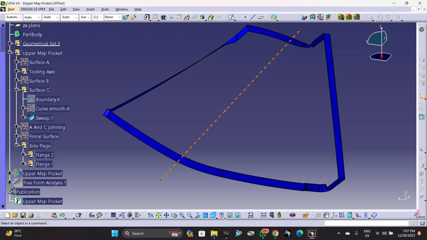
Class A and Class C Joining :
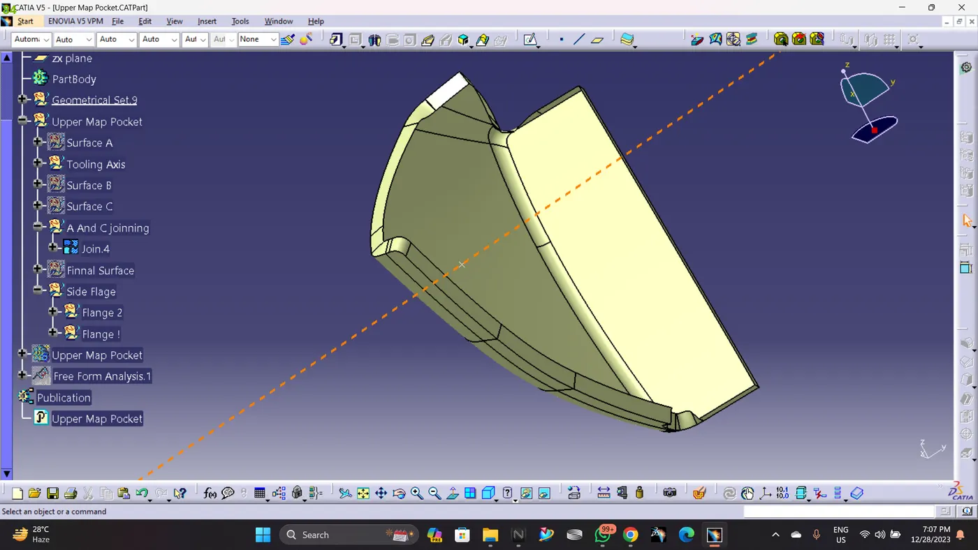
Class A,B And C Joining :
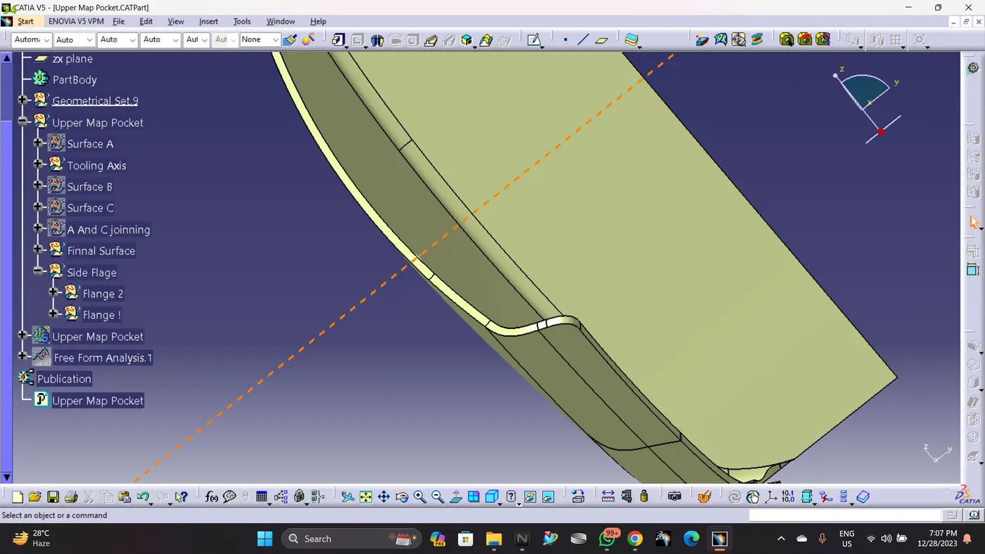
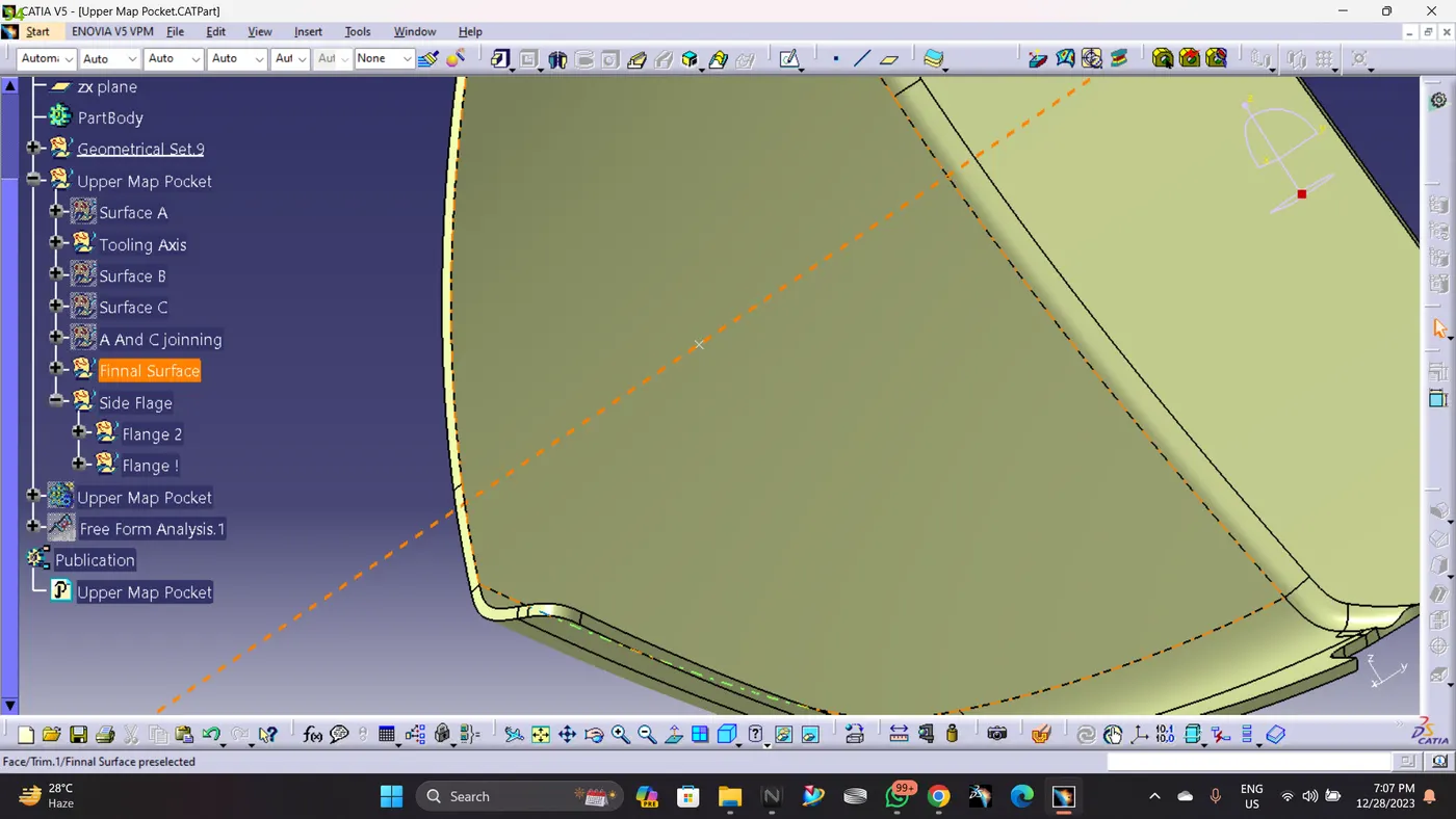
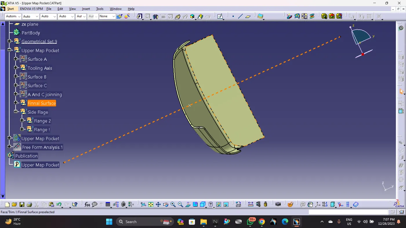
Closed Body :
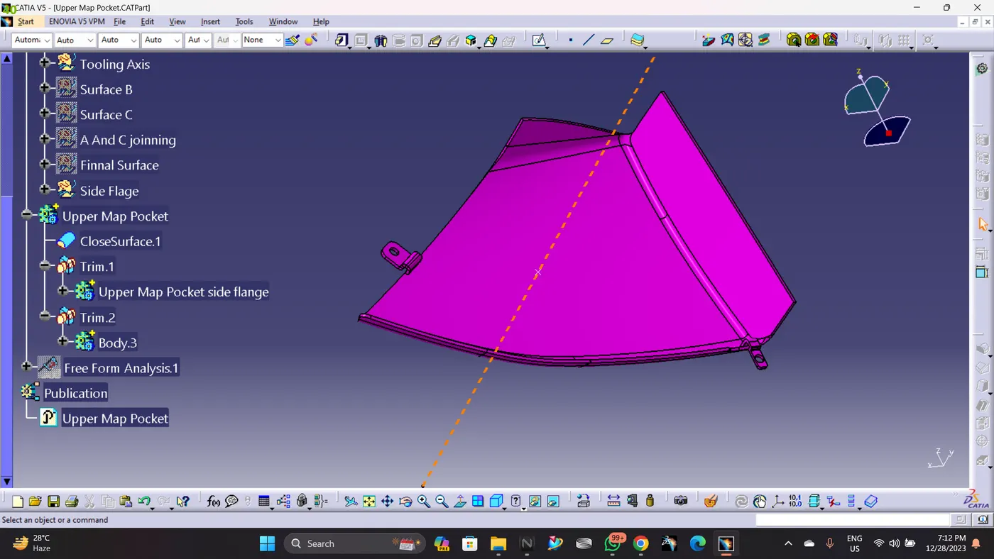
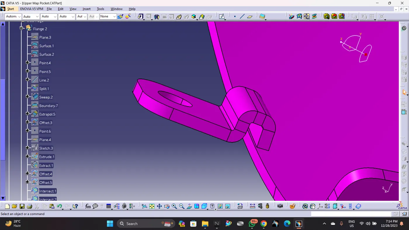
Creating flage on Upper Map Pocket :
Creat 2 Flange on main body
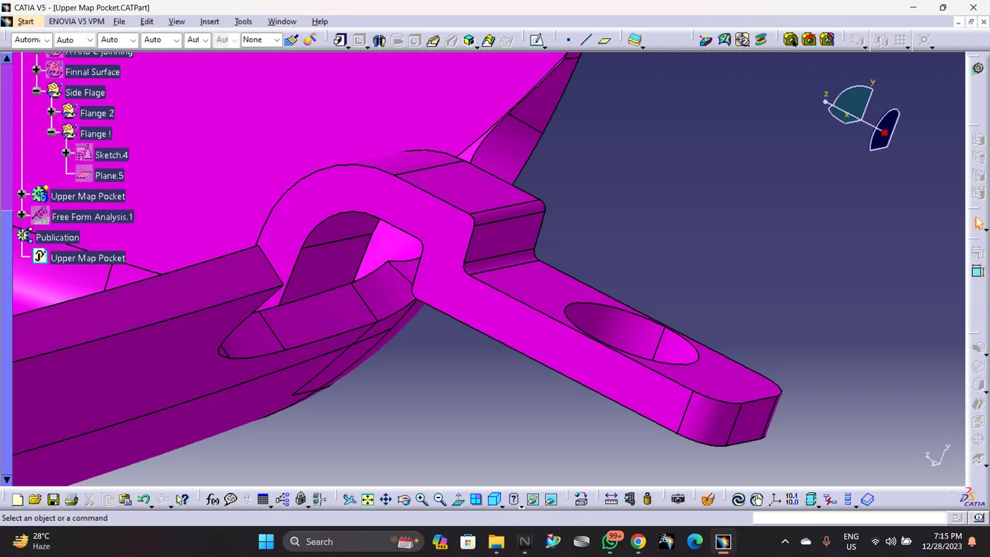
In oder to Join the Map Pocket with the other bodies, I created 2 Flanges seperatly with counter holes, Flanges are different based on the engineering features will be held. Then these flanges are assembled to the main body (Upper Map Pocket) by unitrim feature.
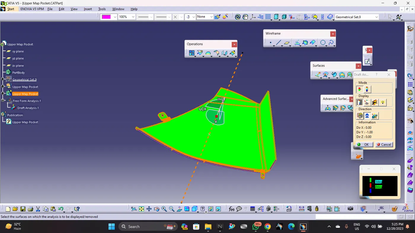
Drafting Analysis :
D) Lower Map Pocket:
Creat Class A:
Given Surface
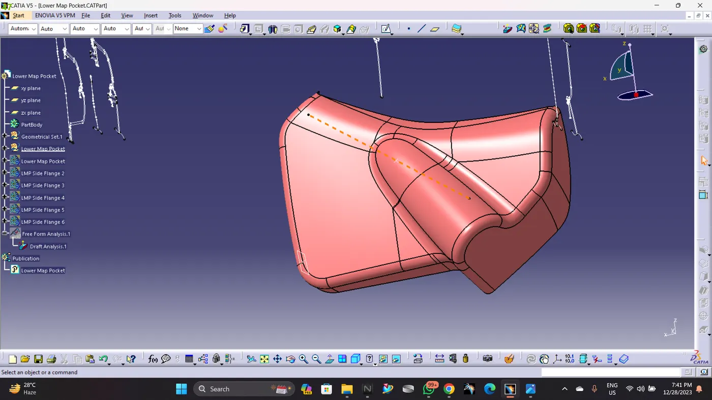
Class A Surface
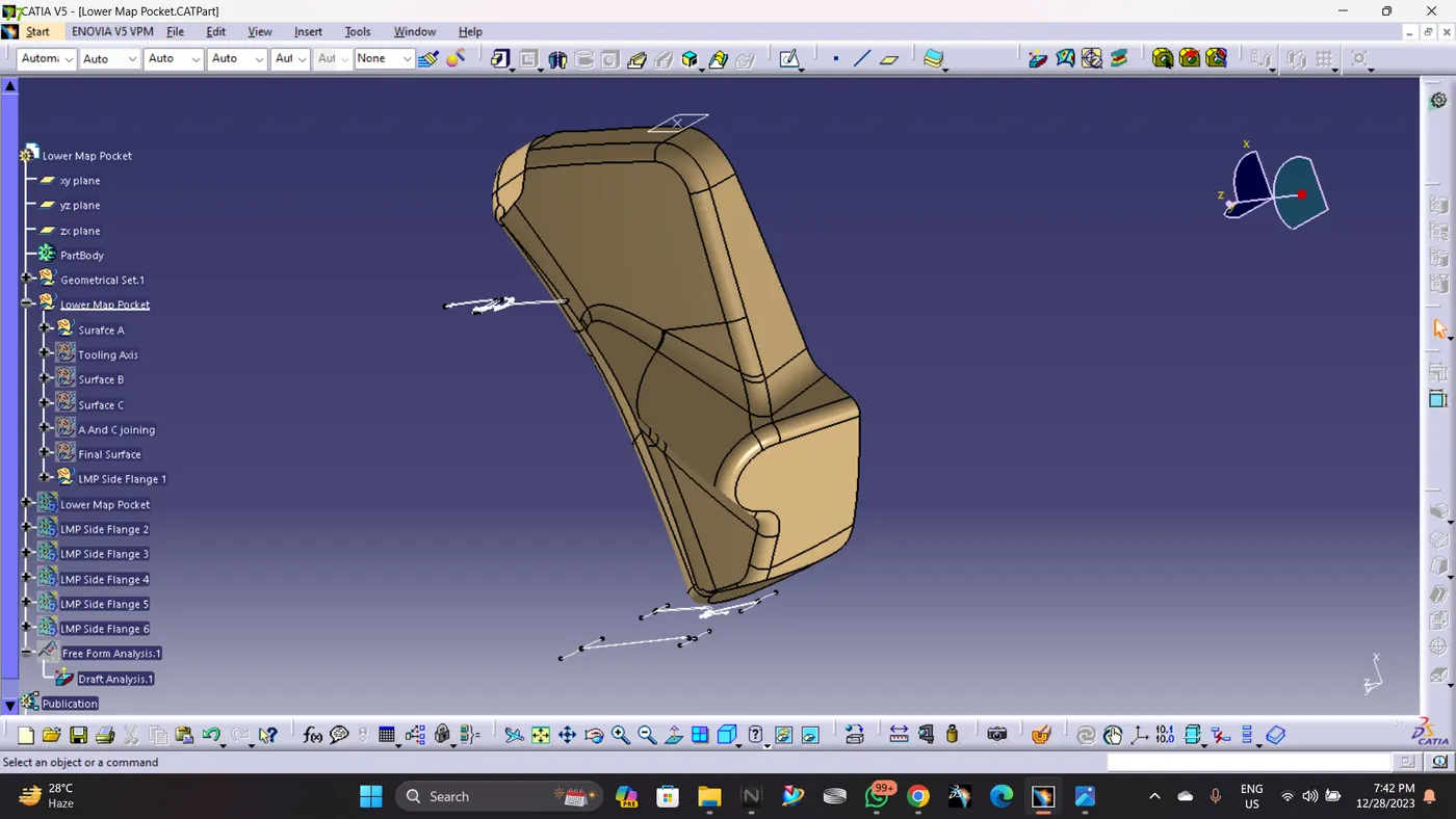
Tooling axis creation:
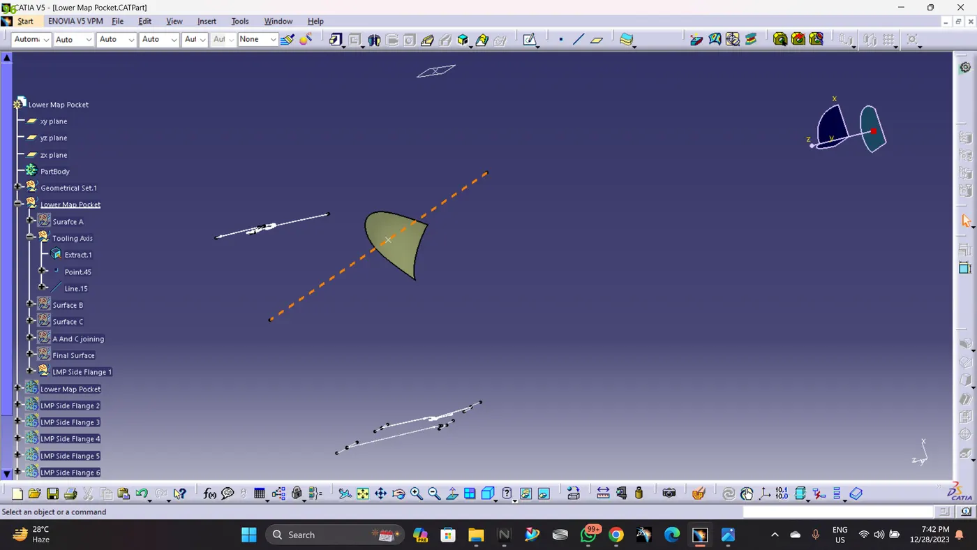
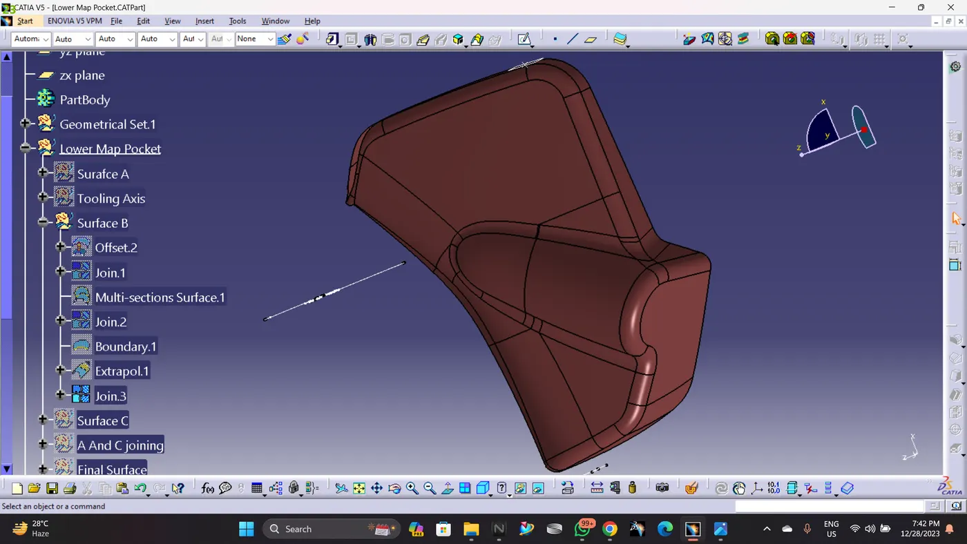
Creation of class B surface:
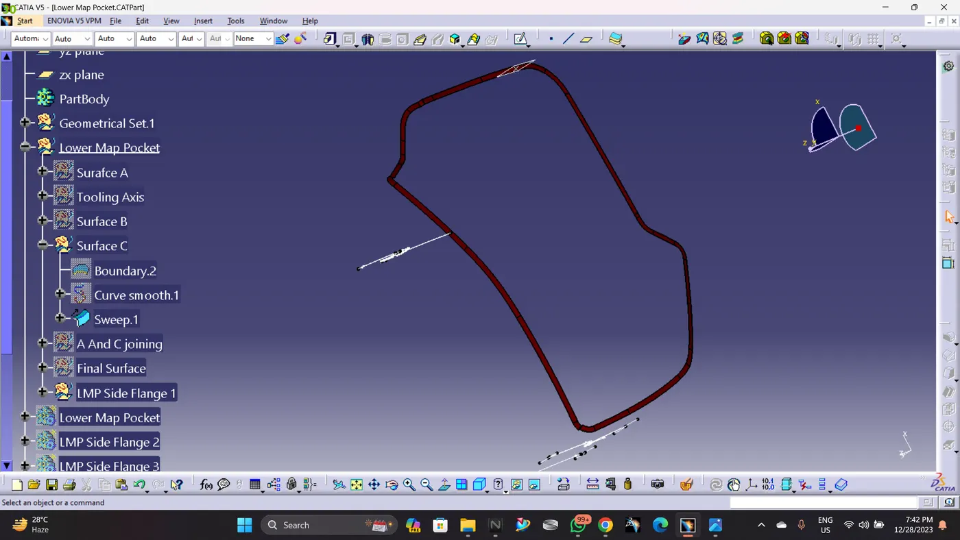
Class C is created by sweeping Improved Class A Surface and it has been trimed with Class B Surface.
Creation of class C surface :
Class A and Class C Joining:
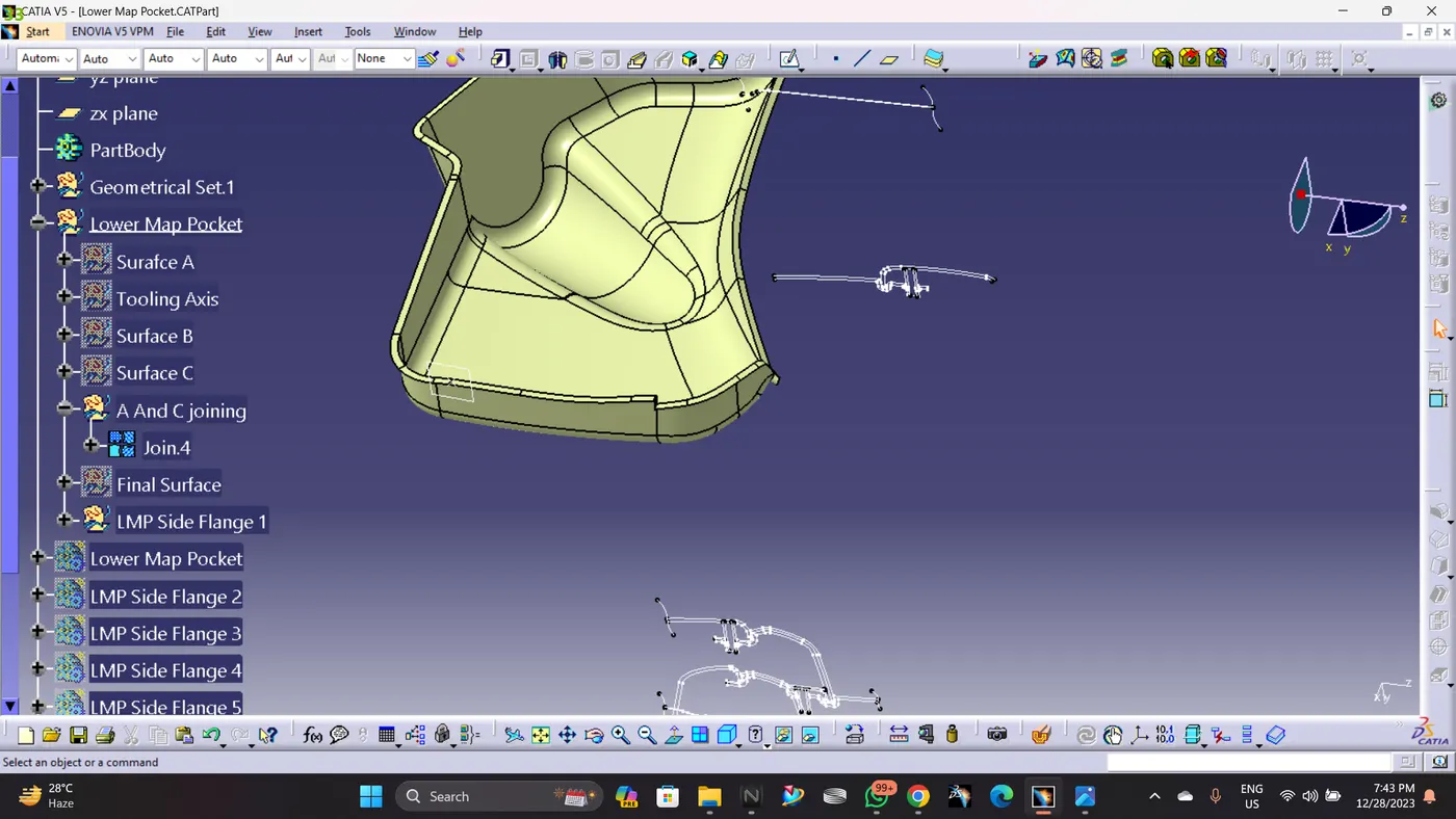
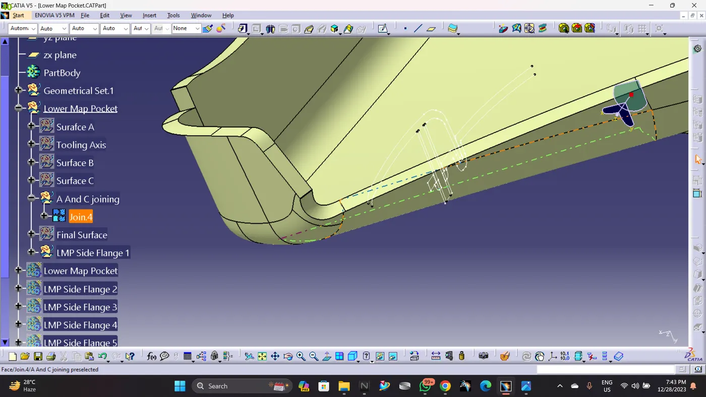
Class A,B And C Joining:
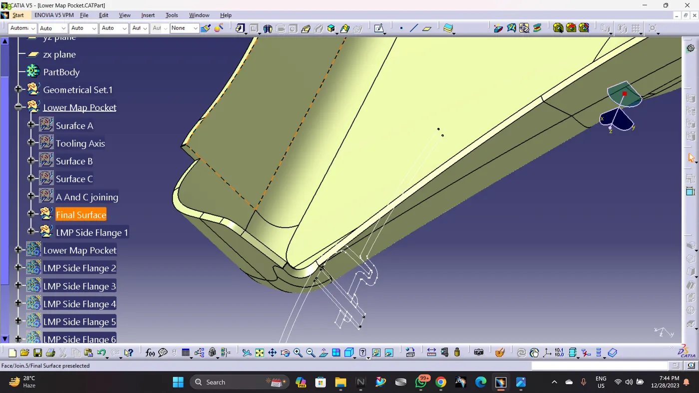
Closed Body:
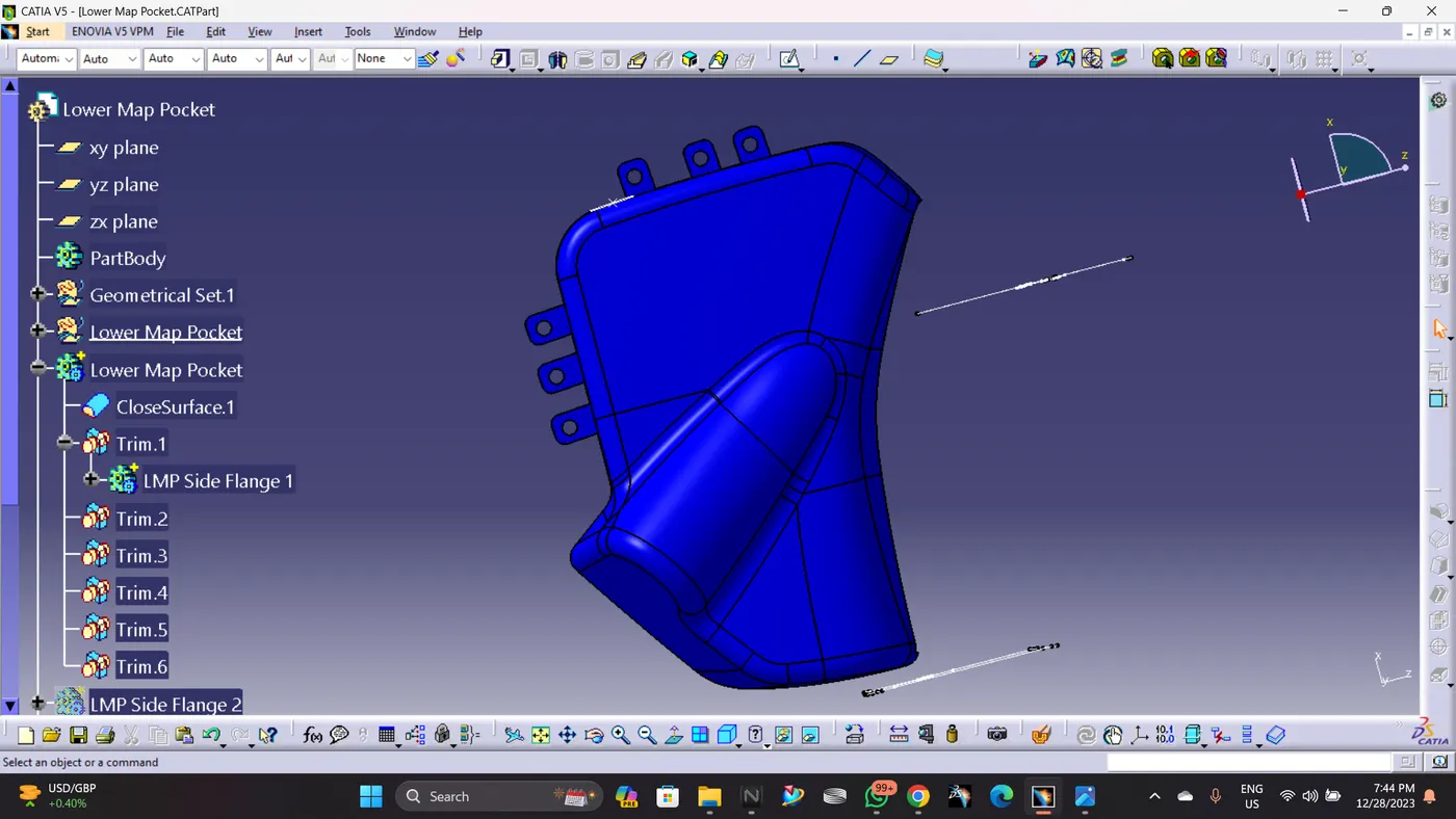
Creating flage on Lower Map Pocket:
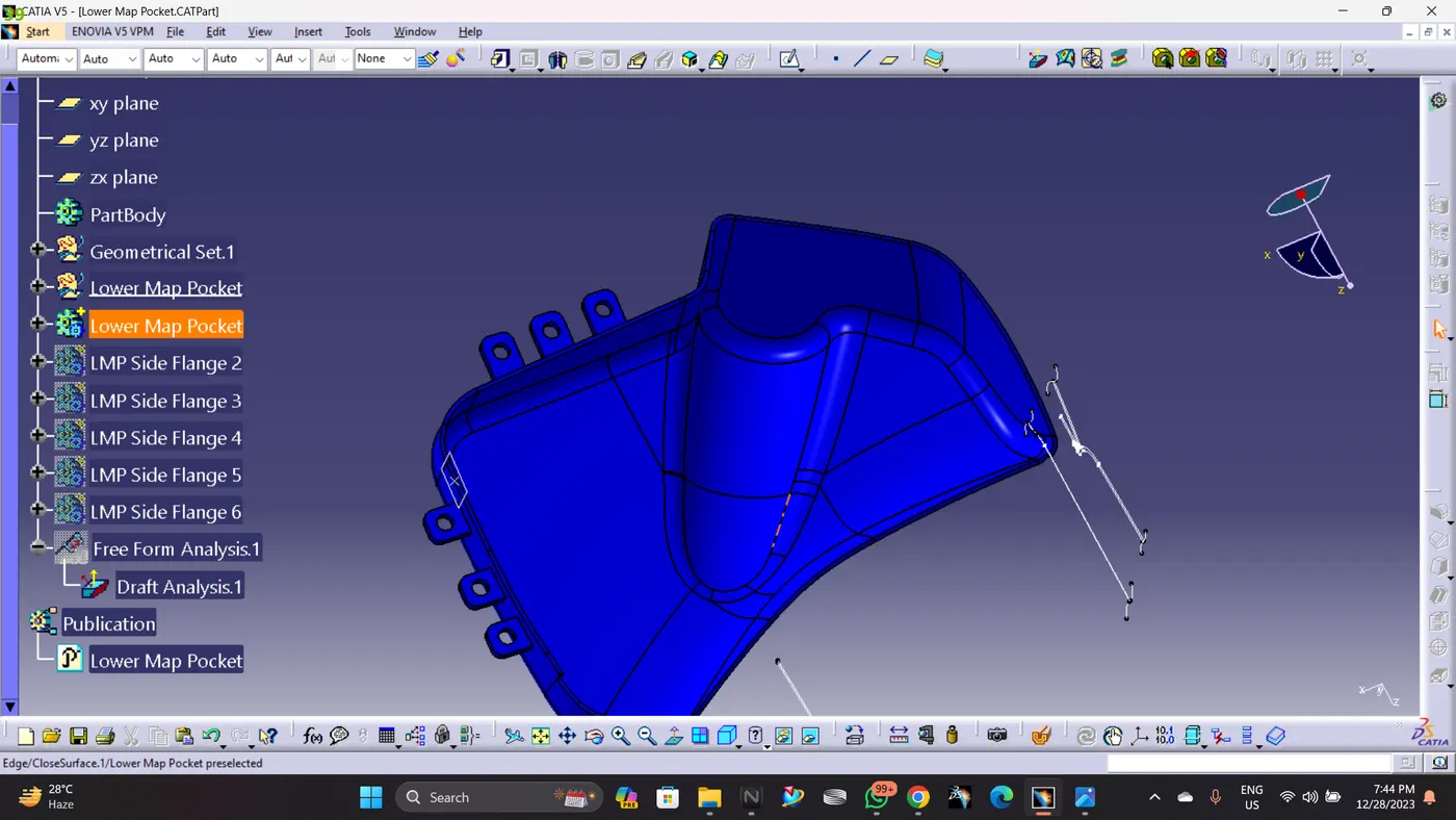
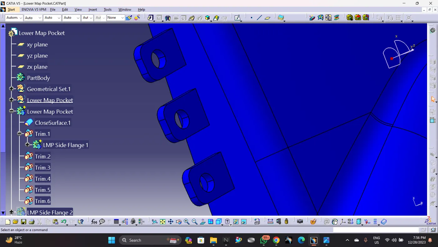
In oder to Join the Bottle Holder with the other bodies, I created 6 Flanges with counter holes, Flanges are different based on the engineering features will be held. Then these flanges are assembled to the main body (Bottl Holder) by unitrim feature.
Drafting Analysis:
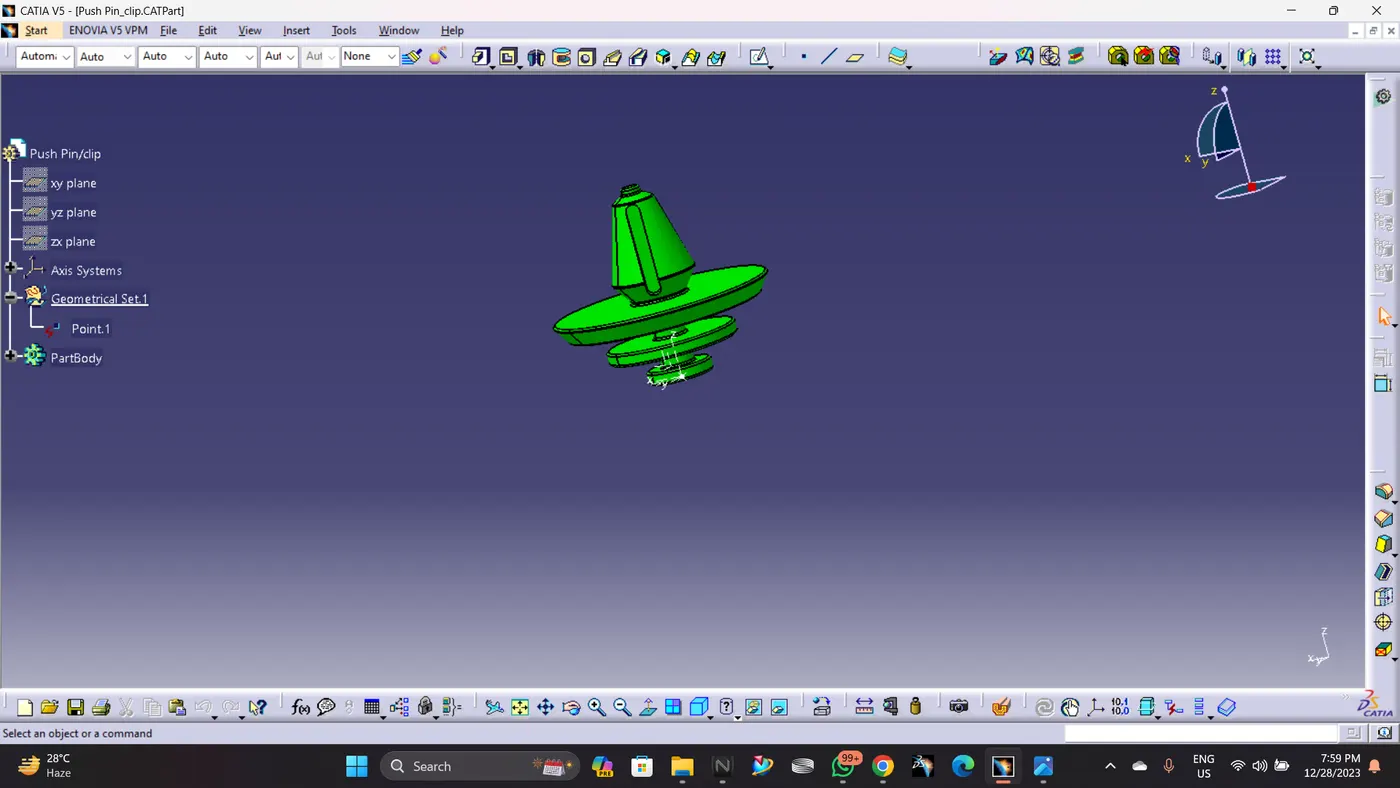
Push Pin:
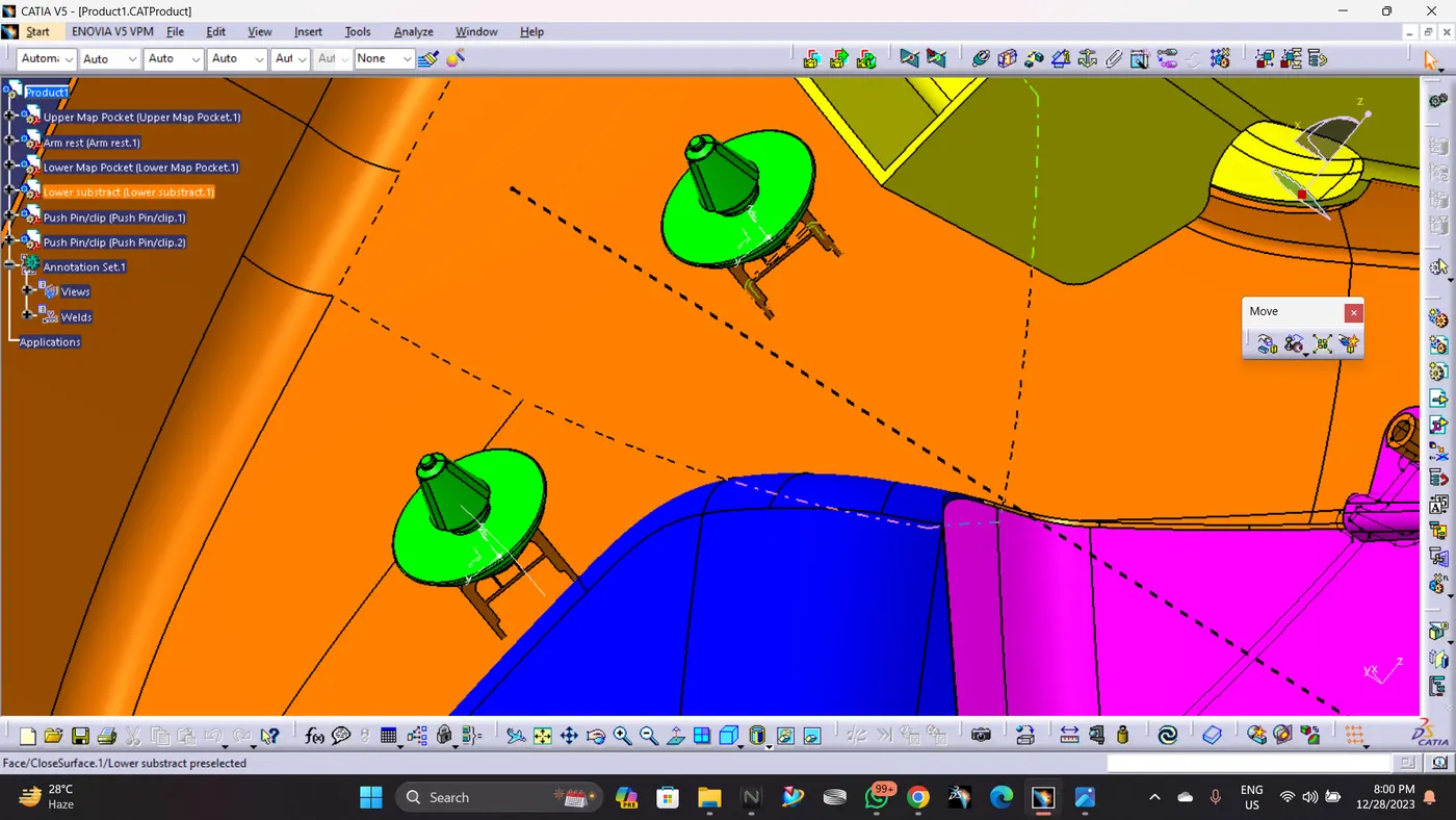
As I have created two Dog Houses for this part assembly, i need to inport two Push pins.
Both are assembled correctly as shown:
Product:
Door Trim panel: Final Porduct