Week 12- Final project
AIM
To design and development of vehicle interior door trim using catia v5 with given class A surface along with master section. Also create the side attachment features as per design rules.
OBJECTIVE:
- To create thickened part using master section for reference
- To create the mounting features as per design guidelines in the industry and with master sections
- To perform draft analysis & tooling analysis
INTRODUCTION:
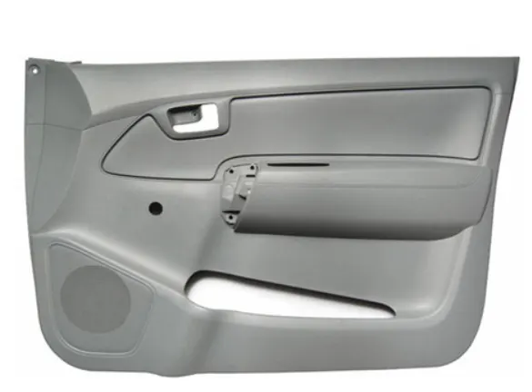
The door panel is the interface between the interior of the car and the inner workings of the door. Generally the door panel is divided into parts for easy designing like arm rest, map pocket, lower substrate. These require one of the toughest requirement among the interior parts of the car. this should be designed to with stand the load while being less than 2mm in thickness and also to protect the occupants collisions.
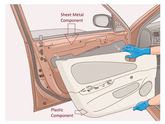
METHODOLOGY:
1. creating the toolong axis
The tooling direction is used to find the direction in which the part is removed from the core and cavity. the draft angle should be positive to the tooling axis to manufacture the component easily. The step by step procedure of creating the tooling axis is given below.
Step 1:
Creating the tooling axis for map pocket by create a point on surfaces a point on surfaces respectively to the 0 value. it automatically create at mid surface and generate the line to the direction of y axis.
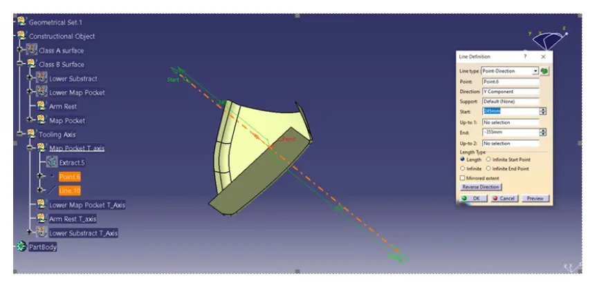
Step 2
Creating the tooling axis for lower map pocket by create a point on surfaces respectively to the 0 value. it automatically create at mid surface and generate the line to the direction of y axis.
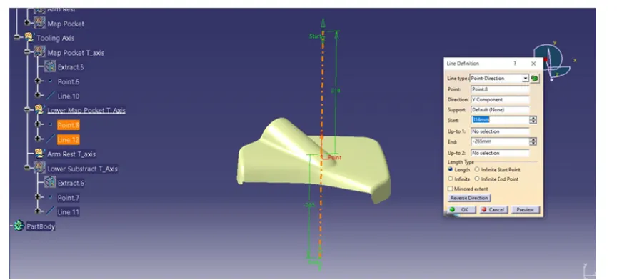
Step 3
Creating the tooling axis for lower substrate by create a point on surfaces respectively to the 0 value. it automatically create at mid surface and generate the line to the direction of y axis.
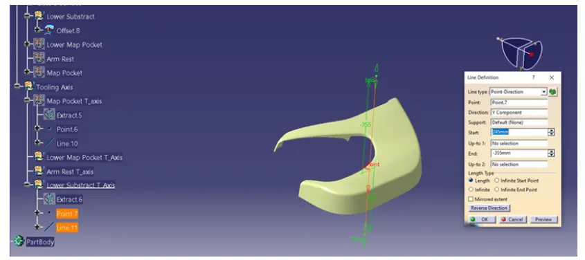
Step 4
Creating the tooling axis for arm rest by create a point on surfaces respectively with axis system. Now create the intersection for z-y AND z-x axis respectively based on the point.
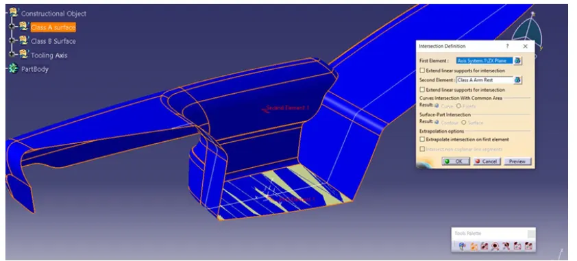
step 5
Creating the sliding tooling axis for the arm rest by extracting the side walls of the surface. creating the point on the surface with axis system. here y axis is considered as removal direction, hence line is created to the y axis as shown below.
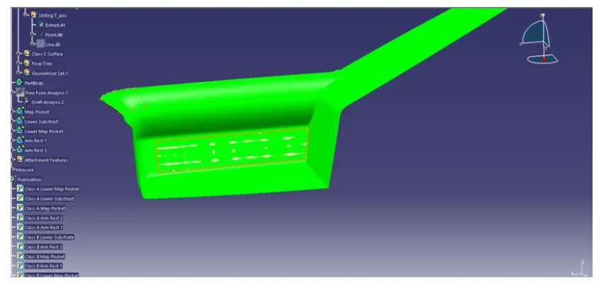
Creating the B surface
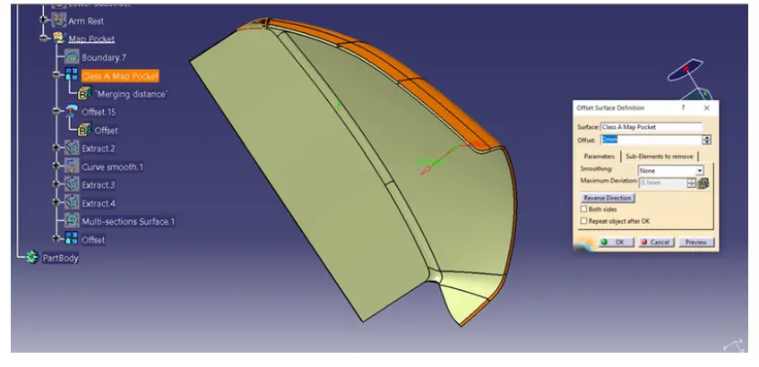
Creating the B-SURFACE by extracting the class A surface by each surfaces separately. it is offset to certain distance, making point on the master section to get the intersection as shown below.
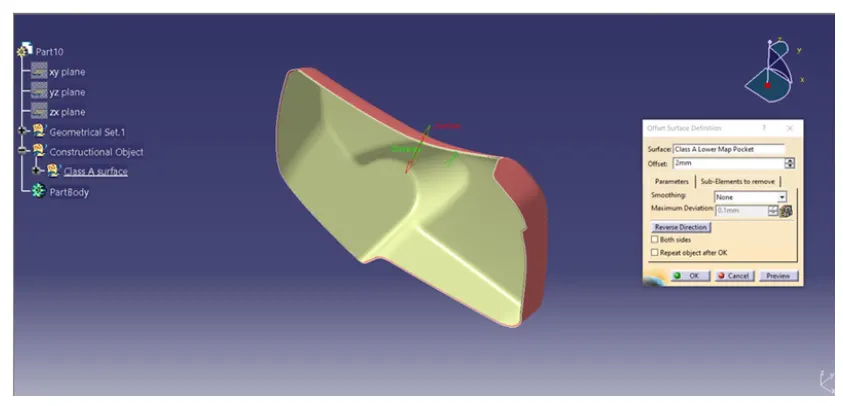
Creating of c surfaces
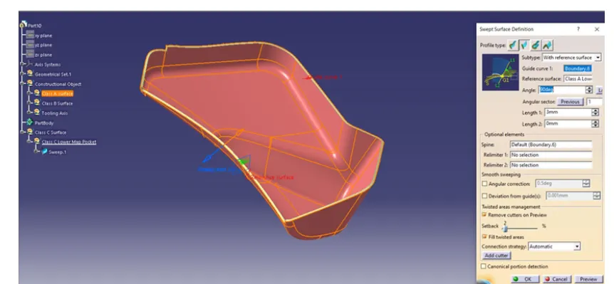
Extracting the boundary of class A surface and it is make into smooth curves to sweep the curves by using support surface to the 90 degree respectively.
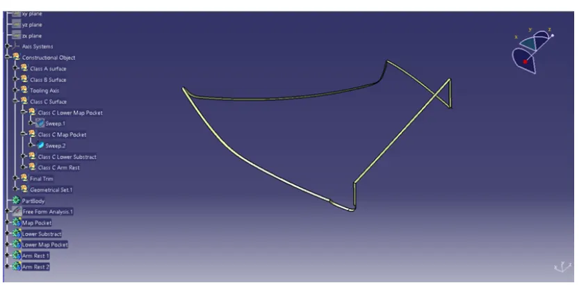
Once the all surface joined together it extrapolated to certain distance to trim with A class surface to C surface. Finally we created class C surface.
Making the Final palstic component:
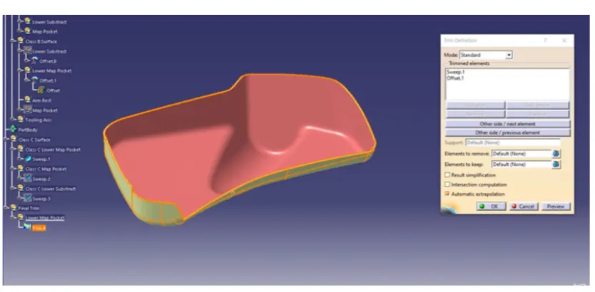
To make the final component the class c surface is trimmed with class B surface. the ouput will get the component with 2mm thickness of surface and it is converted into solid body using insert body option in part design as shown below.
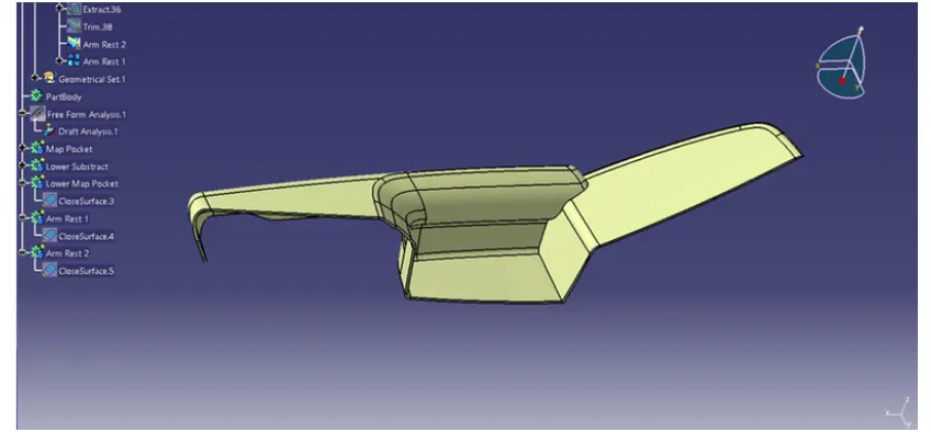
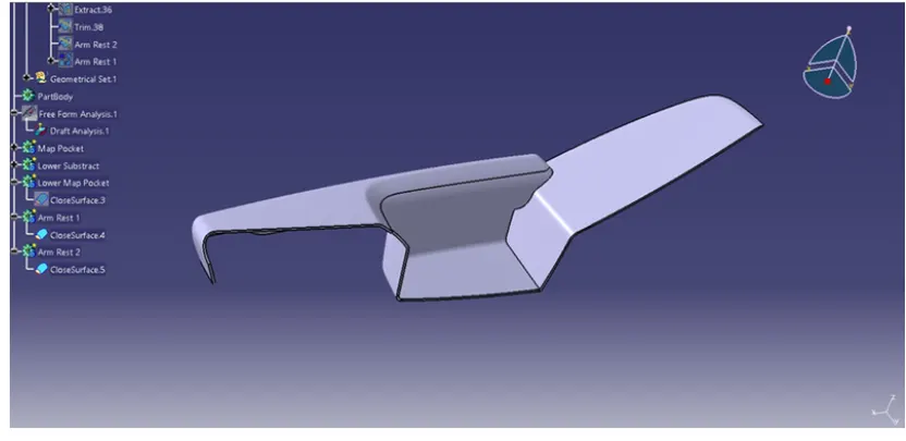
Creation of Attachment feature to the Door Trim:
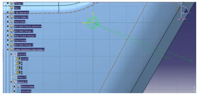
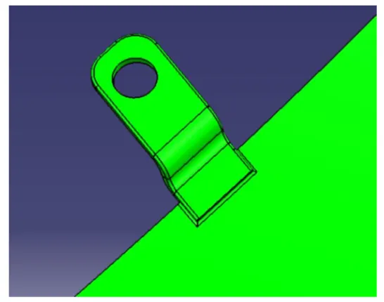
Creating the sketch by extracting the class A surface by each surfaces separately point and axis system created simultaneously on the surface. using positioned sketch making as shown below.
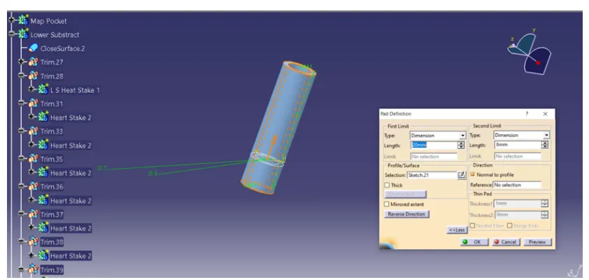
Step 2
The sketch feature is then extracted to the required dimension. and it is drafted for the 0.5 deg to the sliding tooling axis. it is filleted for radius 0.25 of smooth edges as shown below.
Creating the Push Pin clip:
step 1
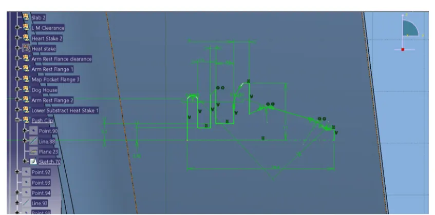
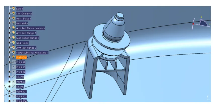
The push pin clip has been sketched for the required dimension. it is revolved to make solid component as shoen below
Draft analysis on door Trim solid body with attachment features:
step 1
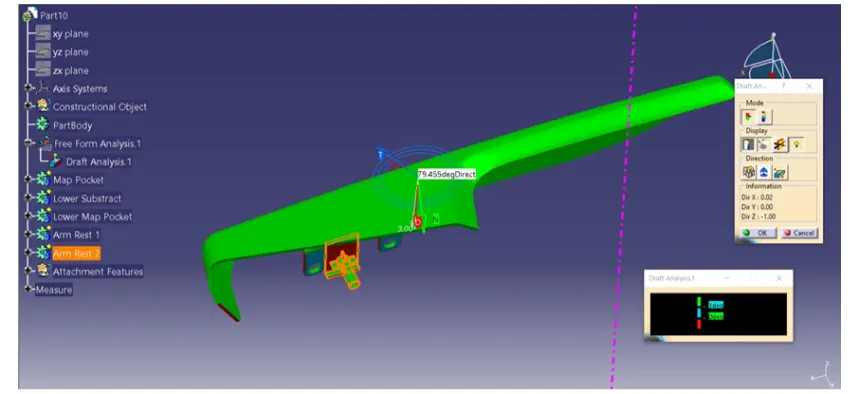
Frist we have to set the compass on the main tooling axis to get the direction of core and part moves along as shown below.
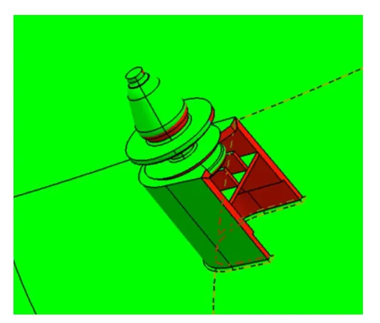
Here the draft angle is given as 3 degree. hence we achieved green colour on top surface. hence it accepts the draft angle for the surface. so we build good quality component.
we can check the angle of draft given to surface by using draft tool analysis just point the over the surface where we have check angle of given draft o the component.
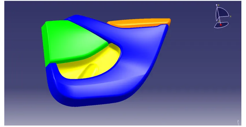
screenshot view of Door Component:
Front view:
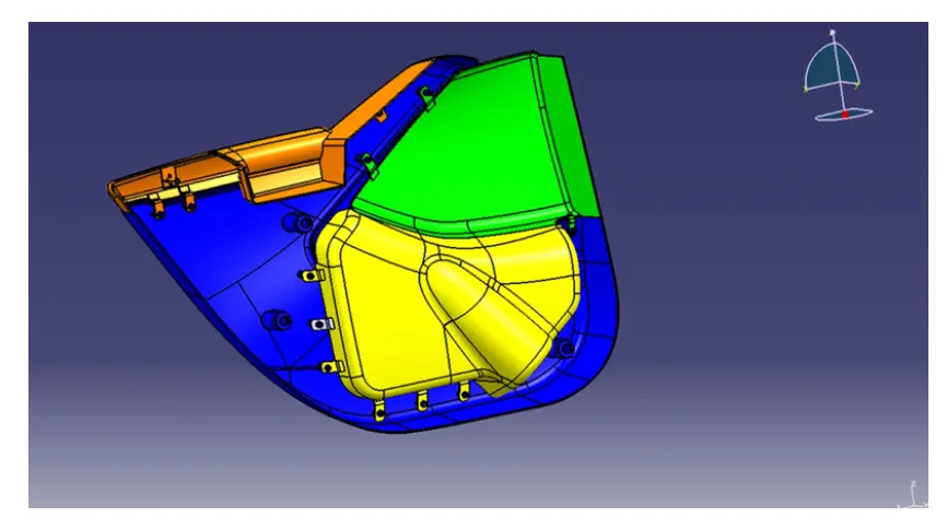
Back view along with attachment features:
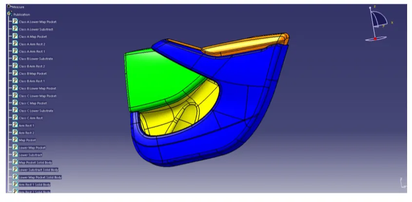
Publication
CONCLUSION
Creation of the car interior door trim is designed using the given class A surface as the input and class B and C surface created with the help of class A surface. By using the given master section attachment features i.e. Heat stakes,flanges,Dog house and push clips are created using the design rules. The draft analysis has been performed to analysis the draft of the component features. the analysis will verify that all surfaces are favorable for being pulled from a cavity.it may also highlight or given insight to defect areas.