Week 12- Final project
FINAL PROJECT
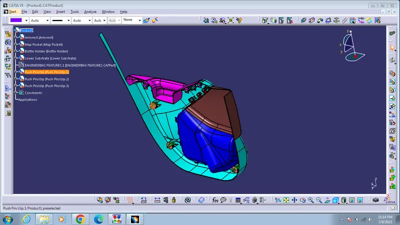
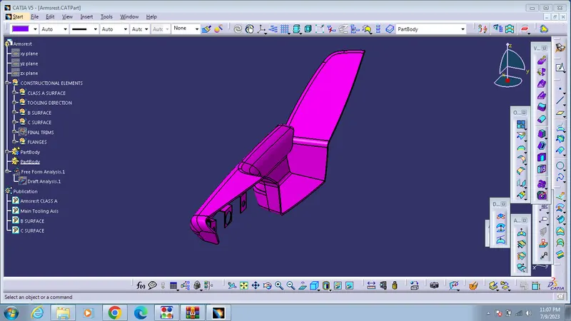
As per the given cad file, import the file to assembly design and devided into 4 parts part named armrest.Firstly I have made class A surface to a geometrical set named Class A and made the surface to Publication.
Then added new geometrical set named Tooling axis and start to create the tooling axis. For that I visualised the direction which our tooling axis may take in the X, Y AND Z components and found that it is appropriate in the Y direction and drawn the line through that direction. Then made checked the draft analysis and made it as my tooling axis and added to Publication.
Then I added a new geometrical set named B surface and started to work on my need B surface. For that , I just offsetted my class A surface to 2.5 mm inwards. Then I used multisectionsurface tool to clear the patching areas in the offsetted surface. Thus I got my B surface and i added it to Publication. Then I extrapolated my B surface a little for the easy trimming later.
Then I created new geometrical set named C surface and started to work on the C surface. For the creation of the C surface, I have taken the boundary of the Class A and sweeped it to 90 degress downward with reference to class A surface to about 3 mm. Thus I got my required C surface too.
Then I created new geometrical set named Final trim and done the trimming together with Class A and C surface.
Then later the trimmed portion with B surface. Thus I got my required design of the part which was hollow inside. men i added a new part body and closed the hollow part using the part design feature tool Close surface).
Then created 6 flanges using positioned sketch and sketched properly 6 falanges and extrude that the given equation and trimed , drafted using equation.
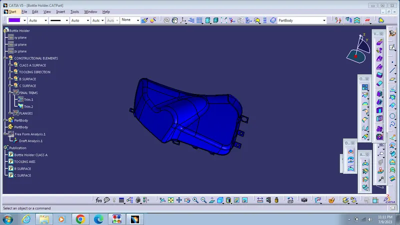
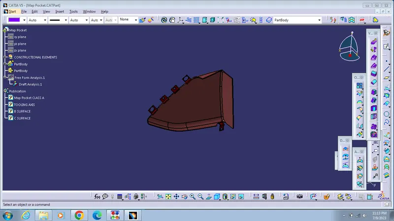
And other parts named bottle holder,lower substrate map pocket and all are done the same way of armsrest.
I have made class A surface to a geometrical set named Class A and made the surface to Publication.
Then added new geometrical set named Tooling axis and start to create the tooling axis. For that I visualised the direction which our tooling axis may take in the X, Y AND Z components and found that it is appropriate in the Y direction and drawn the line through that direction. Then made checked the draft analysis and made it as my tooling axis and added to Publication.
Then I added a new geometrical set named B surface and started to work on my need B surface. For that , I just offsetted my class A surface to 2.5 mm inwards. Then I used multisectionsurface tool to clear the patching areas in the offsetted surface. Thus I got my B surface and i added it to Publication. Then I extrapolated my B surface a little for the easy trimming later.
Then I created new geometrical set named C surface and started to work on the C surface. For the creation of the C surface, I have taken the boundary of the Class A and sweeped it to 90 degress downward with reference to class A surface to about 3 mm. Thus I got my required C surface too.
Then I created new geometrical set named Final trim and done the trimming together with Class A and C surface.
Then later the trimmed portion with B surface. Thus I got my required design of the part which was hollow inside. men i added a new part body and closed the hollow part using the part design feature tool Close surface).
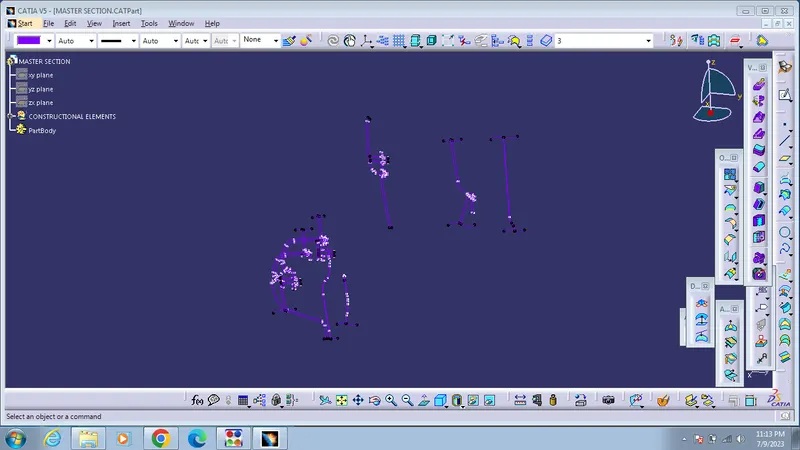
And all are joined using assembly design with proper method and i created amaster section
And finally i saved as partfiles and product files
THANK YOU